USER AND INSTALLATION MANUAL - KACO new energy, Inc.
USER AND INSTALLATION MANUAL - KACO new energy, Inc.
USER AND INSTALLATION MANUAL - KACO new energy, Inc.

Create successful ePaper yourself
Turn your PDF publications into a flip-book with our unique Google optimized e-Paper software.
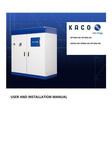
XP100U-H2/ XP100U-H4<br />
XP83U-H6/ XP90U-H6/ XP100U-H6<br />
<strong>USER</strong> <strong>AND</strong> <strong>INSTALLATION</strong> <strong>MANUAL</strong>
IMPORTANT SAFETY INSTRUCTIONS<br />
SAVE THESE INSTRUCTIONS<br />
This manual contains important instructions for the Inverter 1 that shall be followed during installation, operation,<br />
and maintenance of the inverter.<br />
Warning - These service instructions are for use by qualified personnel only. To reduce the risk of electric shock,<br />
do not perform work other than that specified in the operating instructions unless you are qualified to do so.<br />
Caution - To reduce the risk of fire, connect only to a circuit provided with 150 (H4 models), 400 (H2 models)<br />
and, 125 (H6 models) amperes maximum branch-circuit over current protection in accordance with the National<br />
Electrical Code, ANSI/NFPA 70.<br />
Warnings<br />
A warning describes a hazard to equipment or personnel. It calls attention to a procedure or practice, which, if<br />
not correctly performed, could result in damage to or destruction of part or all of the Inverter equipment and/or<br />
other equipment connected to the Inverter equipment or personal injury.<br />
DANGER!<br />
“DANGER” indicates a hazardous situation which, if not avoided, will result in death or serious injury.<br />
WARNING!<br />
"WARNING" indicates a hazardous situation which, if not avoided, could result in death or serious injury.<br />
1<br />
Hereinafter referred to as all five Models (XP100U-‐H2, XP100U-‐H4, XP100U-‐H6, XP83U-‐H6, and XP90U-‐H6), unless specific model names <br />
are indicated. <br />
Page 2
CAUTION!<br />
"CAUTION" indicates a hazardous situation which, if not avoided, could result in minor or moderate injury.<br />
BURN HAZARD!<br />
Do not touch. The Inverter contains components that become hot during normal operation.<br />
Other Symbols<br />
INFORMATION!<br />
This symbol accompanies notes that you should know and use to ensure optimal operation of the system.<br />
Wiring Requirements<br />
All wiring methods and materials shall be in accordance with the National Electrical Code ANSI/NFPA 70, as well<br />
as all state and local code requirements. Cable sizes in the chart below are the minimum. Because the field<br />
connections are bus bars for accepting crimp lugs, larger cables can be used if needed.<br />
Grid Connection<br />
XP100U-H4/ XP83U-H6/ HP90U-H6/ XP100U-H6<br />
Number of GRID cables Cable Size Torque<br />
A, B, C, N 4 1AWG<br />
All 194 (90℃) copper wire, 40 lbs-ft<br />
tightening torque<br />
PE 1 4AWG<br />
194 (90℃) copper wire, 40 lbs-ft<br />
tightening torque<br />
Page 3
XP100U-H2<br />
Number of GRID cables Cable Size Torque<br />
A, B, C, N 4 300kcmil<br />
All 194℉ (90℃) copper wire, 40 lbs-ft<br />
tightening torque<br />
PE 1 4AWG<br />
194℉ (90℃) copper wire, 40 lbs-ft<br />
tightening torque<br />
PV Connection<br />
XP100U-H2/ XP100U-H4/ XP83U-H6/ XP90U-H6/ XP100U-H6<br />
Number of PV strings Cable Size Torque<br />
1 600kcmil<br />
All 194℉ (90℃) copper wire, 40 lbs-ft<br />
tightening torque<br />
Hot,<br />
Return<br />
2 300kcmil<br />
All 194℉ (90℃) copper wire, 40 lbs-ft<br />
tightening torque<br />
4 1/0AWG<br />
All 194℉ (90℃) copper wire, 40 lbs-ft<br />
tightening torque<br />
PE 1 2AWG<br />
194℉ (90℃) copper wire, 40 lbs-ft<br />
tightening torque<br />
Page 4
CONTENTS<br />
IMPORTANT SAFETY INSTRUCTIONS .................................................................................................... 2<br />
1. About This Manual ................................................................................................................ 6<br />
2. Safety .................................................................................................................................... 7<br />
3. The blueplanet Inverter Overview ........................................................................................ 13<br />
4. Unpacking ........................................................................................................................... 17<br />
5. Installation & Transportation ................................................................................................ 18<br />
6. Connecting the Conduit ...................................................................................................... 23<br />
7. Electrical Connection ........................................................................................................... 26<br />
8. Connecting User Interfaces .................................................................................................. 34<br />
9. Commissioning ................................................................................................................... 45<br />
10. Opening the Inverter ........................................................................................................... 47<br />
11. Operating ............................................................................................................................ 49<br />
12. Parameters .......................................................................................................................... 54<br />
13. Faults & Warnings ............................................................................................................... 57<br />
14. Maintenance ....................................................................................................................... 61<br />
15. Error Codes ......................................................................................................................... 66<br />
16. Specifications ...................................................................................................................... 70<br />
17. Configuration ...................................................................................................................... 75<br />
18. Certifications ....................................................................................................................... 76
1. ABOUT THIS <strong>MANUAL</strong><br />
This manual provides information about the Inverter. This manual contains instructions to install, operate,<br />
maintain and troubleshoot the <strong>KACO</strong> Inverter. The user must keep this manual available at all times.<br />
This manual contains 5 sections and 3 appendixes.<br />
Safety is important. The Inverter operates with high voltages. Improper use or control of the inverter can cause<br />
an accident and damage to the inverter or the user. The user must understand directions thoroughly in each<br />
section in order to properly install, operate, and maintain the Inverter.<br />
1. The introduction describes the features of Inverter and details the components in the Inverter.<br />
2. The installation & operation section details how to install and operate the Inverter and how to use the Graphic<br />
User Interface (GUI).<br />
3. The fault & warning section contains a list of error codes of the Inverter and their descriptions.<br />
4. The maintenance section contains directions on how to clean and replace fans, and periodically check the<br />
parts of the Inverter.<br />
5. The parameters section contains parameter settings for the Inverter.<br />
A. The specification section details the Inverter specifications.<br />
B. The user Interface section will provide information about the digital interface, analog interface, Ethernet and<br />
RS485 serial connection of the Inverter.<br />
C. The configuration section shows the configuration of the Inverter.<br />
Contact Information<br />
<strong>KACO</strong> <strong>new</strong> <strong>energy</strong> <strong>Inc</strong>.<br />
USA<br />
Tel: +1 (415) 931-2046<br />
Fax: +1 (415) 931-1688<br />
E-mail: kacoinfo@kaco-<strong>new</strong><strong>energy</strong>.com<br />
Page 6
2. SAFETY<br />
Appropriate Usage<br />
Any other application of the Inverter or installation of components and modifications which are not explicitly<br />
allowed endanger the safety and void the warranty as well as the operation permit.<br />
A: PV Modules<br />
B: String Combiner Box<br />
C: Inverter<br />
D: AC overcurrent protection<br />
E: Grid<br />
Basic Solar Power System with the Inverter<br />
Page 7
Safety Instructions<br />
DANGER!<br />
High voltages are present in the live components of the low voltage grid.<br />
Death may result from burns and electric shock.<br />
Do not touch the live components of the Inverter or low-voltage grid.<br />
Pay close attention to all safety precaution measures regarding the low voltage grid.<br />
Page 8
DANGER!<br />
During operation, high voltages are present in the Inverter.<br />
Death may result from burns and electric shock.<br />
Before commencing work on the Inverter disconnect completely and ensure that the device will not be<br />
accidentally energized.<br />
Ensure that no voltage is present.<br />
Ground and short-circuit.<br />
Cover any nearby live parts.<br />
DANGER!<br />
Normally grounded conductors may be ungrounded and energized when a ground-fault is indicated.<br />
Risk of electric shock.<br />
Test before touching.<br />
Contact customer support for information at <strong>KACO</strong> <strong>new</strong> <strong>energy</strong>, <strong>Inc</strong>. +1 (415) 931-2046.<br />
WARNING!<br />
Failure to follow the manual, the operating instructions and the safety precautions may lead to severe injury<br />
from electrocution.<br />
All work on the Inverter may only be done as described in this manual and must be performed by qualified<br />
personnel.<br />
Pay attention to all safety instructions.<br />
Follow all operating instructions.<br />
If problems occur when performing the work described here, contact the customer support department at<br />
<strong>KACO</strong> <strong>new</strong> <strong>energy</strong> <strong>Inc</strong>. +1 (415) 931-2046.<br />
Page 9
WARNING!<br />
Operating the Inverter if it’s damaged may cause severe injury from electrocution.<br />
The Inverter may only be used when it is functioning correctly.<br />
Regularly check the XP Inverter for visible damage and operate only if there is no visible damage.<br />
Ensure that all safety features are accessible at any time and that their correct operation is tested regularly.<br />
ATTENTION!<br />
The printed circuit board (PCB) components in the Inverter can be damaged by electrostatic discharge!<br />
When working on the Inverter and when handling the PCB components observe all ESD safety<br />
regulations. Discharge electrostatic charge by touching the grounded Inverter enclosure. Only then<br />
is it safe to touch any electronic components.<br />
Technical rules<br />
The installation must be in compliance with the local regulations and technical rules, in particular with regard to<br />
electrical connections. (National Electric Code NEC)<br />
The installer is responsible for knowing and understanding local standards and regulations as well as utility<br />
interconnection requirements.<br />
Page 10
Regulations concerning the prevention of accidents<br />
During the operation of the inverter, certain parts of the device carry high voltages, which may lead to severe<br />
personal injury or even death. The following precautions should be followed to minimize the risk of lethal<br />
hazards or personal injuries.<br />
The installation of the device must be in compliance with the relevant safety regulations or other applicable<br />
national or local provisions. Proper ground, conductor dimensioning and an appropriate short-circuit protection<br />
must be provided to ensure operational safety.<br />
All instrument covers must remain closed during operation.<br />
Prior to performing some visual checks and maintenance work the inverter must be disconnected from all power<br />
sources and protected against inadvertent activation. If measurements have to be conducted while the inverter is<br />
connected to power, NEVER touch live terminals. Remove all jewelry from your wrists and fingers. Ensure that<br />
the test equipment is in a proper and safe operating condition.<br />
When working on the inverter while energized, make sure to stand on an insulated surface and ensure that<br />
there is no connection to ground.<br />
Follow the instructions exactly as given in these operating and installation instructions and especially observe all<br />
information concerning possible hazards, warnings and precautions.<br />
This manual may not cover all possible scenarios. Should a specific problem occur that is not sufficiently<br />
explained, please contact your dealer or <strong>KACO</strong> <strong>new</strong> <strong>energy</strong>.<br />
Modifications/Changes<br />
CAUTION!<br />
Hazard of damage due to unauthorized modifications/manipulation! By no means manipulate the inverter or<br />
modify or change the inverter or any other parts of the installation<br />
Performing any modifications or changes on the inverter is generally prohibited. Performing any changes or<br />
modifications to the installation of the inverter is only permitted if in compliance with national standards and<br />
performed by qualified personnel.<br />
Page 11
Inverter shutdown<br />
WARNING!<br />
Hazardous live voltages can be present in the inverter even if the electrical connections are switched off or disco<br />
nnected. Please wait for 1 minute before accessing the inverter<br />
The inverter must be switched off for adjusting, maintenance and repair work. Please proceed as follows:<br />
1. Turn the inverter off by pushing the off button in the GUI.<br />
2. Turn the AC and DC switches to the OFF position<br />
a. (The off position is green and the on position is color coded red).<br />
3. Disconnect the inverter from the PV array.<br />
4. Disconnect the inverter from the grid.<br />
5. Check that the inverter is disconnected from all voltage sources.<br />
6. If possible Install lockout devices on the utility connection circuit breaker, AC and DC disconnect<br />
switches.<br />
7. Wait 1 minute for all capacitors inside inverter to discharge.<br />
8. When reactivating the XP inverter expect a five minute commission window.<br />
Page 12
3. THE BLUEPLANET INVERTER OVERVIEW<br />
Full digital control using digital signal processing (DSP)<br />
The <strong>KACO</strong> XP uses two DSPs to control the inverter and an ARM processor for user and external interface. These<br />
full digital control schemes offer enhanced reliability, accuracy, efficiency, flexibility and convenience.<br />
High reliability<br />
The <strong>KACO</strong> Inverter features built in reliability with redundant power supplies, highly efficient cooling of critical<br />
components and intelligent cooling fans. The fans are monitored and controlled according to load and<br />
environmental temperature conditions. All components used in the <strong>KACO</strong> XP are designed for industrial use. The<br />
IGBT stack was designed based on the IEEE WG PEBB TF2 standards. These standards mandate the use of<br />
laminated DC bus-bars that provide for very low stray inductance and gate drive interfacing with differential<br />
signaling. This feature enhances reliability and ease of maintenance. Full digital control technology of the XP<br />
also enhances reliability by reducing component count compared to traditional analog electronics.<br />
Powerful human interface and networking<br />
The Inverter’ features a powerful and friendly Graphic User Interface (GUI). The “all-in-one” design for the GUI<br />
provides for more convenient operation and monitoring. The GUI is a big, easy to use display with color TFT LCD<br />
(480 x 272 dots) and provides detailed operating information in different languages. RS232, RS485, and<br />
Ethernet interfaces for networking are standard in the Inverter.<br />
System flexibility<br />
The Inverter provides 4 analog inputs, an S0 input, 1 programmable dry contact output A type (Normally open)<br />
and B type (Normally closed), and 1 digital input. The analog inputs are preconfigured for the user and allow<br />
easy connection of temperature sensors and a reference cell. The S0 input is preconfigured for smart metering.<br />
.<br />
Page 13
Shape & Components<br />
External shape<br />
Front<br />
Page 14
Left, Right and Back<br />
Page 15
Location of the Safety Notices<br />
The figure to the right shows the location of the safety<br />
notice on the Inverter.<br />
A. Front door handle.<br />
B. PEBB cover<br />
Caution, risk of electric shock, hot surface<br />
Caution, risk of electric shock<br />
C. Switch panel cover<br />
Caution, risk of electric shock<br />
D. Fuse panel cover<br />
Caution, risk of electric shock<br />
E. Control system panel<br />
Caution, risk of electric shock<br />
Refer to the operating instructions<br />
F. Filter capacitor cover<br />
Caution, risk of electric shock<br />
The Inverter identification<br />
You can identify the Inverter using the type plate. The inverter type identification plate can be found inside on<br />
the doors of the cabinet.<br />
Firmware<br />
The Inverter’ firmware is shown on the display of the GUI. The Inverter’ operator manual describes how to obtain<br />
the firmware version.<br />
Page 16
4. UNPACKING<br />
This section describes unpacking and inspection of the inverter.<br />
Unpacking and inspection<br />
All <strong>KACO</strong> inverters are thoroughly inspected before packing. Although they are shipped in sturdy packaging,<br />
damage can still occur during shipping and delivery. It is important to carefully inspect the shipping container<br />
and contents prior to installation. When you detect any external damage before or after unpacking, report the<br />
damage immediately to your <strong>KACO</strong> dealer and the shipping company that delivered the unit. If it is necessary to<br />
return the Inverter, please use the original packing material.<br />
If you need assistance with damaged inverter, contact your dealer or <strong>KACO</strong> <strong>new</strong> <strong>energy</strong> <strong>Inc</strong>.<br />
Contents<br />
A: Inverter<br />
B: User and Installation Manual<br />
C: Test Report<br />
D: Keys for GUI cover and front door<br />
Storage<br />
ATTENTION!<br />
The inverter should be properly stored to ensure optimal performance.<br />
The inverter should be closed when stored to protect from dust and moisture.<br />
If the storage period is longer, the inverter should be kept in a dry place.<br />
Page 17
5. <strong>INSTALLATION</strong> & TRANSPORTATION<br />
Selecting an appropriate place of installation<br />
If possible the inverter should be installed in an area that is as dry as possible. This is to ensure maximum<br />
product longevity. Additionally, if the ambient temperature at the installation site is above or below the<br />
specifications designated by the manufacturer, the inverter should then be mounted indoors where the ambient<br />
temperature can be controlled within the specifications. Again, this is in order to ensure maximum product<br />
longevity.<br />
The following rules should be observed while choosing the site for the installation of your inverter:<br />
1. Ensure good access for assembly or service work.<br />
2. Please ensure free air circulation at the sides of the housing.<br />
3. The place of installation must ensure proper heat dissipation. If necessary, provide forced ventilation of the<br />
room to ensure that heat is dissipated adequately.<br />
4. Ensure that the supporting area has an adequate load-bearing capacity.<br />
Weights and Dimensions<br />
XP100U-‐H2: Weight: 1400Kg <br />
XP100U-‐H4: Weight: 1400Kg <br />
XP83/90/100U-‐H6: Weight: 1100kg <br />
The installation site must be easily accessible for installation or service work and should preferably not expose the<br />
inverter to direct sunlight or enclose the inverter in an unventilated space.<br />
Page 18
Minimum Workspace Requirements<br />
The minimum clearance space shown below should be maintained for ventilation and access.<br />
*<br />
* If you use a left side conduit plate, the minimum clearance is 4 inches on the left side for installation but actual<br />
clearance will be dictated by the requirements of conduit fitting installation and maintenance accessibility.<br />
Installation Site Requirements<br />
The foundation must guarantee a solid and safe surface to bear the weight of the inverter.<br />
Page 19
Preparation of the mounting surface<br />
Prepare the mounting surface structure appropriately based on the chosen site<br />
Secure the Inverter to the chosen site with the pre-installed L-brackets.<br />
Position of the mounting holes (bottom view)<br />
Page 20
Foundation L-bracket surface mount<br />
Mounting L-bracket to the inverter<br />
L-bracket for mounting<br />
Transport Instructions<br />
Please note the weight of the inverter and follow the instructions below.<br />
The mode of transportation must support the weight the inverter.<br />
During transport be certain to center the weight of the inverter as the center is closer to the left side.<br />
Do NOT tilt the inverter while transporting.<br />
The pictures below are examples for transportation.<br />
Page 21
Fork lift from front or rear <br />
Crane fork from front or rear <br />
Eye nuts with crane rack <br />
Slope angle = 0° in any direction <br />
Page 22
6. CONNECTING THE CONDUIT<br />
In this section, see how to insert the cables in the inverter and where to punch the holes for the conduit fittings.<br />
NOTICE!<br />
When installing, please be cautious that water is not able to enter into the inside of the cabinet.<br />
Only recognized NEC compliant watertight conduit and fittings must be used for outdoor<br />
applications. Moisture can affect the performance of the inverter through improper conduit or<br />
hubs.<br />
How to install the cables<br />
There are two ways of connecting cables shown in the following figures.<br />
The field wiring area is designed for DC cable, AC cable and data cables.<br />
The conduit entry points can be used for any cables. Example: Left side for DC conduit and bottom for AC<br />
conduit. <br />
Using the left side panel for cables<br />
1. Remove the bolts which secure the plate to the inverter.<br />
2. Remove the plate.<br />
3. Mark all the holes for the conduit. You need conduit for the AC, DC and data cables.<br />
4. Punch holes for the conduit.<br />
5. Attach the plate to the Inverter.<br />
6. Attach the bolts and tighten.<br />
7. Attach the conduit with the appropriate conduit fittings.<br />
a. Ensure that proper conduit duct sealant is used to prevent rodent and insect infestation.<br />
b. The bottom plate must be secured in place during operation. If conduit is used, the proper<br />
conduit fittings must be used.<br />
Page 23
Left panel dimensions for conduit<br />
Page 24
Using the bottom panel for conduit <br />
Bottom access panel for conduit<br />
Page 25
7. ELECTRICAL CONNECTION<br />
The electrical connections should only be made after the inverter has been installed in its final location. To<br />
complete the electrical connections, the AC and DC terminal connections must not be connected to any source<br />
of voltage. This will protect the installer from harm and ensure that the inverter is not accidentally activated.<br />
CAUTION!<br />
After the inverter has been installed in the fixed location, the electrical connection can be established<br />
Please be sure that both AC and DC side are disconnected from all voltage sources.<br />
Please be sure that the switches are locked out and switching-on unintentionally is not possible.<br />
NOTICE!<br />
The electronic printed circuit board components in the inverter can be damaged by static electricity.<br />
When handling the printed circuit boards, please follow ESD safety regulations.<br />
To prevent the damage from static electricity, touch the enclosure of the grounded inverter.<br />
Please go to the next step when you are sure it is safe.<br />
Page 26
Connection Area<br />
D<br />
D<br />
A: AC Connection<br />
B: DC Hot Connection<br />
C: DC Return Connection<br />
D: Ground Connection<br />
Page 27
PE Connection<br />
PE (Protective Earth) or Ground rails are located on both sides of the field wiring enclosure. Please ensure the<br />
Ground rails are connected with cables. Any of these connection points can be used for the Grounding<br />
Electrode Conductor (GEC).<br />
CAUTION!<br />
Before connection, please check that all external cabling is connected properly and not able to be energized<br />
accidentally.<br />
Page 28
Grid Connection<br />
The inverter is connected to the grid through AC bus bars which are located on the left bottom of the field<br />
wiring area of the inverter which are labeled A, B, C, and N. The minimum cable size is 1 AWG for both H4 and<br />
H6, and 300kcmil for the H2 model. The torque value for AC terminal connections is 40 lb-ft. The maximum AC<br />
overcurrent protection is 125A for the H6 model, 150A for the H4 model, and 400A for the H2 model.<br />
DANGER!<br />
Electric shock can result from handling the components with high-voltage present.<br />
Please be sure that all voltage sources are disconnected and cannot be accidentally energized.<br />
CAUTION!<br />
The inverter AC connections must have the proper phase rotation in order to connect to the grid and operate.<br />
Proper rotation is A-B-C. Please check with a phase rotation meter.<br />
If the phase rotation is incorrect an error will be displayed on the user interface and the inverter will not<br />
connect to the grid, if this happens reverse any two phases to correct the rotation.<br />
Page 29
IMPORTANT!<br />
Please check that the cables are connected and torqued properly.<br />
Use 90℃ copper conductors only.<br />
XP100U-H2 XP100U-H4 XP83U-H6 XP90U-H6 XP100U-H6<br />
AC connection cable<br />
A, B, C, N and PE<br />
Nominal AC voltage 208V 480V 600V 600V 600V<br />
Maximum AC current 278A 120A 80A 87A 96A<br />
XP100U-H4/ XP83U-H6/ XP90U-H6/ XP100U-H6<br />
Number of GRID cables Cable Size Torque<br />
A, B, C, N 4 1AWG<br />
All 194 (90℃) copper wire, 40 lb-ft<br />
tightening torque<br />
PE 1 4AWG<br />
194 (90℃) copper wire, 40 lb-ft<br />
tightening torque<br />
XP100U-H2<br />
Number of GRID cables Cable Size Torque<br />
A, B, C, N 4 300kcmil<br />
All 194 (90℃) copper wire, 40 lb-ft<br />
tightening torque<br />
PE 1 4AWG<br />
194 (90℃) copper wire, 40 lb-℉t<br />
tightening torque<br />
Page 30
PV Connection<br />
PV Array is connected to the inverter through the DC input bus bars which are located on the bottom right of<br />
the field wiring area of the inverter.<br />
CAUTION!<br />
Risk of damage!<br />
Make sure NOT to reverse polarity of the DC input.<br />
DANGER!<br />
Ensure protection against hazardous live voltages during the assembly of the PV installation.<br />
Both positive and negative leads must be correctly isolated.<br />
CAUTION!<br />
Each cable is related to certain polarity.<br />
During cable connection, make sure that the cable is connected to the proper location<br />
Page 31
DC Port for Negative ground system<br />
DC Port for Positive ground system<br />
IMPORTANT!<br />
Please check if all cables are securely fastened and torqued.<br />
Use copper conductors only.<br />
Check that all conduit fittings are installed correctly.<br />
Check that all fittings are sealed correctly if installed outdoors.<br />
XP100U-H2/ XP100U-H4/ XP100U-H6 XP83U-H6 XP90U-H6<br />
Number of strings 1, 2, 3 or 4<br />
DC input voltage<br />
300V ~ 600V<br />
Maximum DC current 350A 290A 317A<br />
XP100U-H2/ XP100U-H4/ XP83U-H6/ XP90U-H6/ XP100U-H6<br />
Number of PV strings Cable Size Torque<br />
Hot, Return 1 600kcmil<br />
All 194℉(90℃) copper wire, 40 lb-ft<br />
tightening torque<br />
Page 32
2 300kcmil<br />
All 194 (90℃) copper wire, 40 lb-ft<br />
tightening torque<br />
4 1/0AWG<br />
All 194 (90℃) copper wire, 40 lb-ft<br />
tightening torque<br />
PE 1 2AWG<br />
194 (90℃) copper wire, 40 lb-ft<br />
tightening torque<br />
Connection Diagram<br />
Model Name Ground System PV(+) Terminal PV(-) Terminal DC Ground Terminal<br />
XP100U-H2<br />
XP100U-H4<br />
XP83U-H6<br />
XP90U-H6<br />
XP100U-H6<br />
Negative Ground Hot Return PV GND<br />
Positive Ground Return Hot PV GND<br />
DC Terminal Polarity<br />
Page 33
8. CONNECTING <strong>USER</strong> INTERFACES<br />
User Interface of the Inverter<br />
Page 34
UDIO – User digital input output terminal<br />
blocks<br />
UAI – User analog input output terminal<br />
blocks<br />
UDIO – User digital input<br />
Target port figure<br />
Connect the wires<br />
Port num. Port name Specification Wire size<br />
1 UDI1 N<br />
2 UDI1 P<br />
Dry contact input<br />
(24Vdc, 10mA)<br />
20AWG<br />
(0.518mm2)<br />
Page 35
UDIO – S0 input<br />
Target port figure<br />
Connect the wires<br />
Port num. Port name Specification Wire size<br />
3 S0 in N<br />
4 S0 in P<br />
MAX 27Vdc, 27mA<br />
20AWG<br />
(0.518mm2)<br />
UDIO – S0 output<br />
Target port figure<br />
Connect the wires<br />
Port num. Port name Specification Wire size<br />
5 S0 in N<br />
6 S0 in P<br />
MAX 27Vdc, 27mA<br />
20AWG<br />
(0.518mm2)<br />
Page 36
UDIO – User digital output (relay contacts)<br />
Target port figure<br />
Connect the wires<br />
Normally Open<br />
Normally Closed<br />
Port num. Port name Specification Wire size<br />
7 UDO1C External output common<br />
8 UDO1A External output N/O<br />
9 UDO1C External output common<br />
20AWG<br />
(0.518mm2)<br />
10 UDO1B External output N/C<br />
Page 37
RS 485 terminal blocks<br />
The Inverter provide two RS485 interfaces. RS485-1 communicates with the control board (XCU) and GUI.<br />
Connection method for each RS 485 is detailed below.<br />
RS485-1 connections<br />
Target port figure<br />
Connect the wires<br />
▶ To add termination resistance, a jumper should be connected between 1 and 4.<br />
Port num. Port name Specification Wire size<br />
5 RS485G1 RS485 communication GND1<br />
6 RS485C1 Termination resistance setup port<br />
7 RS485B1 RS485 signal B1<br />
20AWG<br />
(0.518mm2)<br />
8 RS485A1 RS485 signal A1<br />
Note: Termination resistance should only be used at the beginning and the end of the RS485<br />
chain.<br />
Page 38
RS485-2<br />
Target port figure<br />
Connect the wires<br />
▶ To add termination resistance, a jumper should be connected between 5 and 8.<br />
Port num. Port name Specification Wire size<br />
1 RS485G2 RS485 communication GND2<br />
2 RS485C2 Termination resistance setup port<br />
3 RS485B2 RS485 signal B2<br />
20AWG<br />
(0.518mm2)<br />
4 RS485A2 RS485 signal A2<br />
Note: Termination resistance should only be used at the beginning and the end of the RS485<br />
chain.<br />
Page 39
UAI terminal blocks (User Analog Inputs)<br />
The Inverter provide 4 user analog input interface connections that can be connected to an Irradiation sensor, a<br />
PV cell temperature sensor, and a PT1000 temperature sensor through the user analog input interface. The user<br />
analog input interface voltage range is 0 ~ 10V.<br />
Irradiance and Cell temperature Sensor (Si-12TC)<br />
Si-12TC figure<br />
Wire description<br />
VCC (12-24Vdc)<br />
GND<br />
Irradiation value(0-10V)<br />
Cell Temperature (0-10V)<br />
Frame GND<br />
Target port figure<br />
Connect the wires<br />
Port num. Port name Specification Wire size<br />
5 CTN<br />
6 CTP<br />
7 IVN<br />
8 IVP<br />
0V ~ 10Vdc<br />
0V ~ 10Vdc<br />
20AWG (0.518mm2)<br />
Page 40
PT1000 (external temperature) sensor<br />
PT1000 figure<br />
Wire description<br />
VCC (15~24Vdc)<br />
GND<br />
Ambient Temperature (0~10V)<br />
Target port figure<br />
Connect the wires<br />
Port num. Port name Specification Wire size<br />
3 PTN<br />
4 PTP<br />
0V ~ 10Vdc 20AWG (0.518 mm2)<br />
Page 41
Wind Speed sensor<br />
Wind Speed Sensor figure<br />
Wire description<br />
VCC (5~24Vdc)<br />
GND<br />
Signal<br />
Target port figure<br />
Connect the wires<br />
Port num. Port name Specification Wire size<br />
1 WSN<br />
2 WSP<br />
Wind Speed signal<br />
(0Hz~125Hz)<br />
20AWG (0.518mm2)<br />
Page 42
To get the most accurate data from the analog interface, the user must calculate gain and offset. Then the user<br />
must change the parameters of the Inverter. The symbols for gain and offset are listed here:<br />
M l: lower limit of analog input by sensor.<br />
M u: upper limit of analog input by sensor.<br />
D l: lower limit of displayed value.<br />
D u: upper limit of displayed value.<br />
M: input value in range of M l and M u.<br />
D: displayed value in range of D l and D u.<br />
Gain: G= (D u –D 1) / (M u – M 1)<br />
Offset: O = D 1 – (G x M 1)<br />
Displayed value: D = (G x M) + O<br />
After calculating gain and offset, the user must change the values through the GUI or use the CMT (change the<br />
settings in the analog tab located in parameter panel).<br />
CAUTION!<br />
Voltages > 10Vdc or reversed polarity may lead to damage of the sensor input circuits<br />
IMPORTANT!<br />
System will show unexpected values if gain and offset are not properly set. Ensure that<br />
calculations are exact.<br />
Page 43
Ethernet<br />
Target port figure<br />
Connect the wires<br />
Connector Type<br />
Cable Type<br />
RJ45<br />
Direct (1:1)<br />
Page 44
9. COMMISSIONING<br />
DANGER!<br />
Electric shock is possible from improper startup of the Inverter.<br />
Death may result from burns and electric shock.<br />
l<br />
All procedures described in this section may only be conducted by qualified personnel.<br />
If problems occur when performing the work described here, contact the technical support dept. at<br />
<strong>KACO</strong> <strong>new</strong> <strong>energy</strong> <strong>Inc</strong>. +1 (415) 931-2046.<br />
Visual Inspection<br />
Inspect all large power cables and bus connections throughout the inverter to verify that they are tight.<br />
Verify that all PV wires are connected with the proper polarity and tightened to the proper torque specification.<br />
Check the AC connections for proper phase rotation and that they are tightened to the proper torque<br />
specification.<br />
Verify that the AC and DC ground wires are connected correctly and tightened to the proper torque<br />
specification.<br />
Inspect the interior of the Inverter to insure that it is clear of tools, foreign objects, water, debris or documents.<br />
Page 45
How to check the Ventilation<br />
The Inverter is cooled by top quality variable speed fans.<br />
In the Inverter, air flow is from the top front and expelled at the bottom in the front and back.<br />
1. Check the ventilation air flow by placing a sheet of paper near the vents to ensure air is flowing.<br />
2. If the Inverter does not suck air in or does not blow it out, contact the technical support dept. at <strong>KACO</strong> <strong>new</strong><br />
<strong>energy</strong> <strong>Inc</strong>. +1 (415) 931-2046.<br />
Page 46
10. OPENING THE INVERTER<br />
DANGER!<br />
Electric shock is possible from improper startup of the Inverter.<br />
Death may result from burns and electric shock.<br />
l<br />
All procedures described in this section may only be conducted by qualified personnel.<br />
If problems occur when performing the work described here, contact the technical support dept. at<br />
<strong>KACO</strong> <strong>new</strong> <strong>energy</strong> <strong>Inc</strong>. +1 (415) 931-2046.<br />
Opening the Inverter cabinet<br />
1. Insert the key into the GUI lock and open the GUI cover.<br />
2. Press the ‘OFF’ button on screen for the Inverter to turn off and wait 1 minute.<br />
Page 47
3. Turn off the DC and AC switches.<br />
4. Put the key into the cabinet’s locks and open it. – The handle flips up then turns the handle.<br />
Page 48
11. OPERATING<br />
STARTUP INSTRUCTIONS<br />
Part 1 <br />
Part 3 <br />
Part 2 <br />
Inside of the Inverter<br />
After installation and electrical connection, the Inverter will be ready for operation.<br />
Follow these instructions.<br />
• Check that the switches in the part1 are turned on. If not, turn on the switches.<br />
• Check that the switches in the part2 are turned on. If not, turn on the switches.<br />
• Turn on the switch in the part3.<br />
• Close the cabinet doors.<br />
• Turn on the AC and DC, and disconnect switches on the left cabinet door.<br />
Page 49
DANGER!<br />
High voltage may be present inside inverter. When turning off or on the switches, be careful not to touch<br />
conductors.<br />
Switch on the grid voltage via the external breaker or switch. Switch on the solar generator via the DC<br />
disconnecting switch or DC plug-type connectors.<br />
Once the inverter is connected, the GUI turns on. After about two minutes, the GUI will ask if you would like to<br />
change the country settings. Select "NO". Note: If the GUI gives the warning "Current settings don't match<br />
and countries. Wrong country setting may result in damage!!", this is a bug and the 'Ok' button can be<br />
pressed.<br />
See GUI screen.<br />
Touch the “ON” button on GUI screen.<br />
Page 50
If no fault is present the inverter will<br />
begin operation.<br />
The inverter will start operating and GUI<br />
icons will be green.<br />
GUI during proper operation<br />
IMPORTANT!<br />
The inverter can’t be started when a fault is present. Use the ‘fault reset’ procedure and retry<br />
the start operation. Refer to the ‘Fault & Warning’ section for a description of the ‘fault reset’<br />
procedure.<br />
If the GUI gives a Code F16 or 'Inv. Phase Order' failure message, the phase rotation is<br />
reversed. Shut down the system, power off all AC and DC voltage to the inverter, and reverse<br />
the phase A and B connections on the AC field wiring terminals.<br />
CAUTION!<br />
If the fault isn`t resolved after ‘fault reset’ procedure is complete, contact the <strong>KACO</strong> technical dept. at +1<br />
(415) 931-2046<br />
Page 51
Operating State<br />
The Inverter has eight operating states. The explanations about each state are below.<br />
Disconnected (default): Before operation has commenced the inverter is in the disconnected state. In this<br />
state, the inverter is totally isolated from the PV array and the utility grid.<br />
Connecting to the PV array: When the inverter is in the "Disconnect" state, the ‘Inverter On’ button on the<br />
GUI is selected and the PV voltage is kept above 200V for 5 seconds, the system turns on the PV Array side<br />
contactor (PV_MC). In this state, if the PV voltage falls below 100V, the inverter returns to the Disconnect state.<br />
Connecting to Grid: When the inverter is in the “Connecting to PV Array" state, if the PV voltage is kept<br />
above the value of “MPPT V Start” parameter during the time set by “MPPT T start” parameter, the contactor<br />
on the grid side is turned on. The inverter keeps this state for 8 seconds.<br />
Initializing MPP: The inverter calculates the MPPT start voltage, which is a product of the measurement of PV<br />
voltage and value of the parameter “MPP Factor”. After 5 seconds, the inverter system enters into the "MPP<br />
start" state.<br />
MPP start: In this state, the inverter controls the PV voltage. Reference of the PV voltage (“V dc reference”<br />
parameter) changes from “open circuit” voltage to the value of the “MPPT V start” parameter.<br />
MPPT: If the PV voltage approximates the MPP start voltage (value of “MPPT V Start” parameter), the MPPT will<br />
start. The inverter follows the MPP target value automatically, which is varied by irradiance values. If the MPP<br />
target value is out of the allowable MPPT range ([MPP start voltage – MPP Range lower] ~ [MPP start voltage +<br />
MPP range upper]), the system will return to the “Initializing MPP” state and will recalculate the MPPT start<br />
voltage.<br />
System stop: When the “OFF” button in the GUI is selected, the PV Array side contactor and the Grid side<br />
contactor are turned off and the system stops. If the output power of inverter is kept below value of “MPPT P<br />
stop” parameter during time of “MPPT T stop” parameter, connection to the grid is terminated. In addition, If<br />
PV voltage is below 100V, the inverter stops.<br />
Fault: If a fault occurs during operation, the system stops. The system resets the fault and tries to remove the<br />
fault. In the case that system removes a fault successfully, system restarts all by itself. The system allows three<br />
auto fault resets within 30 minutes. After three attempts, the system will log an error and the system will not try<br />
to restart.<br />
Page 52
Operating start<br />
Fault<br />
Fault Reset<br />
Disconnect<br />
Inverter On<br />
[200 = {Vpv_start}<br />
&& T > {Tstart}]<br />
Heavy Fault<br />
MPPT<br />
(6)<br />
[Ppv < {Pstop}<br />
&& T > {Tstop}]<br />
[Out of range]<br />
Grid_MC<br />
ON<br />
(3)<br />
[Vpv == MPP Ref.]<br />
[T > {Tbuildup} + 3.5 sec]<br />
MPP<br />
Start<br />
[Vpv>Vmpp_min<br />
&& T > 5sec]<br />
MPP<br />
Init.<br />
Operating states chart of the Inverter<br />
Page 53
12. PARAMETERS<br />
DATE-TIME PARAMETERS<br />
Parameters Units Ranges Descriptions Default<br />
Year N/A 2000~3000 Current year. -<br />
Month N/A 1~12 Current month. -<br />
Date N/A 1~31 Current day. -<br />
Time N/A 0~23 Current hour<br />
Minute N/A 0~59 Current minute.<br />
Second N/A 0~59 Current second.<br />
DIGITAL INTERFACE PARAMETERS<br />
Parameters Units Ranges Descriptions Default<br />
DI1 Select N/A 0~20 Selection for digital input1 0<br />
DO1 Select N/A 0~20 Selection for digital output1 0<br />
DO2 Select N/A 0~20 Selection for digital output2 0<br />
Power Meter kWh 0~99999999 0<br />
RS485 Protocol N/A 0~999 0 : ACI protocol<br />
0<br />
1 : Protocol for the prolog<br />
2 : Protocol for the PVI-go<br />
RS485 ID N/A 0~999 ID for communication with RS485 0<br />
CAN ID N/A 0~999 ID for communication with CAN 0<br />
Page 54
ANALOG INTERFACE PARAMETERS<br />
Parameters Units Ranges Descriptions Default<br />
AI1 Offset N/A -300~300 Value of offset for analog input1 0<br />
AI1 Gain N/A -300~300 Value of gain for analog input1 120<br />
AI2 Offset N/A -300~300 Value of offset for analog input2 20<br />
AI2 Gain N/A -300~300 Value of gain for analog input2 10.87<br />
AI3 Offset N/A -300~300 Value of offset for analog input3 50<br />
AI3 Gain N/A -300~300 Value of gain for analog input3 10<br />
NETWORK PARAMETERS<br />
Parameters Units Ranges Descriptions Default<br />
Config N/A 0,1 0:DHCP 1:Static 1<br />
IP N/A IP address in the form of “xxx.xxx.xxx.xxx” 1<br />
Netmask N/A Netmask used for the Network. Its form is<br />
“xxx.xxx.xxx.xxx”<br />
0<br />
Gateway N/A Address for the router in the form of<br />
“xxx.xxx.xxx.xxx”<br />
1<br />
Page 55
RECORDING PARAMETERS<br />
Parameters Units Ranges Descriptions Default<br />
Recording Interval min 10~60 A period for recording parameters 10<br />
Grid Power N/A On(1),<br />
Off(0)<br />
If off the Grid power isn’t recorded<br />
On(1)<br />
PV Power N/A On(1),<br />
Off(0)<br />
If off the PV Power isn’t recorded<br />
On(1)<br />
PV Voltage N/A On(1),<br />
Off(0)<br />
If off the PV Voltage isn’t recorded<br />
On(1)<br />
PV Current N/A On(1),<br />
Off(0)<br />
If off the PV current isn’t recorded<br />
On(1)<br />
PV Temp. N/A On(1),<br />
Off(0)<br />
If off the PV Temperature isn’t recorded<br />
On(1)<br />
Irradiation N/A On(1),<br />
Off(0)<br />
If off the Irradiation isn’t recorded<br />
On(1)<br />
Delete All Statistics N/A N/A Delete all statistics data. N/A<br />
Page 56
13. FAULTS & WARNINGS<br />
When a problem occurs in the system, the Inverter will beep and inform the user on the GUI. The Inverter<br />
displays two basic error messages. The first, the fault, is a serious problem that causes the inverter to stop<br />
running. The second, a warning, is a minor problem that does not cease the system operation. The GUI will<br />
indicate faults in red and warnings in yellow. The user can find a description of the different fault and warnings<br />
in the following tables.<br />
WARNING <strong>AND</strong> FAULT TABLES<br />
Warning<br />
Message Code Description<br />
SP1(PV SP) Failure W01 Failure of the PV side surge protector(SP1)<br />
Reserved W02 Reserved<br />
PV Fuse Failure W03 PV side Fuse failure(option)<br />
Ground Fault Warning W04 The insulation resistance of the PV falls short of the limit set in the<br />
ground fault monitoring for Alert1(option)<br />
Reserved W05~W19 Reserved<br />
PEBB Over Temp.<br />
Warning<br />
W20<br />
The temperature of the PEBB(Power Electronics Building Block)<br />
heatsink exceeds 75 (167 )<br />
PEBB Fan Failure W21 Failure of a PEBB(Power Electronics Building Block) fan<br />
Reserved W22~W29 Reserved<br />
SP2(Grid SP) Failure W30 Failure of the grid side surge protector(SP2)<br />
Reserved W31~W39 Reserved<br />
Test Mode W40 The system is working in test mode<br />
Reserved W41~W49 Reserved<br />
Page 57
Cabinet Over Temp.<br />
Warning<br />
W50<br />
The temperature of the cabinet exceeds the operational parameter<br />
[Cabinet Temperature Maximum]<br />
Cabinet Under Temp.<br />
Warning<br />
W51<br />
The temperature of the cabinet falls below the operational parameter<br />
[Cabinet Temperature Minimum]<br />
Reserved W52~W53 Reserved<br />
Control SMPS Failure W54 Failure of the control SMPS (Switching Mode Power Supply)<br />
Reserved W55 Reserved<br />
Fan SMPS Failure W56 Failure of the fan SMPS (Switching Mode Power Supply)<br />
Reserved W57 Reserved<br />
Cabinet Fan Failure W58 Failure of a cabinet fan<br />
Fault<br />
Message Code Description<br />
PV Over Voltage F01 PV voltage exceeds the parameter [DC over voltage Level]<br />
PV Over Current F02 PV current exceeds the parameter [DC over current Level]<br />
PV Under Voltage F03 Voltage of the DC input is below the minimum running voltage<br />
K10 (PV Contactor) Failure F04 PV side contactor (K10) failure<br />
PV Polarity Failure F05 Polarity (+, -) of PV side is reversed<br />
Ground Fault F06 PV side ground fault<br />
S10(PV Switch) Trip F07 S10 (PV Disconnect Switch) tripped during operation<br />
Reserved F08~F09 Reserved<br />
Page 58
Inv. Over Voltage F10 Over voltage on the inverter side<br />
Inv. Under Voltage F11 Under voltage on the inverter side<br />
Inv. Over Frequency F12 Over frequency on the inverter side<br />
Inv. Under Frequency F13 Under frequency on the inverter side<br />
Inv. Over Current F14 Over current on the inverter side<br />
MC21(Inv. MC) Failure F15 Inverter side contactor (MC21) failure<br />
Inv. Phase Order F16 Phase order failure on the inverter side, wrong phase rotation<br />
Inductor or TR Over Temp. F18 Inductor or Transformer temperature is above 150 C<br />
Reserved F19 Reserved<br />
PEBB 1 IGBT Fault F20 PEBB 1 IGBT failure<br />
PEBB 2 IGBT Fault F21 PEBB 2 IGBT failure<br />
PEBB 3 IGBT Fault F22 PEBB 3 IGBT failure<br />
Reserved F23 Reserved<br />
PEBB Over Temp. Analog F24 The temperature of the heat-sink exceeds 90℃ (194 F).<br />
PEBB Over Temp. Digital F25 The heat-sink temperature generated by the thermal trip device<br />
has exceeded operational parameters (Thermal Switch)<br />
Reserved F26~F29 Reserved<br />
Grid Over Voltage F30 Over voltage on the grid side<br />
Grid Under Voltage F31 Under voltage on the grid side<br />
Grid Over Frequency F32 Over frequency on the grid side<br />
Page 59
Grid Under Frequency F33 Under frequency on the grid side<br />
CB20(Grid SW) Trip F34 CB20 (AC Disconnect/Grid circuit breaker) was tripped during<br />
operation<br />
Reserved F35~F39 Reserved<br />
Parameters Version Error F40 Different version between the NVSRAM parameter table and the<br />
program parameter table<br />
Flash Memory Failure F41 C6000 DSP program flash memory failure in XCU (main control)<br />
board<br />
FPGA Failure F42 FPGA failure in XCU (main control) board<br />
DSP28x Failure F43 F2000 DSP failure in XCU (main control) board<br />
ADC Failure F44 ADC block failure in XCU (main control) board<br />
Reserved F45~F49 Reserved<br />
Emergency Stop F50 A door is open<br />
Cabinet Over Temp. F51 Temperature of cabinet is too high. Inverter has stopped<br />
operation<br />
Page 60
14. MAINTENANCE<br />
Insulating gloves must be used during maintenance.<br />
The Inverter needs to be periodically maintained.<br />
IMPORTANT!<br />
All service MUST be done by authorized personnel only.<br />
DANGER!<br />
DC terminals may be energized. Allow ten minutes for all capacitors within the main Enclosure to discharg<br />
e after disconnecting the Inverter from AC and DC sources. Before touching any electrical connections mak<br />
e certain that no hazardous live voltage is present.<br />
Page 61
De-Energize/Isolation Procedure<br />
The following procedure should be followed to de-energize the Inverter for maintenance.<br />
To isolate the Inverter:<br />
1. Turn the main ON/OFF switch in the GUI to the OFF position.<br />
2. Open the utility connection circuit breaker.<br />
3. Open the AC Disconnect.<br />
4. Open the DC Disconnect Switch.<br />
5. Install lockout devices on the utility connection circuit breaker, AC and DC disconnect switches.<br />
6. Before touching any electrical connections make certain that no hazardous live voltage is present.<br />
Maintenance includes:<br />
A. Inspection of parts which may become worn and repairing or exchanging them<br />
B. Functional testing of components<br />
C. Inspection of connections<br />
D. If needed - cleaning of the cabinet exterior / interior<br />
Maintenance frequency is dependent on the location and environmental conditions.<br />
The Inverter can function in dusty environments but must be maintained more frequently than is recommended<br />
in the following table.<br />
Page 62
Time intervals for maintenance work<br />
Maintenance work<br />
maintenance interval<br />
(recommended)<br />
Cleaning or replacing of the filter mats in the air intake 6 months *<br />
Clean the heat sink-power section 12 months *<br />
Inspection of a cabinet for strong dust sedimentation, pollution, moisture<br />
and water penetration from the outside.<br />
Inspection of all warning labels, replace if necessary.<br />
Function test of the fans<br />
Visual inspection of fuses, breakers and surge protection<br />
Visual inspection of redundant auxiliary power supplies<br />
Function test of the door contacts<br />
Inspection of the run and fault indicators<br />
12 months<br />
12 month<br />
12 month<br />
12 month<br />
12 month<br />
12 month<br />
12 month<br />
* If the installation site is especially dirty, maintenance intervals will be reduced.<br />
Page 63
CLEANING <strong>AND</strong> REPLACING FANS<br />
The fans should be cleaned periodically to ensure optimum performance. They should be replaced and/or<br />
serviced if an air flow issues arises. The Inverter includes two cabinet fans and one PEBB fan assembly.<br />
Cabinet fan<br />
1. Switch off the inverter according to the inverter shutdown directions in the safety instruction section.<br />
2. Open the front doors. You can find the fans on the top of the cabinet as below pictures.<br />
3. Clean or replace fans.<br />
Left cabinet fan<br />
Right cabinet fan<br />
Caution!<br />
When assembling a <strong>new</strong> fan ensure that the air flow direction is correct!<br />
Page 64
PEBB fan assembly<br />
1. Switch off the inverter according to inverter shutdown direction in safety instruction section.<br />
2. Open the PCB module doors. Find the PEBB fans under the IGBT stack as shown in the pictures below.<br />
3. Clean or replace fans.<br />
Caution!<br />
When assembling a <strong>new</strong> fan ensure that the air flow direction is correct!<br />
Page 65
15. ERROR CODES<br />
The Inverter can detect faults during operation. The inverter will display the fault in the GUI. Faults are indicated<br />
in the GUI with an error code, and a plain text message with the error code and system plant name in the text<br />
line will be sent to the system operator (only available if purchased and configured during setup). This section<br />
describes how to recognize the types of faults and how to correct these faults.<br />
Warnings<br />
Code Message Warning description Possible causes/Diagnosis<br />
Problem<br />
• Lightning strike on or near the PV system<br />
W01 SP1(PV SP) Failure<br />
• Visual inspection<br />
• Change the SPD<br />
Failure of the PV side surge protector wiring<br />
(SP1)<br />
Solution(s)<br />
Problem<br />
• PV system wiring short<br />
• Short circuit in the IGBT<br />
W03 PV Fuse Failure PV side Fuse failure(option)<br />
Solution(s)<br />
• Check the input current<br />
• Check module wiring<br />
• Change the FUSE<br />
W20<br />
PEBB Over Temp.<br />
Warning<br />
The temperature of the heat-sink of<br />
the PEBB exceeds 75°C (167°F)<br />
Problem<br />
• PEBB Fan Failure<br />
Solution(s)<br />
• Clean the filters or PEBB heat-sink fins<br />
• Change the PEBB Fan<br />
W21 PEBB Fan Failure PEBB heat-sink fan failure<br />
W30<br />
SP2(Grid SP) Failure<br />
Failure of the grid side surge protector<br />
(SP2)<br />
W40 Test Mode The system is working in test mode<br />
W50<br />
W51<br />
Cabinet Over Temp.<br />
Warning<br />
Cabinet Under Temp.<br />
Warning<br />
The temperature of the cabinet<br />
exceeds operational parameters<br />
The temperature of the cabinet falls<br />
below operational parameters<br />
W52 Control SMPS Failure Failure of the control SMPS<br />
Problem<br />
• PEBB Fan Failure<br />
Solution(s)<br />
• Change the PEBB Fan<br />
Problem<br />
• Lightning strike on or near the grid<br />
system wiring<br />
Solution(s)<br />
• Visual inspection<br />
• Change the SPD<br />
Problem<br />
• The system is working in test mode<br />
Solution(s)<br />
• Change the parameters in the GUI<br />
Problem<br />
• Cabinet Fan Failure<br />
Solution(s)<br />
• Clean the air filters<br />
• Change the cabinet fan<br />
Problem<br />
• Ambient temperature is too low for<br />
operation<br />
Possible causes<br />
• Failure of the control SMPS<br />
Solution(s)<br />
• Change the control SMPS<br />
Page 66
Fault<br />
Code Message Warning Description Possible problem and solution(s)<br />
Problem<br />
F01 PV Over Voltage<br />
• The voltage of the solar generator is too high<br />
PV voltage exceeds the<br />
Solution(s)<br />
parameter<br />
• Check the input voltage<br />
• Check module wiring and system<br />
F02<br />
F04<br />
F05<br />
PV Over Current<br />
CB10 (PV CB) Trip<br />
PV Polarity Failure<br />
PV current exceeds the<br />
parameter<br />
PV side circuit breaker(CB10)<br />
tripped<br />
Polarity (+, -) of PV side is<br />
reversed<br />
F06 Ground Fault PV side ground fault<br />
F10 Inv. Over Voltage Over voltage on the inverter side<br />
F11<br />
F12<br />
F13<br />
Inv. Under Voltage<br />
Inv. Over<br />
Frequency<br />
Inv. Under<br />
Frequency<br />
Under voltage on the inverter<br />
side<br />
Over frequency on the inverter<br />
side<br />
Under frequency on the inverter<br />
side<br />
F14 Inv. Over Current Over current on the inverter side<br />
Problem<br />
• The current of the solar generator is too high<br />
• PV system wiring short<br />
Solution(s)<br />
• Check the input current<br />
• Check module wiring and system<br />
Problem<br />
• CB10 disconnect switch is open<br />
• Auxiliary switch is inoperable, K10 contactor failed<br />
closed<br />
Solution(s)<br />
• Check the wiring connection<br />
• Change the CB10, replace K10 contactor<br />
Problem<br />
• Polarity of PV side is reversed<br />
Solution(s)<br />
• Check the wiring connection and change if<br />
necessary<br />
Problem<br />
• DC & ground are shorted causing the GFDI fuse to<br />
open<br />
Solution(s)<br />
• Check the solar generator for a ground fault and<br />
Replace the GFDI Fuse<br />
Problem<br />
• The inverter voltage is too high<br />
Solution(s)<br />
• Check the inverter voltage<br />
• Check the inverter parameter<br />
Problem<br />
• The inverter voltage is too low<br />
Solution(s)<br />
• Check the inverter voltage<br />
• Check the inverter parameter<br />
• Check the MC21<br />
Problem<br />
• The grid frequency is outside the permitted range<br />
Solution(s)<br />
• Check the grid frequency<br />
Problem<br />
• The grid frequency is outside the permitted range<br />
Solution(s)<br />
• Check the grid frequency<br />
Problem<br />
• Short circuit in the IGBT<br />
• Short circuit in the Grid<br />
Solution(s)<br />
• Check the grid connection<br />
• Check the inverter connection<br />
Page 67
F15<br />
F16<br />
F18<br />
MC21 Failure<br />
Inv. Phase Order<br />
Inductor or TR<br />
Over Temp<br />
Inverter AC side contactor<br />
failure<br />
Phase order failure on the<br />
inverter side<br />
Inductor or transformer<br />
temperature is above 150°C.<br />
F20 PEBB 1 IGBT Fault PEBB IGBT U failure<br />
F21 PEBB 2 IGBT Fault PEBB IGBT V failure<br />
F22 PEBB 3 IGBT Fault PEBB IGBT W failure<br />
F24<br />
F25<br />
PEBB Over Temp.<br />
Analog<br />
PEBB Over<br />
Temp. Digital<br />
The temperature of the heatsink<br />
exceeds operational<br />
parameters<br />
The heat-sink over temperature<br />
generated by the thermal trip<br />
device<br />
F30 Grid Over Voltage Over voltage on the grid side<br />
F31<br />
Grid Under<br />
Voltage<br />
Under voltage on the grid side<br />
F30 Grid Over Voltage Over voltage on the grid side<br />
F31<br />
F32<br />
Grid Under<br />
Voltage<br />
Grid Over<br />
Frequency<br />
Under voltage on the grid side<br />
Over frequency on the grid side<br />
Problem<br />
• MC21 contactor is open<br />
• Auxiliary switch is inoperable<br />
Solution(s)<br />
• Check the wiring connection<br />
• Change the MC21<br />
Problem<br />
• Phase order failure on the inverter<br />
• Wrong phase rotation<br />
Solution(s)<br />
• Check the wiring connection<br />
• Reverse two phases<br />
Problem<br />
• Cabinet fan failure<br />
Solution(s)<br />
• Cleaning the filters<br />
• Change the cabinet Fan<br />
Problem<br />
• Short circuit in the IGBT<br />
Solution(s)<br />
• Visual inspection<br />
• Change the PEBB<br />
Problem<br />
• PEBB fan failure<br />
Solution(s)<br />
• Clean the filters<br />
• Inspect and if necessary clean the heat-sink fins<br />
• Change the PEBB Fan<br />
Problem<br />
• PEBB Fan Failure<br />
Solution(s)<br />
• Inspect and if necessary clean the heat-sink fins<br />
Change the PEBB Fan<br />
Problem<br />
• The grid voltage is too high<br />
Solution(s)<br />
• Check the grid voltage<br />
• Check the grid parameter<br />
Problem<br />
• The grid voltage is too low<br />
Solution(s)<br />
• Check the grid voltage<br />
• Check the grid parameter<br />
• Check the MCB24<br />
Problem<br />
• The grid voltage is too high<br />
Solution(s)<br />
• Check the grid voltage<br />
• Check the grid parameter<br />
Problem<br />
• The grid voltage is too low<br />
Solution(s)<br />
• Check the grid voltage<br />
• Check the grid parameter<br />
• Check the MCB24<br />
Problem<br />
• The grid frequency is outside the permitted rang<br />
Solution(s)<br />
• Check the grid frequency<br />
Page 68
F33<br />
F34<br />
F40<br />
F41<br />
F42<br />
F43<br />
F44<br />
Grid Under<br />
Frequency<br />
CB20(Grid SW)<br />
Trip<br />
Parameters<br />
Version Error<br />
Flash Memory<br />
Failure<br />
FPGA Failure<br />
DSP28x Failure<br />
ADC Failure<br />
Under frequency on the grid<br />
side<br />
CB20(AC disconnect grid circuit<br />
breaker) was tripped during<br />
operation<br />
Different version between the<br />
NVSRAM parameter table and<br />
the program parameter table<br />
C6000 DSP program flash<br />
memory failure in XCU (main<br />
control) board<br />
FPGA failure in XCU (main<br />
control) board<br />
F2000 DSP failure in XCU (main<br />
control) board<br />
ADC block failure in XCU (main<br />
control) board<br />
F50 Emergency Stop The door is open<br />
Problem<br />
• The grid frequency is outside the operation range<br />
Solution(s)<br />
• Check the grid frequency<br />
Problem<br />
• Short circuit in the grid<br />
Solution(s)<br />
• Check the wiring connections<br />
Problem<br />
• Different version between the NVSRAM parameter<br />
table and the program parameter table<br />
Solution(s)<br />
• Initialize the parameter menu setting in the GUI<br />
and reset faulted parameter<br />
• Change the PCB module<br />
Problem<br />
• Internal C6000 error<br />
Solution(s)<br />
• Change the PCB module<br />
Problem<br />
• Internal FPGA error<br />
Solution(s)<br />
• Change the PCB module<br />
Problem<br />
• Internal F2000 error<br />
Solution(s)<br />
• Change the PCB module<br />
Problem<br />
• Internal A to D converter error<br />
Solution(s)<br />
• Change the PCB module<br />
Problem<br />
• Front door is open<br />
• Broken or out of alignment door switch<br />
Solution(s)<br />
• Close the door<br />
• Align or replace door switch<br />
Page 69
16. SPECIFICATIONS<br />
THE INVERTER SPECIFICATIONS <br />
1. DC<br />
Specification<br />
XP100U-H2<br />
XP100U-H4<br />
XP83U-H6 XP90U-H6 XP100U-H6<br />
Maximum PV Power 105kW 87.5kW 95kW 105kW<br />
Range of input operating voltage<br />
300 ~ 600V<br />
Maximum input voltage<br />
600V<br />
Maximum input current 350A 292A 317A 350A<br />
Maximum input short circuit current 410A 380A 380A 476A<br />
Maximum input source backfeed current<br />
0A<br />
2. AC<br />
Specification XP100U-H2 XP100U-H4 XP83U-H6 XP90U-H6 XP100U-H6<br />
Rated power 100kW 83kW 90kW 100kW<br />
Output Power<br />
factor<br />
≥ 0.99 at rated power<br />
Nominal output<br />
voltage<br />
(+10% to -12%<br />
acceptable range)<br />
3-phase<br />
208V<br />
(184 to 228V)<br />
3-phase<br />
480V<br />
(422 to 528V)<br />
3-Phase 600V<br />
(528 to 660V)<br />
Nominal output<br />
frequency<br />
60Hz<br />
(acceptable range)<br />
(59.3 to 60.5Hz)<br />
Maximum<br />
continuous output<br />
current<br />
277A 121A 80A 87A 96A<br />
Page 70
Maximum<br />
continuous output<br />
power<br />
100kW 83kW 90kW 100kW<br />
Maximum output<br />
fault current<br />
277A 121A 80A 87A 96A<br />
Maximum output<br />
over current<br />
protection<br />
400A 150A 125A<br />
Synchronization<br />
in-rush current<br />
20A<br />
AC current<br />
distortion<br />
< 3% at rated power<br />
Voltage trip limit: 1%<br />
Trip limit and trip<br />
time accuracy<br />
Voltage trip time: 1 %<br />
Frequency trip limit: 0.1 %<br />
Frequency trip time: 0.1%<br />
3. Efficiency<br />
Specification<br />
XP100U-H2/ XP100U-H4/XP83U-H6/ XP90U-H6/ XP100U-H6<br />
CEC efficiency 96%<br />
Maximum efficiency 96.5%<br />
Page 71
4. Power Consumption<br />
Specification<br />
XP100U-H2/ XP100U-H4/ XP83U-H6/ XP90U-H6/ XP100U-H6<br />
Stand-by and Night tare loss
7. Interface<br />
Specification<br />
Display<br />
Digital/Analog I/O Ports<br />
Data communication<br />
Memory<br />
XP100U-H2/ XP100U-H4<br />
XP83U-H6/XP90U-H6/XP100U-H6<br />
TFTLCD with Touch Screen<br />
1 Digital input<br />
1 Digital output<br />
1 S0 input<br />
1 S0 output<br />
4 Analog inputs<br />
2 RS485/1 CAN/1 Ethernet<br />
SD-Card up to 8GB<br />
8. Enclosure<br />
Specification XP100U-H2 XP100U-H4<br />
XP83U-H6/<br />
XP90U-H6/<br />
XP100U-H6<br />
Height Width<br />
Depth(mm)<br />
73 x 68 x 36in.<br />
(1840 x 1724 x 930mm: H, W, D)<br />
Weight(kg) 3086lbs (1400kg) 3086lbs (1400kg) 2425lbs (1100kg)<br />
Protection Class<br />
NEMA 3R<br />
9. Overvoltage, under voltage and Frequency ranges<br />
Voltage Range<br />
(% of Nominal)<br />
System Condition XP100U-H2 XP100U-H4<br />
XP83U-H6/<br />
XP90U-H6/<br />
XP100U-H6<br />
Trip Time<br />
Vac
Grid Frequency Range<br />
Every voltage and frequency range is adjustable and password protected.<br />
Frequency Range<br />
System Condition<br />
XP100U-H2/ XP100U-H4<br />
XP83U-H6/XP90U-H6/XP100U-H6<br />
Trip Time<br />
f
17. CONFIGURATION <br />
THE INVERTER BLOCK DIAGRAM<br />
Block Diagram of the Inverter<br />
Page 75
18. CERTIFICATIONS<br />
Page 76
Page 77
Page 78
Page 79