Pluto Safety PLC details - Products For Industry
Pluto Safety PLC details - Products For Industry
Pluto Safety PLC details - Products For Industry

You also want an ePaper? Increase the reach of your titles
YUMPU automatically turns print PDFs into web optimized ePapers that Google loves.
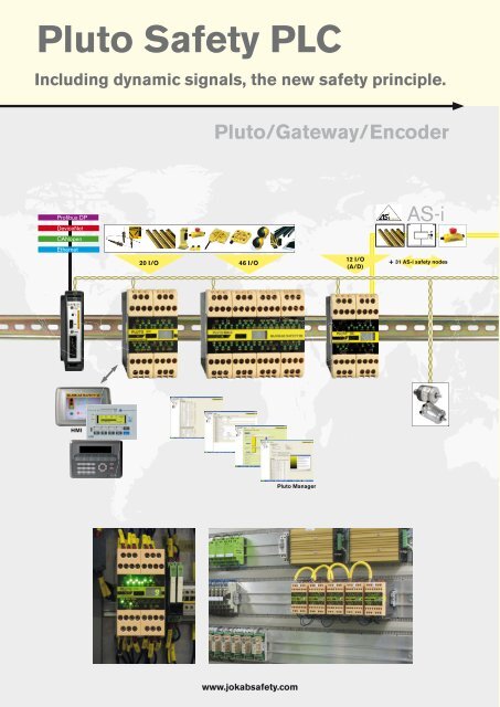
<strong>Pluto</strong> <strong>Safety</strong> <strong>PLC</strong><br />
Including dynamic signals, the new safety principle.<br />
<strong>Pluto</strong>/Gateway/Encoder<br />
Profibus DP<br />
DeviceNet<br />
CANopen<br />
Ethernet<br />
AS-i<br />
12 I/O<br />
20 I/O 46 I/O<br />
+ 31 AS-i safety nodes<br />
(A/D)<br />
HMI<br />
<strong>Pluto</strong> Manager<br />
www.jokabsafety.com
Contents<br />
Page<br />
Why you should use the <strong>Pluto</strong> safety <strong>PLC</strong> _______________________________2:2<br />
<strong>Pluto</strong> with and without a databus ______________________________________2:4<br />
_________________________________________________________2:6<br />
____________________________________________________2:8<br />
____________________________________________________ 2:10<br />
____________________________________________________ 2:11<br />
<strong>Pluto</strong> Manager ____________________________________________________ 2:12<br />
<strong>Pluto</strong> Gateway _____________________________________________________ 2:14<br />
__________________________________________________________ 2:16<br />
_________________________________________________________ 2:18<br />
_________________________________________________________ 2:20<br />
__________________________________________________________ 2:22<br />
Safe encoder ______________________________________________________ 2:24<br />
Example – Robot cell with <strong>Pluto</strong> _____________________________________ 2:28<br />
Electrical connections ______________________________________________ 2:29<br />
<strong>Pluto</strong> settings _____________________________________________________ 2:30<br />
<strong>PLC</strong> code <strong>Pluto</strong> ____________________________________________________ 2:32<br />
1<br />
2<br />
3<br />
4<br />
5<br />
6<br />
7<br />
8<br />
9<br />
10<br />
11<br />
Descriptions and examples in this book show how the products work and can be used. This does not mean that they can meet the requirements for<br />
all types of machines and processes. The purchaser/user is responsible for ensuring that the product is installed and used in accordance with the<br />
applicable regulations and standards. We reserve the right to make changes in products and product sheets without previous notice. <strong>For</strong> the latest<br />
updates, refer to www.jokabsafety.com. 2008.<br />
www.jokabsafety.com 2:1<br />
12<br />
13
Why you should<br />
have <strong>Pluto</strong> safety<br />
<strong>PLC</strong>'s.<br />
– for simplifying the design of and changes to safety systems!<br />
Approval:<br />
EN 954-1, Category 4<br />
EN 61496-1, Type 4<br />
<br />
<strong>Pluto</strong> is an ”All-Master” safety <strong>PLC</strong> concept, that simplifies<br />
the design of safety systems and achieves the highest safety<br />
<br />
<br />
between <strong>Pluto</strong> and conventional safety <strong>PLC</strong>´s is that there<br />
is no "Master-Slave" relationship between the control units<br />
connected to the safety bus. Each <strong>Pluto</strong> is a 'Master' unit and<br />
can see the other <strong>Pluto</strong>s' inputs and outputs, and can thereby<br />
make decisions about its own safety environment.<br />
This concept enables simple communication, programming<br />
and changes to the safety system. With the use of a 'Gateway'<br />
device, a <strong>Pluto</strong> can communicate with other bus systems<br />
and thereby form part of a larger network. Gateway units are<br />
available for several different bus systems, such as Profibus,<br />
<br />
safety slaves and standard slaves can be handled.<br />
<strong>Pluto</strong> offers an economic solution for both single machines<br />
and for major machine systems.<br />
Our solution with All-Master<br />
<strong>Pluto</strong> All-Master<br />
<strong>Pluto</strong> – All Master<br />
+ + <br />
<strong>Pluto</strong> All-Master<br />
<strong>Pluto</strong> All-Master<br />
4 + 4 + 4<br />
Traditional safety <strong>PLC</strong><br />
<br />
+<br />
<br />
nodes<br />
Master<br />
Safe bus<br />
4<br />
<strong>Pluto</strong> AS-i<br />
Slaves<br />
<br />
+<br />
<br />
6 + 4<br />
2:2<br />
www.jokabsafety.com
– to supervise safety devices!<br />
1<br />
Light beams Light grids/curtains <br />
devices<br />
Sensors/<br />
switches<br />
Two-hand<br />
controls<br />
Emergency<br />
stops<br />
Strips<br />
Mats<br />
2<br />
Most safety devices on the market can be connected directly<br />
to <strong>Pluto</strong> units. By using dynamic signals with sensors<br />
from Jokab <strong>Safety</strong> only one input is needed for category 4,<br />
<br />
is also possible to connect up to 10 sensors in series to a<br />
single input on <strong>Pluto</strong> according to category 4.<br />
– to save on inputs!<br />
Dynamic signals<br />
1–10 doors with one Eden per door<br />
category 4<br />
<br />
<strong>Pluto</strong><br />
has inputs for static and<br />
dynamic sensors. Several<br />
sensors can be connected<br />
to one dynamic input in<br />
accordance with category 4.<br />
<strong>For</strong> example non-contact Eden sensors, Spot light beams<br />
and Tina emergency stop buttons can all be connected in<br />
series to a single <strong>Pluto</strong> input. Even mechanical switches can<br />
be connected to the 'dynamic' safety circuit using Jokab<br />
<br />
that can be used as both inputs and outputs.<br />
<br />
Dynamic signals<br />
1-10 sensors<br />
category 4<br />
3<br />
4<br />
5<br />
6<br />
7<br />
8<br />
9<br />
<br />
IO connections<br />
<br />
<br />
<br />
both input and output at the same time (e.g. for a reset button with lamp<br />
indication)<br />
input/output<br />
Two inputs<br />
Static inputs (mechanical switches)<br />
2 for each door = category 4<br />
10<br />
11<br />
12<br />
www.jokabsafety.com 2:3<br />
13
<strong>Pluto</strong> with databus - an overview<br />
Profibus DP<br />
DeviceNet<br />
CANopen<br />
Ethernet<br />
<strong>Pluto</strong> B20<br />
20 I/O<br />
<br />
Patented<br />
HMI<br />
Gateway for two-way databus<br />
communication between <strong>Pluto</strong> and<br />
other control systems.<br />
4 independent<br />
failsafe safety outputs<br />
<strong>Pluto</strong> is an All-Master-System for dynamic and static safety circuits<br />
where the inputs and other information are shared on a databus.<br />
Several safety sensors can be connected to one input while still<br />
achieving the highest level of safety. There are also combined inputs<br />
and outputs that can be used, for example, for lamp pushbuttons<br />
where the input and output functions are used simultaneously.<br />
<strong>Pluto</strong> has inputs for all safety devices on the market, and the <strong>Pluto</strong><br />
Manager software selects how each input shall respond.<br />
HMI <br />
panel can communicate<br />
with <strong>Pluto</strong> in both directions.<br />
Connection can be<br />
made via the bus or direct<br />
to the front of the <strong>Pluto</strong>.<br />
<br />
<strong>Pluto</strong> bridge<br />
With a Gateway set up<br />
as a <strong>Pluto</strong> bridge, it is<br />
<br />
increase the databus<br />
length<br />
use different databus<br />
speeds for each section<br />
filter information from<br />
one section to reduce<br />
the databus loading on<br />
other sections.<br />
<strong>Pluto</strong> without a databus – A single <strong>Pluto</strong> can be used as a<br />
fully programmable safety logic controller.<br />
<strong>Pluto</strong> S20<br />
<strong>Pluto</strong> S46<br />
Connector expansion<br />
Patented Patented Patented<br />
Several expansion relays can be connected<br />
to a single <strong>Pluto</strong> safety output<br />
while retaining the safety level.<br />
<br />
words, they are similar to the equivalent versions with bus connections, the B20 and B46-6.<br />
2:4<br />
www.jokabsafety.com
1<br />
<strong>Pluto</strong> B46<br />
<strong>Pluto</strong> AS-i<br />
2<br />
46 I/O<br />
<strong>Safety</strong> Monitor/Master<br />
Safe bus<br />
12 I/O<br />
(A/D)<br />
+ 31 AS-i safety slaves<br />
3<br />
6 independent<br />
failsafe safety outputs<br />
Patented<br />
Patented<br />
4 independent<br />
failsafe safety outputs<br />
Approvals<br />
EN 954-1, Category 4<br />
EN ISO 13849-1, PL e<br />
EN 61496-1, Type 4<br />
EN 61508, SIL 3<br />
EN ISO 62061, SIL 3<br />
EN ISO 60204-1<br />
EN 50178<br />
EN ISO 574, Type lllc<br />
EN ISO 50295 (Only <strong>Pluto</strong> AS-i)<br />
4<br />
5<br />
Absolute encoder.<br />
8 single turn or multi<br />
turn absolute encoders<br />
can be connected directly<br />
to the safety bus.<br />
<strong>Pluto</strong> AS-i is an AS-i module which can be con-<br />
<br />
on the bus or work together with an AS-i master<br />
<br />
digital outputs, as well as safety outputs.<br />
6<br />
7<br />
Free software is available via our website, at<br />
www.jokabsafety.com!<br />
8<br />
9<br />
10<br />
<strong>Pluto</strong> Manager<br />
Programming is performed using ladder or<br />
Boolean algebra – with timers, auxiliary memory,<br />
registers, sequential programming and<br />
TÜV-approved function blocks. The program<br />
can be downloaded cost-free from the web<br />
site. Programs can be loaded via one <strong>Pluto</strong> to<br />
all the other <strong>Pluto</strong> units on the databus.<br />
11<br />
12<br />
www.jokabsafety.com 2:5<br />
13
I/O Overview - <strong>Pluto</strong><br />
IDFIX<br />
IDFIX<br />
<br />
<br />
<br />
<br />
<br />
only one input if Jokab <strong>Safety</strong> dynamic safety components are used.<br />
<br />
<br />
<br />
<br />
<br />
for electro-mechanical components such as contactors and valves.<br />
<br />
Failsafe relay outputs that are individually failsafe and individually programmable.<br />
2:6<br />
www.jokabsafety.com
Input connection<br />
<br />
short-circuits it is possible to use up to three different dynamic signals and static voltage (+24 V) to<br />
supply the inputs. The inputs are then programmed to only accept one of the signal types.<br />
<br />
thereby be able to detect a short-circuit between the channels.<br />
<br />
and the output of the sensor will be detected at the <strong>Pluto</strong> input. Category 4 can thus be achieved by using<br />
only one channel and one input.<br />
1<br />
2<br />
3<br />
Emergency<br />
stop with<br />
Tina<br />
Emergency<br />
stop with<br />
Tina<br />
Spot light<br />
beam<br />
Eden sensor<br />
4<br />
5<br />
6<br />
Two-channel system Single channel dynamic system, category 4<br />
<br />
Reset button that uses the combined input and output facility<br />
Resetting with a lamp<br />
input/output<br />
7<br />
8<br />
9<br />
(Current monitoring)<br />
24VDC<br />
<br />
A1<br />
X4<br />
10<br />
Both a lamp and a pushbutton can be connected to the same terminal. This function<br />
<br />
<br />
is intact. The lamp is only considered to be intact if sufficient current is being drawn from<br />
<br />
<br />
Examples of connector expansion<br />
11<br />
12<br />
www.jokabsafety.com 2:7<br />
13
Technical data - general<br />
<br />
<br />
<br />
Black and beige<br />
24V DC ±15%<br />
<br />
<br />
<br />
<br />
<br />
<br />
Cat. 4 in accordance with<br />
EN 954-1<br />
<br />
EN 61508/EN 62061<br />
Failsafe inputs I & IQ<br />
<br />
Current at 24 V<br />
Max. overvoltage<br />
Failsafe transistor outputs Q<br />
<br />
<br />
<br />
Failsafe relay outputs Q<br />
Max. voltage<br />
Max current<br />
Non-failsafe outputs Q<br />
<br />
<br />
Indication<br />
input/output LED<br />
<br />
<br />
also configurable as non-failsafe<br />
outputs<br />
5.1 mA<br />
<br />
–24 VDC<br />
Supply voltage - 1.5 V at 800 mA<br />
800 mA<br />
250 V AC<br />
1.5 A<br />
Transistor +24V, PNP "open<br />
collector" also configurable as<br />
failsafe inputs<br />
800 mA<br />
<br />
<br />
<strong>Pluto</strong> databus<br />
Max number of <strong>Pluto</strong> units on<br />
<br />
<br />
<br />
<br />
AS-i databus<br />
<br />
<br />
<br />
Temperature<br />
<br />
<br />
Response times<br />
Dyn. A or static input to relay<br />
<br />
Dyn. A or static input to<br />
<br />
Dyn. B or Dyn. C input to<br />
<br />
Dyn. B or Dyn. C input to<br />
<br />
Software setting "NoFilt".<br />
<br />
<br />
Additional Response times<br />
Databus between <strong>Pluto</strong> units<br />
Databus between <strong>Pluto</strong> units<br />
on error<br />
Enclosure classification<br />
<br />
<br />
<br />
CAN<br />
100, 125, 200, 250, 400, 500,<br />
800, 1000 kb/s<br />
Up to 600 m<br />
150 m at 400 kb/s<br />
M2<br />
<br />
Master<br />
<strong>Safety</strong> monitor<br />
<strong>Safety</strong> monitor & slave<br />
–10˚C to +50˚C<br />
–25˚C to +55˚C<br />
1<br />
2<br />
3<br />
The units are assembled with a gap of at least 5 mm.<br />
4<br />
5<br />
6<br />
The terminal blocks are detachable without needing to disconnect the wiring.<br />
7<br />
8<br />
<strong>Pluto</strong> S20<br />
20 I/O<br />
Non-<strong>Pluto</strong> databus<br />
<strong>Pluto</strong> B46-6<br />
46 I/O<br />
<strong>Pluto</strong> S46-6<br />
46 I/O<br />
Non-<strong>Pluto</strong> databus<br />
<strong>Pluto</strong> AS-i<br />
AS-i databus<br />
<br />
<br />
<br />
Max total load 2.5 A<br />
<br />
Max total load 2 A<br />
<br />
Max total load 2 A<br />
<br />
Max total load 2 A<br />
<br />
Max total load 2 A<br />
<br />
Max total load 2 A<br />
<br />
<br />
<br />
– – – –<br />
–<br />
<br />
–<br />
<br />
– – –<br />
<br />
100 mA 150 mA 150 mA 100 mA<br />
6 A 10A 10A 6 A<br />
45 x 84 x 118 mm 90 x 84 x 118 mm 90 x 84 x 118 mm 45 x 84 x 118 mm<br />
www.jokabsafety.com 2:9<br />
9<br />
10<br />
11<br />
12<br />
13
PLUTO ACCESSORIES<br />
Name Article no. Explanation<br />
Gate-P1<br />
<strong>Pluto</strong> Gateway<br />
Profibus<br />
<br />
Gateway for two-way communication between <strong>Pluto</strong> databus<br />
and Profibus.<br />
Gate-C1<br />
<strong>Pluto</strong> Gateway<br />
CANopen<br />
Gate-D1<br />
<strong>Pluto</strong> Gateway<br />
DeviceNet<br />
Gate-E1<br />
<strong>Pluto</strong> Gateway<br />
Ethernet<br />
<br />
<br />
<br />
Gateway for two-way communication between <strong>Pluto</strong> databus<br />
and CANopen.<br />
Gateway for two-way communication between <strong>Pluto</strong> databus<br />
and DeviceNet.<br />
Gateway for two-way communication between <strong>Pluto</strong> databus<br />
and Ethernet.<br />
IDFIX-R<br />
IDFIX-RW<br />
<br />
<br />
<br />
<br />
IDFIX-DATA<br />
<br />
R-120 Terminating resistor for <strong>Pluto</strong> databus.<br />
Operator's panel <br />
<br />
<br />
<br />
<br />
<strong>Pluto</strong> Manager Programming tool for <strong>Pluto</strong> including function blocks.<br />
Can be downloaded from www.jokabsafety.com<br />
<strong>Pluto</strong> programming<br />
cable<br />
<br />
<strong>For</strong> loading <strong>PLC</strong> programs and monitoring.<br />
Databus cable<br />
<br />
<br />
CAN-Bus cable yellow 2 x 0.50 mm ²<br />
CAN-Bus cable purple 2 x 0.50 mm ² halogen-free<br />
Absolute<br />
encoder<br />
Absolute<br />
encoder<br />
<br />
<br />
<br />
Absolute encoder model RSA 698 (multi turn)<br />
<br />
<br />
<br />
<br />
<br />
<strong>Pluto</strong> communications cable for operator's panel<br />
2:10<br />
www.jokabsafety.com
1<br />
2<br />
3<br />
4<br />
5<br />
6<br />
7<br />
8<br />
9<br />
10<br />
11<br />
12<br />
www.jokabsafety.com 2:11<br />
13
<strong>Pluto</strong> Manager<br />
Programming a project<br />
Step 1<br />
Step 2<br />
Step 3<br />
Step by step<br />
Step 1<br />
I/O configuration<br />
The inputs and outputs are configured depending on what they are connected to, static or dynamic signals,<br />
inputs and/or outputs, etc.<br />
Step 2<br />
Defining variables<br />
<br />
databus communication (GM) and registers (R). The names of the variables can be changed as required<br />
instead of the default variable names used in the <strong>PLC</strong> program.<br />
Step 3<br />
Ladder programming<br />
The programming language used in <strong>Pluto</strong> contains function blocks, certified by TÜV Rheinland, with solutions<br />
for the most common safety functions. The function blocks can be used in conjunction with standard ladder<br />
instructions. The programming language has a full instruction repertoire, similar to standard <strong>PLC</strong>s on the<br />
market, including timers, arithmetic functions, sequential programming set, etc.<br />
2:12<br />
www.jokabsafety.com
List of standards and special function blocks for <strong>Pluto</strong> Manager<br />
The safety designer has complete freedom to program the safety functions or to use TÜV-approved pre-defined safety<br />
function blocks.<br />
Blocks in the standard library (func05):<br />
1. Two-channel function with input for start<br />
2. Two-channel function with test input<br />
<br />
<br />
reset indication.<br />
4. Two-channel function with simultaneous requirement.<br />
5. Single channel function with input for start.<br />
6. Single channel function with start and test inputs.<br />
<br />
8. Two-channel function with max. time limitation<br />
(equivalent to JSHT2). Time begins to count down<br />
when both inputs are activated.<br />
9. Two-channel function with max. time limitation<br />
(equivalent to JSHT2). Time begins to count down<br />
when one of the inputs is activated.<br />
10. Single channel pulse function, e.g. for timed reset.<br />
11. Two-channel pulse function, e.g. for timed reset.<br />
12. Two single channel bypass connection functions with<br />
max. time limiting.<br />
<br />
<br />
time limiting.<br />
14. Two-channel bypass connection function with max.<br />
time limiting and simultaneous requirement.<br />
15. Two-channel safety function with max. time<br />
limited bypass connection.<br />
16. Two-hand control.<br />
<br />
18. Counter which counts down from preset value to 0.<br />
<br />
<br />
<br />
<br />
power level in Watts.<br />
<br />
power level in Watts.<br />
24. Light curtain with single cycle operation.<br />
25. Light curtain with single cycle operation and reset<br />
selection.<br />
Internet support - <strong>Pluto</strong><br />
ers,<br />
offering continuously updated product support. The<br />
<br />
<br />
<br />
<br />
requirements<br />
<br />
<br />
<br />
<br />
<br />
<br />
<br />
26. Multiplication.<br />
<br />
Other function blocks<br />
1. <strong>Safety</strong> absolute encoder.<br />
2. Electronic cam.<br />
<br />
Special function blocks:<br />
1. Program library with program block for eccentric<br />
shaft presses.<br />
2. Custom special blocks can be made available.<br />
Function block example<br />
TC1RTI<br />
Two-channel function with test and reset<br />
inputs, and reset indication.<br />
TC1RTI<br />
www.jokabsafety.com 2:13<br />
In1<br />
In2<br />
Q<br />
IndReset<br />
<br />
safety device outputs are connected.<br />
Test is a condition that must be true at the<br />
moment of switching on, and can be used<br />
for monitoring external components. Test<br />
Reset TCfault<br />
must be true before the Reset input closes,<br />
i.e. the function block cannot be initiated Test<br />
by Test.<br />
Reset is a supervised reset input and<br />
must be activated (positive flank) after the other inputs have<br />
activated for the function output to be activated.<br />
<br />
and flashes when the function block is ready for resetting.<br />
The TCfault output is activated in the case of a two-channel<br />
<br />
<br />
Description<br />
The function block acts as a conventional two-channel safety<br />
<br />
1<br />
2<br />
3<br />
4<br />
5<br />
6<br />
7<br />
8<br />
9<br />
10<br />
11<br />
12<br />
13
Use:<br />
<strong>Pluto</strong><br />
Gateway<br />
Bi-directional status information<br />
from the <strong>Pluto</strong> safety <strong>PLC</strong><br />
Profibus DP<br />
DeviceNet<br />
CANopen<br />
Ethernet<br />
Features:<br />
Two-way communication<br />
Built-in filter function, shared<br />
network<br />
<br />
Can be located anywhere in<br />
the databus<br />
Common interface with <strong>Pluto</strong><br />
Ready-made function blocks<br />
<strong>Pluto</strong> Gateway is a unit providing two-way communication<br />
between a <strong>Pluto</strong> safety <strong>PLC</strong> and other field buses. There<br />
<br />
GATE-P1 – Profibus-DP<br />
GATE-D1 – DeviceNet<br />
GATE-C1 – CANopen<br />
GATE-E1 <br />
<br />
rail, and can be connected anywhere in a <strong>Pluto</strong> databus.<br />
The unit has a common interface with <strong>Pluto</strong>, i.e. the same<br />
cabling, and the <strong>Pluto</strong> Manager PC program can be used<br />
for servicing and where necessary programming. Normal-<br />
<br />
which means that programming tools are not required to<br />
put the gateway itself into operation.<br />
<strong>For</strong> programming <strong>Pluto</strong> there are ready-made function<br />
blocks which, via a <strong>Pluto</strong> Gateway, send and receive data<br />
from the supervisory system.<br />
The GATE-D1 and GATE-C1 types, which use a CAN<br />
databus on both sides, can also usefully be used as CAN<br />
bridges where it is required to split a <strong>Pluto</strong> databus into<br />
several sections. This is particularly useful when long databus<br />
cables are needed. There is also a built-in filter function<br />
which makes it possible to block data that is not required<br />
for use on the other side of the bridge, which reduces the<br />
databus loading in the other sections and thereby permits<br />
longer databus cables.<br />
2:14<br />
www.jokabsafety.com
Gateway block schematic diagram - <strong>Pluto</strong> Gateway<br />
1<br />
2<br />
3<br />
4<br />
5<br />
6<br />
7<br />
8<br />
9<br />
10<br />
11<br />
12<br />
www.jokabsafety.com<br />
2:15<br />
13
<strong>Pluto</strong> Gateway<br />
Profibus<br />
Profibus DP<br />
<br />
<strong>Pluto</strong> safety <strong>PLC</strong>.<br />
Data from <strong>Pluto</strong><br />
-<br />
<br />
-<br />
BUS modules in the gateway, one module for each <strong>Pluto</strong><br />
unit. Local data in <strong>Pluto</strong> units can be read by a "local data”<br />
module together with the <strong>PLC</strong> codes in the supervisory<br />
system.<br />
Data to <strong>Pluto</strong><br />
<br />
non-safety-related information to a <strong>Pluto</strong> safety <strong>PLC</strong>. A total<br />
of 64 Boolean values and 8 different 16-bit registers<br />
can be transmitted. Function blocks for these functions are<br />
available in <strong>Pluto</strong> Manager.<br />
<strong>PLC</strong> function blocks<br />
<br />
into the supervisory <strong>PLC</strong> system, Jokab <strong>Safety</strong> provides<br />
ready-made function blocks for several popular brands of<br />
<strong>PLC</strong>. The function blocks make it easier to receive and<br />
send information to the <strong>Pluto</strong> system. The function blocks<br />
are supplied as open units with full access for the customer<br />
to change and add functions. These function blocks can<br />
be obtained via the Jokab <strong>Safety</strong> web site.<br />
<strong>Pluto</strong> databus LED<br />
<br />
PC port<br />
Profibus LED<br />
Profibus connector<br />
2:16<br />
www.jokabsafety.com
Technical data - Gateway Profibus<br />
Manufacturer:<br />
<br />
1<br />
Article number/ordering data: GATE-P1<br />
Databuses:<br />
<strong>Pluto</strong> databus speeds:<br />
-<strong>Pluto</strong> databus CAN (isolated)<br />
<br />
100, 200, 250, 400, 500, 800 and<br />
1000 kbit/s<br />
(automatic speed detection)<br />
2<br />
PROFIBUS speed:<br />
PROFIBUS address:<br />
Up to 12 Mbit/s (automatic speed<br />
detection)<br />
<br />
3<br />
PROFIBUS version:<br />
DP slave, DP-V0<br />
Connections:<br />
<br />
(included)<br />
nection.<br />
Bottom, 2-pole terminal for 24 V DC<br />
(included)<br />
119 mm<br />
4<br />
Status indication:<br />
<strong>Pluto</strong> databus status indication via LED<br />
<br />
Operating voltage: 24 V DC, -15% till +20%<br />
Current at 24 V: < 100 mA (recommended fuse ≤6 A)<br />
5<br />
Dimensions (w x h x d):<br />
22.5 x 101 x 119 mm<br />
Installation:<br />
<br />
Operating temperature (ambient): -10°C to + 55ºC<br />
Temperature, transport and storage: -25°C to + 55ºC<br />
101 mm<br />
6<br />
Humidity:<br />
EN 60 204-1 50% at 40ºC (ambient<br />
90% at 20ºC)<br />
Enclosure classification:<br />
<br />
<br />
22,5 mm<br />
7<br />
Gateway block schematic diagram - <strong>Pluto</strong> Profibus<br />
8<br />
9<br />
10<br />
11<br />
12<br />
www.jokabsafety.com<br />
2:17<br />
13
<strong>Pluto</strong> Gateway<br />
DeviceNet<br />
DeviceNet<br />
<br />
with <strong>Pluto</strong> safety <strong>PLC</strong>.<br />
Data from <strong>Pluto</strong><br />
Via DeviceNet a supervisory <strong>PLC</strong> system can have access<br />
<br />
<br />
”implicit” messages. Local data in <strong>Pluto</strong> units can be read<br />
via DeviceNet ”explicit” messages.<br />
Data to <strong>Pluto</strong><br />
Via DeviceNet a supervisory <strong>PLC</strong> system can transmit nonsafety-related<br />
information to a <strong>Pluto</strong> safety <strong>PLC</strong>. A total of<br />
64 Boolean values and 8 different 16-bit registers can be<br />
transmitted (via DeviceNet ”implicit” or ”explicit” messages).<br />
Function blocks for these commands are available in<br />
<strong>Pluto</strong> Manager.<br />
<strong>Pluto</strong> bridge<br />
A GATE-D1 can also be used to advantage as a CAN<br />
bridge when it is required to divide a <strong>Pluto</strong> databus into<br />
several sections. This is particularly useful when long databus<br />
cables are needed.<br />
There is also a built-in filter function which makes it possible<br />
to block any data that is not required for use on the<br />
other side of the bridge, which reduces the databus loading<br />
in the other sections and thereby permits longer databus<br />
cables.<br />
ABB Robotics IRC5<br />
<br />
<br />
that describes this integration can be obtained via the Jokab<br />
<strong>Safety</strong> web site.<br />
<strong>Pluto</strong> databus LED<br />
<br />
PC port<br />
DeviceNet LED<br />
DeviceNet connector<br />
2:18<br />
www.jokabsafety.com
Technical data - DeviceNet<br />
Manufacturer<br />
<br />
1<br />
Article number/ordering data: GATE-D1<br />
Databuses:<br />
<strong>Pluto</strong> databus speeds:<br />
-<strong>Pluto</strong> databus CAN (isolated)<br />
-DeviceNet CAN (isolated)<br />
100, 200, 250, 400, 500, 800 and<br />
1000 kbit/s<br />
(automatic speed detection)<br />
2<br />
DeviceNet speeds:<br />
DeviceNet address:<br />
<br />
switch)<br />
<br />
3<br />
DeviceNet Version:<br />
<br />
Connections:<br />
<br />
(included)<br />
Front, 5-pole terminal for DeviceNet<br />
(included)<br />
Bottom, 2-pole terminal for 24 V DC<br />
(included)<br />
119 mm<br />
4<br />
Status indications:<br />
<strong>Pluto</strong> databus status indication via LED<br />
DeviceNet MNS status indication via<br />
LED<br />
Operating voltage: 24 V DC, -15% till +20%<br />
5<br />
Current at 24 V: < 100 mA (recommended fuse ≤6 A)<br />
Dimensions (w x h x d):<br />
22.5 x 101 x 119 mm<br />
Installation:<br />
<br />
Operating temperature (ambient): -10°C to + 55ºC<br />
Temperature,<br />
transport and storage: -25°C to + 55ºC<br />
101 mm<br />
6<br />
Humidity:<br />
Enclosure classification:<br />
EN 60 204-1 50% at 40ºC (ambient<br />
90% at 20ºC)<br />
<br />
<br />
22,5 mm<br />
7<br />
Gateway block schematic diagram - <strong>Pluto</strong> DeviceNet<br />
8<br />
9<br />
10<br />
11<br />
12<br />
www.jokabsafety.com 2:19<br />
13
<strong>Pluto</strong> Gateway<br />
CANopen<br />
CANopen<br />
<br />
with <strong>Pluto</strong> safety <strong>PLC</strong>.<br />
Data from <strong>Pluto</strong><br />
Via CANopen a supervisory <strong>PLC</strong> system can have access<br />
<br />
<br />
<br />
<br />
the supervisory system.<br />
Data to <strong>Pluto</strong><br />
Via CANopen a supervisory <strong>PLC</strong> system can send nonsafety-related<br />
information to a <strong>Pluto</strong> safety <strong>PLC</strong>. A total of<br />
64 Boolean values and 8 different 16-bit registers can be<br />
<br />
blocks for these commands are available in <strong>Pluto</strong> Manager.<br />
<strong>Pluto</strong> bridge<br />
A GATE-C1 can also be used to advantage as a CAN<br />
bridge when it is required to divide a <strong>Pluto</strong> databus into<br />
several sections. This is particularly useful when long databus<br />
cables are needed.<br />
There is also a built-in filter function which makes it possible<br />
to block any data that is not required for use on the<br />
other side of the bridge, which reduces the databus loading<br />
in the other sections and thereby permits longer databus<br />
cables.<br />
<strong>Pluto</strong> databus LED<br />
<br />
PC port<br />
CANopen LED<br />
<br />
2:20<br />
www.jokabsafety.com
Technical data - Gateway CANopen<br />
Manufacturer<br />
<br />
1<br />
Article number/ordering data: GATE-C1<br />
Databuses:<br />
<strong>Pluto</strong> databus speeds:<br />
-<strong>Pluto</strong> databus CAN (isolated)<br />
-CANopen CAN (isolated)<br />
100, 200, 250, 400, 500, 800 and<br />
1000 kbit/s<br />
(automatic speed detection)<br />
2<br />
CANopen speeds:<br />
<br />
switch)<br />
10, 20, 50, 100, 125, 250, 500, 800<br />
and 1000 kbit/s (via software)<br />
3<br />
CANopen address:<br />
<br />
CANopen version:<br />
Connections:<br />
Status indications:<br />
”Version 4.02 of the CiA Draft Standard<br />
<br />
<br />
(included)<br />
Front, 5-pole terminal for CANopen<br />
(included)<br />
Bottom, 2-pole terminal for 24 V DC<br />
(included)<br />
<strong>Pluto</strong> databus status indication via LED<br />
CANopen status indication via LED<br />
119 mm<br />
4<br />
5<br />
Operating voltage: 24 V DC, -15% till +20%<br />
Current at 24 V: < 100 mA (recommended fuse ≤6 A)<br />
Dimensions (w x h x d):<br />
22.5 x 101 x 119 mm<br />
Installation:<br />
<br />
101 mm<br />
6<br />
Operating temperature (ambient): -10°C to + 55ºC<br />
Temperature, transport and storage: -25°C to + 55ºC<br />
Humidity:<br />
EN 60 204-1 50% at 40ºC (ambient<br />
90% at 20ºC)<br />
Enclosure classification:<br />
<br />
<br />
22,5 mm<br />
7<br />
Gateway block schematic diagram - <strong>Pluto</strong> CANopen<br />
8<br />
9<br />
10<br />
11<br />
12<br />
www.jokabsafety.com<br />
2:21<br />
13
<strong>Pluto</strong> Gateway<br />
Ethernet<br />
Ethernet<br />
cation<br />
with <strong>Pluto</strong> safety <strong>PLC</strong>.<br />
Protocol<br />
<br />
from and to <strong>Pluto</strong> safety <strong>PLC</strong>s via Ethernet protocols Eth-<br />
<br />
<br />
<br />
server and a terminal server.<br />
Data from <strong>Pluto</strong><br />
Via one of the Ethernet protocols a supervisory <strong>PLC</strong> system<br />
<br />
-<br />
<br />
Local data in <strong>Pluto</strong> units can be read by special commands<br />
together with the <strong>PLC</strong> codes in the supervisory system.<br />
Data to <strong>Pluto</strong><br />
Via the Ethernet protocol a supervisory <strong>PLC</strong> system can<br />
transmit non-safety-related information to a <strong>Pluto</strong> safety<br />
<strong>PLC</strong>. A total of 64 Boolean values and 8 different 16-bit<br />
registers can be transmitted. Function blocks for these<br />
functions are available in <strong>Pluto</strong> Manager.<br />
<strong>Pluto</strong> databus LED<br />
<br />
PC port<br />
Ethernet LED<br />
Ethernet connector<br />
2:22<br />
www.jokabsafety.com
C L<br />
IQ12<br />
C H I1 I3<br />
I0<br />
IQ14<br />
I2<br />
IQ16<br />
I4<br />
I5 I7 IQ11 Q3<br />
Q0<br />
IQ10<br />
Q1<br />
IQ13 IQ15 IQ17 ID 0V +24V<br />
I6<br />
Q2<br />
C L<br />
IQ12<br />
C H I1 I3<br />
I0<br />
IQ14<br />
I2<br />
IQ16<br />
I4<br />
I5 I7 IQ11 Q3<br />
Q0<br />
IQ10<br />
Q1<br />
IQ13 IQ15 IQ17 ID 0V +24V<br />
I6<br />
Q2<br />
PLUTO<br />
BUS<br />
K<br />
PR<br />
Mod<br />
Status<br />
Net<br />
Status<br />
C L<br />
IQ12<br />
C H I1 I3<br />
I0<br />
IQ14<br />
I2<br />
IQ16<br />
I4<br />
I5 I7 IQ11 Q3<br />
Q0<br />
IQ10<br />
Q1<br />
IQ13 IQ15 IQ17 ID 0V +24V<br />
I6<br />
Q2<br />
Technical data - Ethernet<br />
Manufacturer<br />
<br />
Article number/<br />
ordering data: GATE-E1<br />
<strong>Pluto</strong> databus<br />
CAN (isolated)<br />
<strong>Pluto</strong> databus speeds 100, 200, 250, 400, 500, 800<br />
and 1000 kbit/s<br />
(automatic speed detection)<br />
Ethernet<br />
10/100 Mbit/s<br />
Half and full duplex<br />
Ethernet protocol<br />
Status from and to <strong>Pluto</strong> safety<br />
<strong>PLC</strong><br />
<br />
<br />
- Modbus TCP<br />
<br />
EtherNet/IP<br />
PROFINET<br />
Modbus TCP<br />
Binary server (TCP/IP)<br />
Web server<br />
Note that certain combinations<br />
of server protocols cannot be<br />
used simultaneously.<br />
<br />
configuration<br />
- Web server<br />
<br />
<br />
<br />
<br />
<br />
<br />
According to the Modbus organisation,<br />
version 1.0b (approx. 20<br />
messages per second).<br />
<br />
status from/to the <strong>Pluto</strong> system.<br />
<br />
addresses.<br />
Terminal server (TCP/IP) Simple server with the same<br />
commands as via the serial programming<br />
port in the unit.<br />
IP address<br />
Static sharing via web server or<br />
via programming port.<br />
Gateway configuration <br />
<br />
<br />
Connections<br />
<br />
databus (included)<br />
Front, Ethernet connection via<br />
RJ-45 (screened cable cat. 5e<br />
FTP)<br />
Bottom, 2-pole terminal for 24 V<br />
DC (included)<br />
Status indications<br />
<strong>Pluto</strong> databus status indication<br />
via LED (<strong>Pluto</strong> databus)<br />
Ethernet module status indication<br />
via LED (Mod Status)<br />
Ethernet network status indication<br />
via LED (Net Status)<br />
Operating voltage 24 V DC, -15 % till +20 %<br />
Current at 24 V<br />
< 150 mA (recommended fuse<br />
≤6 A)<br />
Dimensions (w x h x d): <br />
Installation<br />
<br />
Operating temperature<br />
(ambient) -10°C to + 55ºC<br />
Temperature,<br />
transport and storage -25°C to + 55ºC<br />
Humidity EN 60 204-1 50 % at 40ºC<br />
(ambient 90 % at 20ºC)<br />
Enclosure classification <br />
<br />
1<br />
2<br />
3<br />
4<br />
5<br />
6<br />
7<br />
8<br />
Gateway block schematic diagram - <strong>Pluto</strong> Ethernet<br />
<strong>PLC</strong><br />
Ethernet, non safety<br />
119 mm<br />
9<br />
GATE-E1<br />
10<br />
Modbus TCP<br />
EtherNet/IP<br />
PROFINET<br />
<strong>Pluto</strong> CAN bus, safety<br />
Gateway<br />
101 mm<br />
11<br />
12<br />
<br />
<strong>Pluto</strong> <strong>Pluto</strong> <strong>Pluto</strong><br />
www.jokabsafety.com 2:23<br />
13
<strong>Pluto</strong><br />
Safe Encoder<br />
Use:<br />
Safe position and speed determination<br />
of machine movements.<br />
Features:<br />
High resolution<br />
Selectable resolution<br />
Connected directly to the <strong>Pluto</strong><br />
databus<br />
Ready-made function blocks<br />
Rotational absolute value sensor for safe<br />
positioning<br />
Together with a <strong>Pluto</strong> safety <strong>PLC</strong>, this rotational absolute<br />
encoder can be used for safe position determination. This<br />
is particularly useful in the case of such equipment as gantry<br />
robots, industrial robots, etc. Also in eccentric shaft<br />
presses, existing cam mechanisms can be replaced by absolute<br />
value position sensors for safe positioning. The sensors<br />
are available in single and multi-turn versions.<br />
Up to 16 absolute encoders can be connected to a <strong>Pluto</strong><br />
CAN databus. A <strong>Pluto</strong> on the databus reads the sensor<br />
values, which are evaluated. With a special function block<br />
in the <strong>PLC</strong> code, it is possible to design two-channel solutions<br />
with the sensors. The user can obtain safe values for<br />
position and speed from these values. This enables supervision<br />
of stationary and overspeed conditions.<br />
The absolute value sensors are standard sensors with<br />
modified software to meet the safety requirements.<br />
Example of an application where 2 sensors provide safe position determination in a gantry robot.<br />
2:24<br />
www.jokabsafety.com
Technical data – Safe Encoder RSA 597<br />
Manufacturer<br />
<br />
Article number/ordering data: <br />
Ambient temperature<br />
<br />
Temperature, transport and storage <br />
Ingress protection class<br />
<br />
At shaft inlet<br />
<br />
Vibration (55 to 2000 Hz)<br />
2 <br />
60068-2-6<br />
Shock (6ms)<br />
< 2,000 m/s 2 <br />
<br />
Material, enclosure<br />
Aluminium<br />
Surface treatment<br />
Painted and chromed or anodised<br />
Weight<br />
<br />
Accuracy and resolution<br />
Resolution<br />
<br />
Accuracy<br />
± ½ LSB (Least Significant Bit)<br />
Operating voltage<br />
<br />
Polarity-protected<br />
<br />
Short-circuit protected<br />
<br />
Databus speed<br />
5 kbit/s - 1 Mbit/s, preset at 500kbit/s<br />
Address input<br />
Active low<br />
Code type<br />
Binary<br />
Programmable functions<br />
Resolution, 0 position<br />
Direction, Databus speed<br />
Current consumption<br />
50 mA at 24V dc<br />
Max current consumption<br />
100 mA<br />
1<br />
2<br />
3<br />
4<br />
5<br />
6<br />
7<br />
8<br />
9<br />
10<br />
11<br />
12<br />
www.jokabsafety.com 2:25<br />
13
Technical data – Safe Encoder RSA 698<br />
Manufacturer<br />
<br />
Article number/ordering data: <br />
Ambient temperature<br />
<br />
Temperature, transport and storage <br />
Ingress protection class<br />
<br />
At shaft inlet<br />
<br />
Vibration (55 to 2000 Hz)<br />
< 100 m/s 2 <br />
60068-2-6<br />
Shock (6ms)<br />
< 2,000 m/s 2 <br />
<br />
Material, enclosure<br />
Aluminium<br />
Surface treatment<br />
Anodised<br />
Weight<br />
Approx. 400g<br />
Accuracy and resolution<br />
Resolution, total<br />
25 bit<br />
<br />
12 bits, 4096 rotations<br />
Accuracy<br />
± 1 LSB (Least Significant Bit)<br />
Operating voltage<br />
<br />
Polarity-protected<br />
<br />
Short-circuit protected<br />
<br />
Databus speed<br />
10 kbit/s - 1 Mbit/s<br />
Code type<br />
Binary<br />
Programmable functions<br />
Resolution, 0 position<br />
Current consumption<br />
50 mA at 24V dc<br />
Max current consumption<br />
100 mA<br />
2:26<br />
www.jokabsafety.com
Safe Encoder<br />
Function block for a single-turn encoder<br />
that generates safe position and speed<br />
values from two absolute encoders.<br />
Function<br />
The block reads and evaluates one absolute<br />
encoders. The position value is sent to<br />
the 'Position' output. The 'Speed' output<br />
is the average value for the speed, at the<br />
<br />
<br />
applications the values of 'Position' and<br />
'Speed' are used in conjunction with the<br />
<br />
Descriptions of inputs and outputs<br />
<br />
<br />
<br />
(max 2% of Range)<br />
<br />
<br />
the position values are within the margin set by 'MaxDiff'<br />
<br />
<br />
<br />
<br />
NOTE! Position values from single encoders are only available<br />
<br />
NOTE! <br />
<br />
1<br />
2<br />
3<br />
4<br />
Safe Encoder<br />
Multiturn<br />
Function block for a multi-turn encoder<br />
that generates safe position and speed<br />
values from two absolute encoders.<br />
Operative system 2.4.4 or higher is<br />
required.<br />
Function<br />
The block reads and evaluates two<br />
absolute encoders. The average value for<br />
the two sensors is calculated and sent to<br />
the 'Position' output. The 'Speed' output<br />
is the average value for the speed, at the<br />
rate of pulses/10 ms. The block monitors<br />
that the encoder position values do not<br />
differ by more than the input value set by<br />
-<br />
<br />
the values of 'Position' and 'Speed' are<br />
<br />
Encoder Cam<br />
Function block for electronic cam gear.<br />
Function<br />
<br />
input register 'PosReg' is within the limits<br />
for ’MinPos’ and ’MaxPos’.<br />
<br />
that defines the sensor's zero position.<br />
Position
Example – Robot cell with <strong>Pluto</strong><br />
Description:<br />
The example describes a processing machine served by<br />
a robot. The machine safety system consists of one <strong>Pluto</strong><br />
to which all protection has been connected. The robot has<br />
been equipped with a <strong>Pluto</strong> to which the cell protection<br />
has been connected. The <strong>Pluto</strong> for the machine has been<br />
connected via a databus cable to the robot's <strong>Pluto</strong> so that<br />
common functions, such as emergency stop, can be used<br />
by the whole cell.<br />
Function:<br />
Emergency stop takes priority and will stop both the machine<br />
and the robot. The machine hatch acts as the zone<br />
divider, when the hatch is closed the machine forms one<br />
zone and the robot another zone. When the machine hatch<br />
is open, both the machine and the robot belong to the<br />
<br />
is open, the machine and the robot will both stop, but if the<br />
machine hatch is closed, only the robot will be stopped.<br />
After the door has been opened, the system must be reset<br />
by means of the reset button on the outside of the door.<br />
Emergency stop is reset when the pressed-in button is<br />
ever<br />
start immediately on resetting the emergency stop or<br />
the door.<br />
2:28<br />
www.jokabsafety.com
Electrical connections<br />
1<br />
Apparatus<br />
enclosure<br />
Robot<br />
enclosure<br />
<strong>Pluto</strong> databus<br />
Electrical equipment<br />
enclosure for machinery<br />
2<br />
Emergency stop<br />
Door<br />
Emergency stop<br />
Machine<br />
emergency<br />
stop<br />
<strong>Safety</strong> interlock switch<br />
3<br />
Machine<br />
protective<br />
stop<br />
4<br />
Robot<br />
Emergency stop<br />
Robot<br />
Autostop<br />
5<br />
<br />
<br />
<br />
Matning<br />
<br />
<br />
Supply<br />
6<br />
7<br />
8<br />
9<br />
10<br />
11<br />
12<br />
www.jokabsafety.com 2:29<br />
13
<strong>Pluto</strong> 0 settings<br />
<strong>Pluto</strong> 0<br />
<br />
<br />
<br />
<br />
<br />
<br />
<br />
<br />
<br />
<br />
<br />
<br />
<br />
<br />
<br />
<br />
<br />
<br />
2:30<br />
www.jokabsafety.com
<strong>Pluto</strong> 1 settings<br />
1<br />
<strong>Pluto</strong> 1<br />
<br />
<br />
<br />
<br />
<br />
<br />
<br />
<br />
<br />
<br />
<br />
<br />
<br />
<br />
<br />
<br />
<br />
<br />
<br />
<br />
<br />
<br />
the machine hatch.<br />
<br />
<br />
2<br />
3<br />
4<br />
5<br />
6<br />
7<br />
8<br />
9<br />
10<br />
11<br />
12<br />
www.jokabsafety.com 2:31<br />
13
<strong>PLC</strong> code <strong>Pluto</strong> 0<br />
1<br />
Start<br />
2<br />
Two-channel supervision with automatic reset emergency stop at the door.<br />
<br />
<br />
In1<br />
TC1S<br />
Q<br />
<br />
<br />
E-stop_kanal_2<br />
<br />
In2<br />
Start<br />
GM0.1 = E-stop_OK_mem<br />
Auxiliary memory for emergency stop OK<br />
I0.0 = E-stop_kanal_1 Channel 1 from the emergency stop button<br />
I0.1 = E-stop_kanal_2 Channel 2 from the emergency stop button<br />
3<br />
Emergency stop for the robot<br />
When the emergency stop is activated, the robot will perform an emergency stop.<br />
To reset the safety features, the emergency stop button must be reset.<br />
<br />
<br />
<br />
GM0.1 = E-stop_OK_mem<br />
Auxiliary memory for emergency stop OK<br />
GM1.1 = E-stop_machine_OK_mem Global auxiliary memory from two-channel supervision of the emergency stop on the machine.<br />
Q0.3 = Robot_NS_OK Emergency stop for the robot<br />
4<br />
Automatic stop for the robot<br />
When the door of the cell opens the robot is set to automatically stop.<br />
To reset the safety features, the door must be closed and then the reset signal given.<br />
<br />
<br />
In1<br />
ResetT<br />
Q<br />
<br />
<br />
Reset<br />
<br />
Reset<br />
IndReset<br />
Reset_ind_1_mem<br />
<br />
Test<br />
.2 = Door<br />
Signal from the door sensor<br />
I1.15 = Reset Reset button Reset<br />
M0.0 = Reset_ind_1_mem Auxiliary memory for indication in the reset button<br />
Q0.2 = Robot_Autostopp_OK Automatic stop for the robot<br />
5<br />
<br />
Summary of local memories that shall generate the signal in the reset lamp.<br />
The global memory is then used in the <strong>Pluto</strong> where the output is.<br />
Reset_ind_1_mem<br />
Reset_ind_1_mem<br />
M0.0 GM0.0<br />
GM0.0 = Reset_ind_mem<br />
Collective memory for indication in the reset button<br />
M0.0 = Reset_ind_1_mem Auxiliary memory 1 for indication in the reset button<br />
2:32<br />
www.jokabsafety.com
6<br />
<br />
<br />
To generate an alarm, a UE code (UE = User Error) can be shown on the <strong>Pluto</strong>'s display.<br />
This alarm code is selected by a value of between 200 and 299 being written into the <strong>Pluto</strong>'s display register.<br />
SR_ErrorCode = 0 is used as a condition to prioritise an internal alarm from the unit.<br />
<br />
<br />
<br />
GM1.0 = Machine hatch_OK_mem Global auxiliary memory from two-channel supervision of the safety interlock switch in the machine hatch.<br />
SR0.10 = SR_<strong>Pluto</strong>Display <strong>Pluto</strong> display figure<br />
SR0.11 = SR_ErrorCode Error code. <strong>For</strong> user error 200 + no<br />
1<br />
2<br />
3<br />
7<br />
8<br />
<br />
Alarm 02 – Door open.<br />
To generate an alarm, a UE code (UE = User Error) can be shown on the <strong>Pluto</strong>'s display.<br />
This alarm code is selected by a value of between 200 and 299 being written into the <strong>Pluto</strong>'s display register.<br />
SR_ErrorCode = 0 is used as a condition to prioritise an internal alarm from the unit.<br />
Door SR_ErrorCode = 0 SR_<strong>Pluto</strong>Display = 202<br />
<br />
10.2 = Door Signal from the door sensor<br />
SR0.10 = SR_<strong>Pluto</strong>Display<br />
<strong>Pluto</strong> display figure<br />
SR0.11 = SR_Errorcode<br />
Error code. <strong>For</strong> user error 200 + no<br />
<br />
Alarm 01 - Emergency stop activated<br />
To generate an alarm, a UE code (UE = User Error) can be shown on the <strong>Pluto</strong>'s display.<br />
This alarm code is selected by a value of between 200 and 299 being written into the <strong>Pluto</strong>'s display register.<br />
SR_ErrorCode = 0 is used as a condition to prioritise an internal alarm from the unit.<br />
<br />
SR0.11 = 0 SR0.10 = 201<br />
4<br />
5<br />
6<br />
7<br />
GM0.1 = E-stop_OK_mem<br />
SR0.10 = SR_<strong>Pluto</strong>Display<br />
SR0.11 = SR_ErrorCode<br />
Auxiliary memory for emergency stop OK<br />
<strong>Pluto</strong> display figure<br />
Error code. <strong>For</strong> user error 200 + no<br />
8<br />
9<br />
10<br />
11<br />
12<br />
www.jokabsafety.com 2:33<br />
13
<strong>PLC</strong> code <strong>Pluto</strong> 1<br />
1<br />
Start<br />
2<br />
Two-channel supervision with automatic reset of the emergency stop on the machine.<br />
<br />
<br />
In1<br />
TC1S<br />
<br />
<br />
E-stop_machine_kanal_2<br />
<br />
In2<br />
Start<br />
GM1.1 = E-stop_machine_OK_mem Global auxiliary memory from two-channel supervision of the emergency stop on the machine.<br />
I0.0 = E-stop_machine_kanal_1 Channel 1 from the emergency stop button on the machine<br />
I0.1 = E-stop_machine_kanal_2 Channel 2 from the emergency stop button on the machine<br />
3<br />
Two-channel supervision of the machine hatch switch.<br />
The switch has alternating contacts and the variable name shows the contact arrangement for the respect signals when the key is in the sensor.<br />
- Machine hatch_NC gives a signal<br />
<br />
<br />
<br />
<br />
<br />
In1<br />
TC1S<br />
Q<br />
<br />
<br />
In2<br />
Start<br />
GM1.0 = Machine hatch_OK_mem Global auxiliary memory from two-channel supervision of the safety interlock switch in the machine hatch.<br />
I1.11 = Machine hatch_NC Channel 1 from the safety interlock switch<br />
I1.12 = Machine hatch_NO Channel 2 from the safety interlock switch<br />
4<br />
Emergency machine stop.<br />
When the emergency stop is activated, the machine will perform an emergency stop.<br />
To reset the safety features, the emergency stop button must be reset.<br />
<br />
<br />
<br />
GM0.1 = E-stop_OK_mem<br />
Auxiliary memory for emergency stop OK<br />
GM1.1 = E-stop_machine_OK_mem Global auxiliary memory from two-channel supervision of the emergency stop on the machine.<br />
Q1.0 = Maskin_E-stop_OK Emergency machine stop.<br />
5<br />
Protective machine stop.<br />
When the protective stop is activated, the machine will stop.<br />
<br />
To reset the safety features, the door or the machine hatch must be closed and then the reset signal given.<br />
<br />
<br />
In1<br />
ResetT<br />
Q<br />
<br />
<br />
Door<br />
<br />
IndReset<br />
Reset_ind_2_mem<br />
<br />
Reset<br />
<br />
Reset<br />
Test<br />
2:34<br />
www.jokabsafety.com
6<br />
GM1.0 = Machine hatch_OK_mem Global auxiliary memory from two-channel supervision of the safety interlock switch in the machine hatch.<br />
I0.2 = Door Signal from the door sensor<br />
I1.15 = Reset Reset button Reset<br />
M1.0 = Reset_Ind_2_mem Auxiliary memory 2 for indication in the reset button<br />
Q1.1 = Maskin_skyddstop_OK Protective machine stop.<br />
<br />
Summary of memories that shall generate the signal in the reset lamp.<br />
<br />
<br />
<br />
M1.0<br />
GM0.0 = Reset_Ind_mem<br />
Collective memory for indication in the reset button<br />
M1.0 = Reset_Ind_2_mem Auxiliary memory 2 for indication in the reset button<br />
Q1.15 = Reset_Ind Indication lamp in the reset button.<br />
<br />
<br />
1<br />
2<br />
3<br />
4<br />
7<br />
8<br />
9<br />
<br />
<br />
To generate an alarm, a UE code (UE = User Error) can be shown on the <strong>Pluto</strong>'s display.<br />
This alarm code is selected by a value of between 200 and 299 being written into the <strong>Pluto</strong>'s display register.<br />
SR_ErrorCode = 0 is used as a condition to prioritise an internal alarm from the unit.<br />
<br />
<br />
GM1.0 = Machine hatch_OK_mem Global auxiliary memory from two-channel supervision of the safety interlock switch in the machine hatch.<br />
SR1.10 = SR_<strong>Pluto</strong>Display <strong>Pluto</strong> display figure<br />
SR1.11 = SR_ErrorCode Error code. <strong>For</strong> user error 200 + no<br />
<br />
Alarm 02 – Door open.<br />
To generate an alarm, a UE code (UE = User Error) can be shown on the <strong>Pluto</strong>'s display.<br />
This alarm code is selected by a value of between 200 and 299 being written into the <strong>Pluto</strong>'s display register.<br />
SR_ErrorCode = 0 is used as a condition to prioritise an internal alarm from the unit.<br />
Door SR_ErrorCode = 0 SR_<strong>Pluto</strong>Display = 202<br />
<br />
I0.1 = Door Signal from the door sensor<br />
SR1.10 = SR_<strong>Pluto</strong>Display<br />
<strong>Pluto</strong> display figure<br />
SR1.11 = SR_ErrorCode<br />
Error code. <strong>For</strong> user error 200 + no<br />
<br />
Alarm 01 - Emergency stop activated.<br />
To generate an alarm, a UE code (UE = User Error) can be shown on the <strong>Pluto</strong>'s display.<br />
This alarm code is selected by a value of between 200 and 299 being written into the <strong>Pluto</strong>'s display register.<br />
SR_ErrorCode = 0 is used as a condition to prioritise an internal alarm from the unit.<br />
<br />
SR1.11 = 0 SR1.10 = 201<br />
5<br />
6<br />
7<br />
8<br />
9<br />
10<br />
11<br />
GM0.1 = E-stop_OK_mem<br />
SR1.10 = SR_<strong>Pluto</strong>Display<br />
SR1.11 = SR_ErrorCode<br />
Auxiliary memory for emergency stop OK<br />
<strong>Pluto</strong> display figure<br />
Error code. <strong>For</strong> user error 200 + no<br />
12<br />
www.jokabsafety.com 2:35<br />
13