

DEMO - 1959 Ford Thunderbird Shop Manual - ForelPublishing.com
DEMO - 1959 Ford Thunderbird Shop Manual - ForelPublishing.com
DEMO - 1959 Ford Thunderbird Shop Manual - ForelPublishing.com

Create successful ePaper yourself
Turn your PDF publications into a flip-book with our unique Google optimized e-Paper software.
PART 1-1 -GENERAL ENGINE SERVICE 1-9<br />
TESTS AND ADJUSTMENTS (ENGINE INSTALLED)<br />
CAMSHAFT LOBE LIFT<br />
1. Remove the valve rocker arm<br />
shaft<br />
assembly and install a solid<br />
tappet-type push rod in the push rod<br />
bore of the camshaft lobe to be<br />
checked.<br />
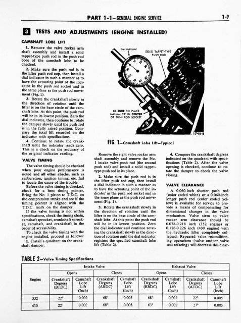
2. Make sure the push rod is in<br />
the lifter push rod cup, then install a<br />
dial indicator in such a manner as to<br />
have the actuating point of the indi<br />
cator in the push rod socket and in<br />
the same plane as the push rod move<br />
ment (Fig. 1).<br />
3. Rotate the crankshaft slowly in<br />
the direction of rotation until the<br />
lifter is on the base circle of the cam<br />
shaft lobe. At this point, the push rod<br />
will be in its lowest position. Zero the<br />
dial indicator, then continue to rotate<br />
the damper slowly until the push rod<br />
is in the fully raised position. Com<br />
pare the total lift recorded on the<br />
indicator with specifications.<br />
4. Continue to rotate the crank<br />
shaft until the indicator reads zero.<br />
This is a check on the accuracy of<br />
the original indicator reading.<br />
VALVE TIMING<br />
The valve timing should be checked<br />
when poor engine performance is<br />
noted and all other checks, such as<br />
carburetion, ignition timing, etc. fail<br />
to locate the cause of the trouble.<br />
Before the valve timing is checked,<br />
check for a bent timing pointer.<br />
Bring the No. 1<br />
piston to T.D.C. on<br />
the <strong>com</strong>pression stroke and see if the<br />
timing<br />
T.D.C. mark on the damper.<br />
pointer is<br />
If the valve timing<br />
aligned with the<br />
is not within<br />
specifications, check the timing chain,<br />
camshaft sprocket, crankshaft sprock<br />
et, camshaft, and crankshaft in the<br />
order of accessibility.<br />
To check the valve timing<br />
with the<br />
engine installed, proceed as follows:<br />
1. Install a quadrant on the crank<br />
shaft damper.<br />
BE SURE TO PLACE<br />
Indicator TIP IN CENTER<br />
OF PUSH ROD SOCKET<br />
FIG. 1 Camshaft Lobe LiftTypical<br />
Remove the right valve rocker arm<br />
shaft assembly and remove the No.<br />
1 intake valve push rod (the second<br />
push rod) and install a solid tappettype<br />
push rod in its place.<br />
2. Make sure the push rod is in<br />
the lifter push rod cup, then install<br />
a dial indicator in such a manner as<br />
to have the actuating point of the in<br />
dicator in the push rod socket and in<br />
the same plane as the push rod move<br />
ment (Fig. 1).<br />
3. Rotate the crankshaft slowly in<br />
the direction of rotation until the<br />
lifter is on the base circle of the cam<br />
shaft lobe. At this point the push rod<br />
will be in its lowest position. Zero<br />
the dial indicator and continue rotat<br />
ing the crankshaft slowly in the direc<br />
tion of rotation until the dial indicator<br />
registers the specified camshaft lobe<br />
lift (Table 2).<br />
1748-B<br />
4. Compare the crankshaft degrees<br />
indicated on the quadrant with speci<br />
fications (Table 2). After the valve<br />
opening is checked, continue to ro<br />
tate the damper to check the valve<br />
closing.<br />
VALVE<br />
CLEARANCE<br />
A 0.060-inch shorter push rod<br />
(color coded white)<br />
or a 0.060-inch<br />
longer push rod (color coded yel<br />
low) is available for service to pro<br />
vide a means of <strong>com</strong>pensating for<br />
dimensional changes in the valve<br />
mechanism. Valve stem to valve<br />
rocker arm clearance should be<br />
0.078-0.218 inch (352 engine) or<br />
0.126-0.226 inch (430 engine) with<br />
the hydraulic lifter <strong>com</strong>pletely col<br />
lapsed. Repeated valve recondition<br />
ing operations (valve and/or valve<br />
seat refacing) will decrease this clear-<br />
TABLE 2 Valve Timing Specifications<br />
Intake Valve<br />
Exhaust Valve<br />
Opens Closes Opens Closes<br />
Engine<br />
Crankshaft<br />
Degrees<br />
(BTDC)<br />
Camshaft<br />
Lobe<br />
Lift<br />
(Inch)<br />
Crankshaft<br />
Degrees<br />
(ABDC)<br />
Camshaft<br />
Lobe<br />
Lift<br />
(Inch)<br />
Crankshaft<br />
Degrees<br />
(BBDC)<br />
Camshaft<br />
Lobe<br />
Lift<br />
(Inch)<br />
Crankshaft<br />
Degrees<br />
(ATDC)<br />
Camshaft<br />
Lobe<br />
Lift<br />
(Inch)<br />
352<br />
22<br />
0.002<br />
68<br />
0.005<br />
68<br />
0.002<br />
22<br />
0.005<br />
430<br />
22<br />
0.002<br />
68<br />
0.005<br />
63<br />
0.002<br />
27<br />
0.005


