

DEMO - 1959 Ford Thunderbird Shop Manual - ForelPublishing.com
DEMO - 1959 Ford Thunderbird Shop Manual - ForelPublishing.com
DEMO - 1959 Ford Thunderbird Shop Manual - ForelPublishing.com

You also want an ePaper? Increase the reach of your titles
YUMPU automatically turns print PDFs into web optimized ePapers that Google loves.
PART 1-2 -THUNDERBIRD 352 SPECIAL V-8 1-35<br />
ToolT52P-6135-DAD<br />
installation in the same cylin<br />
der from which they<br />
2. Remove the piston rings. Re<br />
were removed.<br />
move the piston pin retainers, then<br />
drive the pin out of the piston and<br />
connecting rod (Fig. 28). Discard the<br />
retainers.<br />
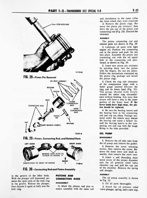
FIG. 28 Piston Pin Removal<br />
CONNECTING ROD<br />
OIL RING ASSEMBLY<br />
1119-B<br />
ASSEMBLY<br />
The piston, connecting rod and<br />
related parts are shown in Fig. 29.<br />
1. Lubricate all parts with light<br />
engine oil. Position the connecting<br />
rod in the piston and push the pin<br />
into place. Assemble the piston and<br />
connecting rod with the oil squirt<br />
hole in the connecting rod posi<br />
tioned as shown in Fig. 30.<br />
2. Insert new piston pin retainers<br />
by spiraling them<br />
into the piston<br />
with the fingers. Do not use pliers.<br />
Follow the instructions contained on<br />
the piston ring<br />
the piston rings.<br />
3. Check the ring<br />
package and install<br />
side clearance<br />
of the <strong>com</strong>pression rings with a<br />
feeler gauge inserted between the<br />
ring and its lower land (Fig. 31).<br />
The gauge should slide freely<br />
around the entire ring circumfer<br />
ence without binding. Any wear that<br />
occurs will form a step at the inner<br />
portion of the lower land. If the<br />
lower lands have high steps, the pis<br />
ton should be replaced.<br />
4. Be sure the bearing inserts and<br />
the bearing bore in the connecting<br />
NUT<br />
BEARING INSERTS<br />
RETAINER<br />
rod and cap<br />
are clean. Foreign ma<br />
terial under the inserts may distort<br />
the bearing and cause a failure. In<br />
stall the bearing inserts in the con<br />
necting rod and cap<br />
with the tangs<br />
fitting in the slots provided.<br />
1559-B<br />
FIG. 29 Piston, Connecting Rod, and Related Parts<br />
LEFT BANK RIGHT BANK<br />
OIL PUMP<br />
DISASSEMBLY<br />
1. Remove the oil inlet tube from<br />
the oil pump and remove the gasket.<br />
2. Remove the cover retaining<br />
screws, then remove the cover. Re<br />
BEARING LOCK SLOTS TO<br />
OUTSIDE OF ENGINE "V"<br />
INDENTATION TO FRONT OF ENGINE<br />
?<br />
FRONT<br />
I 11 20-A<br />
FIG. 30 Connecting Rod and Piston Assembly<br />
move the inner rotor and shaft as<br />
sembly, then remove the outer race.<br />
3. Insert a self<br />
threading sheet<br />
metal screw of the proper diameter<br />
into the oil pressure relief valve<br />
chamber cap and pull the cap out<br />
of the chamber. Remove the spring<br />
and plunger.<br />
in the groove of the lifter body.<br />
With the plunger still depressed, po<br />
sition the open ends of the lock ring<br />
in the groove. Release the plunger,<br />
then depress it again to fully<br />
seat the<br />
Jock ring.<br />
PISTONS AND<br />
CONNECTING RODS<br />
DISASSEMBLY<br />
1. Mark the pistons and pins to<br />
assure<br />
assembly<br />
with the same rod<br />
and<br />
ASSEMBLY<br />
The oil<br />
pump assembly is shown<br />
in Fig. 32.<br />
1. Oil all parts thoroughly.<br />
2. Install the oil pressure relief<br />
valve plunger, spring, and a new cap.


