

DEMO - 1959 Ford Thunderbird Shop Manual - ForelPublishing.com
DEMO - 1959 Ford Thunderbird Shop Manual - ForelPublishing.com
DEMO - 1959 Ford Thunderbird Shop Manual - ForelPublishing.com

Create successful ePaper yourself
Turn your PDF publications into a flip-book with our unique Google optimized e-Paper software.
on"<br />
1-23<br />
Section<br />
1-2<br />
THUNDERBIRD 352 SPECIAL<br />
Page<br />
1 Description 1-23<br />
2 Engine Removal and<br />
Installation 1-28<br />
3 Engine Disassembly (Engine<br />
Removed) 1-30<br />
4 Disassembly and Assembly<br />
of Component Parts 1-32<br />
Section<br />
V-8<br />
Page<br />
Valve Rocker Arm Shaft. 1-32<br />
Cylinder Heads 1-33<br />
Hydraulic Valve Lifters. . 1-34<br />
Pistons and Connecting<br />
Rods 1-35<br />
Oil Pump 1-35<br />
Section<br />
Page<br />
5 Engine Assembly (Engine<br />
Removed) 1-36<br />
6 Repair Operations (Engine<br />
Installed) 1-44<br />
Engine Supports 1-44<br />
Intake Manifold 1-45<br />
Cylinder Heads 1-45<br />
Crankshaft Damper 1-45<br />
Cylinder Front Cover and<br />
Timing Chain 1-45<br />
Camshaft 1-46<br />
Hydraulic Valve Lifter<br />
Replacement 1-46<br />
Flywheel 1-46<br />
Oil Filter Replacement. . . 1-47<br />
Oil Pan and Oil ...<br />
Pump 1-47<br />
DESCRIPTION<br />
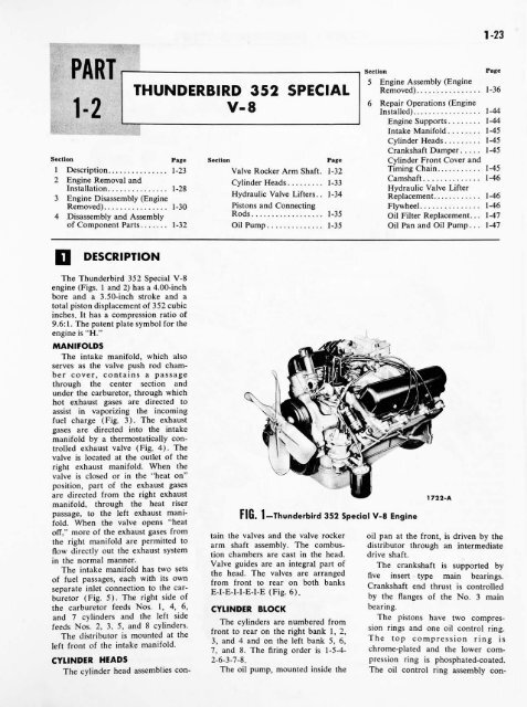
The <strong>Thunderbird</strong> 352 Special V-8<br />
engine (Figs. 1<br />
and 2) has a 4.00-inch<br />
bore and a 3.50-inch stroke and a<br />
total piston displacement of 352 cubic<br />
inches. It has a <strong>com</strong>pression ratio of<br />
9.6:1. The patent plate symbol for the<br />
engine is "H."<br />
MANIFOLDS<br />
The intake manifold, which also<br />
serves as the valve push rod cham<br />
ber cover, contains a passage<br />
through the center section and<br />
under the carburetor, through which<br />
hot exhaust gases are directed to<br />
assist in vaporizing the in<strong>com</strong>ing<br />
fuel charge (Fig. 3). The exhaust<br />
gases<br />
are directed into the intake<br />
manifold by<br />
a thermostatically con<br />
trolled exhaust valve (Fig. 4). The<br />
valve is located at the outlet of the<br />
right exhaust manifold. When the<br />
valve is closed or in the "heat<br />
position, part of the exhaust gases<br />
are directed from the right exhaust<br />
1722-A<br />
manifold, through the heat riser<br />
passage, to the left exhaust mani<br />
FIG. 1 <strong>Thunderbird</strong> 352 Special V-8 Engine<br />
fold. When the valve opens "heat<br />
off,"<br />
more of the exhaust gases from<br />
tain the valves and the valve rocker oil pan at the front, is driven<br />
the right manifold are permitted to<br />
by the<br />
arm shaft assembly. The <strong>com</strong>bus distributor through an intermediate<br />
flow directly<br />
out the exhaust system<br />
tion chambers are cast in the head. drive shaft.<br />
in the normal manner.<br />
Valve guides are an integral part of The crankshaft is supported<br />
The intake manifold has two sets<br />
by<br />
the head. The valves are arranged<br />
of fuel passages, each with its<br />
five insert<br />
own<br />
type main bearings.<br />
from front to rear on both banks<br />
separate inlet connection to the car<br />
Crankshaft end thrust is controlled<br />
E-I-E-I-I-E-I-E (Fig. 6).<br />
buretor (Fig. 5). The right side of<br />
by the flanges of the No. 3 main<br />
the carburetor feeds Nos. 1, 4, 6, CYLINDER BLOCK<br />
bearing.<br />
and 7 cylinders and the left side<br />
The pistons have two <strong>com</strong>pres<br />
The cylinders are numbered from<br />
feeds Nos. 2, 3, 5, and 8 cylinders.<br />
sion rings and one oil control ring.<br />
front to rear on the right bank<br />
The distributor is mounted at the<br />
1, 2,<br />
3, and 4 and on the left bank The<br />
5, 6, top <strong>com</strong>pression ring<br />
left front of the intake is<br />
manifold.<br />
7, and 8. The firing<br />
order is<br />
1-5-4- chrome-plated and the lower <strong>com</strong><br />
CYLINDER HEADS<br />
2-6-3-7-8.<br />
pression ring is phosphated-coated.<br />
The cylinder head assemblies con- The oil pump, mounted inside the<br />
The oil control ring assembly con-


