

DEMO - 1959 Ford Thunderbird Shop Manual - ForelPublishing.com
DEMO - 1959 Ford Thunderbird Shop Manual - ForelPublishing.com
DEMO - 1959 Ford Thunderbird Shop Manual - ForelPublishing.com

Create successful ePaper yourself
Turn your PDF publications into a flip-book with our unique Google optimized e-Paper software.
PART 1-2 -THUNDERBIRD 352 SPECIAL V-8 1-29<br />
ToolT53L300-A<br />
Tool1009<br />
ToolT58P-6000A<br />
1727-<br />
1728-A<br />
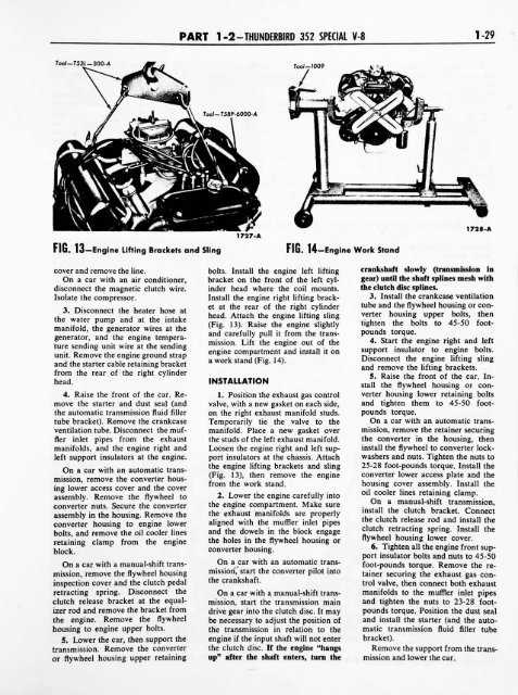
Fib. 13 Engine Lifting Brackets and Sling<br />
FIG. 14 Engine Work Stand<br />
cover and remove the line.<br />
On a car with an air conditioner,<br />
disconnect the magnetic clutch wire.<br />
Isolate the <strong>com</strong>pressor.<br />
3. Disconnect the heater hose at<br />
the water pump<br />
and at the intake<br />
manifold, the generator wires at the<br />
generator, and the engine tempera<br />
ture sending unit wire at the sending<br />
unit. Remove the engine ground strap<br />
and the starter cable retaining bracket<br />
from the rear of the right cylinder<br />
head.<br />
4. Raise the front of the car. Re<br />
move the starter and dust seal (and<br />
the automatic transmission fluid filler<br />
tube bracket). Remove the crankcase<br />
ventilation tube. Disconnect the muf<br />
fler inlet pipes from the exhaust<br />
manifolds, and the engine right and<br />
left support insulators at the engine.<br />
On a car with an automatic trans<br />
mission, remove the converter hous<br />
lower access cover and the cover<br />
ing<br />
assembly. Remove the flywheel to<br />
converter nuts. Secure the converter<br />
assembly in the housing. Remove the<br />
converter housing to engine lower<br />
bolts, and remove the oil cooler lines<br />
retaining clamp from the engine<br />
block.<br />
On a car with a manual-shift trans<br />
mission, remove the flywheel housing<br />
inspection cover and the clutch pedal<br />
retracting<br />
spring. Disconnect the<br />
clutch release bracket at the equal<br />
izer rod and remove the bracket from<br />
the engine. Remove the flywheel<br />
housing to engine upper bolts.<br />
5. Lower the car, then support the<br />
transmission. Remove the converter<br />
or flywheel housing upper retaining<br />
bolts. Install the engine left lifting<br />
bracket on the front of the left cyl<br />
inder head where the coil mounts.<br />
Install the engine right lifting brack<br />
et at the rear of the right cylinder<br />
head. Attach the engine lifting sling<br />
(Fig. 13). Raise the engine slightly<br />
and carefully pull it from the trans<br />
mission. Lift the engine out of the<br />
engine <strong>com</strong>partment and install it on<br />
a work stand (Fig. 14).<br />
INSTALLATION<br />
1. Position the exhaust gas control<br />
valve, with a new gasket on each side,<br />
on the right exhaust manifold studs.<br />
Temporarily tie the valve to the<br />
manifold. Place a new gasket over<br />
the studs of the left exhaust manifold.<br />
Loosen the engine right and left sup<br />
port insulators at the chassis. Attach<br />
the engine lifting brackets and sling<br />
(Fig. 13), then remove the engine<br />
from the work stand.<br />
2. Lower the engine carefully into<br />
the engine <strong>com</strong>partment. Make sure<br />
the exhaust manifolds are properly<br />
aligned with the muffler inlet pipes<br />
and the dowels in the block engage<br />
the holes in the flywheel housing or<br />
converter housing.<br />
On a car with an automatic trans<br />
the crankshaft.<br />
start the converter pilot into<br />
On a car with a manual-shift trans<br />
mission, start the transmission main<br />
drive gear into the clutch disc. It may<br />
be necessary to adjust the position of<br />
the transmission in relation to the<br />
engine if the input shaft will not enter<br />
the clutch disc. If the engine "hangs<br />
up"<br />
after the shaft enters, turn the<br />
crankshaft slowly<br />
(transmission in<br />
gear) until the shaft splines mesh with<br />
the clutch disc splines.<br />
3. Install the crankcase ventilation<br />
tube and the flywheel housing or con<br />
verter housing upper bolts, then<br />
tighten the bolts to 45-50 foot<br />
pounds torque.<br />
4. Start the engine right and left<br />
support insulator to engine bolts.<br />
Disconnect the engine lifting sling<br />
and remove the lifting brackets.<br />
5. Raise the front of the car. In<br />
stall the flywheel housing or con<br />
verter housing lower retaining bolts<br />
and tighten them to 45-50 foot<br />
pounds torque.<br />
On a car with an automatic trans<br />
mission, remove the retainer securing<br />
the converter in the housing, then<br />
install the flywheel to converter lock<br />
washers and nuts. Tighten the nuts to<br />
25-28 foot-pounds torque. Install the<br />
converter lower access plate and the<br />
housing<br />
cover assembly. Install the<br />
oil cooler lines retaining clamp.<br />
On a manual-shift transmission,<br />
install the clutch bracket. Connect<br />
the clutch release rod and install the<br />
clutch retracting<br />
spring. Install the<br />
flywheel housing lower cover.<br />
6. Tighten all the engine front sup<br />
port insulator bolts and nuts to 45-50<br />
foot-pounds torque. Remove the re<br />
tainer securing the exhaust gas con<br />
trol valve, then connect both exhaust<br />
manifolds to the muffler inlet pipes<br />
and tighten the nuts to 23-28 foot<br />
pounds torque. Position the dust seal<br />
and install the starter (and the auto<br />
matic transmission fluid filler tube<br />
bracket).<br />
Remove the support from the trans<br />
mission and lower the car.


