
Create successful ePaper yourself
Turn your PDF publications into a flip-book with our unique Google optimized e-Paper software.
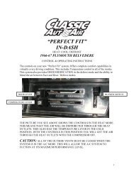
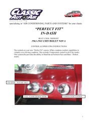
specializing in “AIR CONDITIONING, PARTS AND SYSTEMS” for your classic<br />
vehicle<br />
“PERFECT FIT SERIES”<br />
IN-DASH<br />
HEAT/ COOL/ DEFROST<br />
1965-66 MUSTANG<br />
CONTROL & OPERATING INSTRUCTIONS<br />
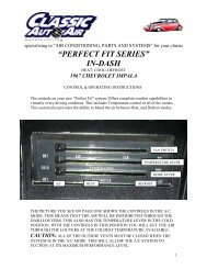
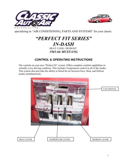
The controls on your new “Perfect Fit” system. Offers complete comfort capabilities in<br />
virtually every driving condition. This includes Temperature control in all of the modes.<br />
This system also provides the ability to blend the air between Face, Heat, and Defrost<br />
modes simultaneously.<br />
FAN SWITCH<br />
HEAT LEVER TEMPERTURE LEVER DEFROST LEVER<br />
1
THE PICTURE YOU SEE ABOVE SHOWS THE CONTROLS IN THE FACE MODE.<br />
THIS MEANS THAT ALL OF THE AIR WILL BE DISTRIBUTED THROUGH THE<br />
DASH LOUVERS. THIS ALSO HAS THE TEMPERATURE LEVER IN THE COLD<br />
POSITION. WITH THE CONTROLS IN THIS POSITION YOU WILL GET THE AIR<br />
THROUGH THE DASH LOUVERS AT ROOM TEMPERATURE.<br />
CAUTION: ALL OF THE OUTSIDE VENTS MUST BE CLOSED WHEN THE<br />
SYSTEM IS IN THE A/C MODE. THIS WILL ALLOW THE A/C SYSTEM TO<br />
FUCTION AT ITS MAXIMUM PERFORMANCE LEVEL.<br />
THE FOLLOWING SUMMARY WILL DESCRIBE EACH OF THE CONTROL<br />
LEVERS FUNCTION.<br />
FAN SPEED SWITCH: There are 3 speeds plus Off. When the switch is in the off<br />
position it will disconnect the 12V power to the Blower Motor and the A/C Clutch. This<br />
will shut down the entire system. When the switch is moved to any of the blower speeds<br />
1,2 or 3 there is 12V supplied to the Micro-Switch which is mounted on the defrost air<br />
housing.<br />
HEAT MODE: When the heat lever is pushed down, it will allow the air to go between<br />
the floor ducts and the face louvers. Only when the lever is in the lowest position will all<br />
of the air stop coming out of the face louvers and blow on the floor.<br />
TEMPERATURE CONTROL: The temperature lever as shown is in the COLDEST<br />
temperature position. As the lever is pushed down the temperature of the discharged air<br />
will rise to the HOTTEST point which is the lowest position of the lever.<br />
Note: The temperature lever will function in any of the modes.<br />
DEFROST MODE: This system allows for Dehumidification of the air in the Defrost<br />
mode. The Heat lever must be in the down position. The lever marked DEF. must be at the<br />
bottom position in order to get the maximum air flow to the windshield and to trip the<br />
Micro-Switch. This will activate the Compressor Clutch.<br />
AIR CONDITIONING MODE: The picture shows the controls in the Face Mode<br />
(air-flow out the dash louvers).<br />
When <strong>Air</strong> Conditioning is required the compressor clutch must be activated. This is<br />
accomplished by pushing the Def. lever all the way to the bottom. When the compressor is<br />
activated the Temperature Lever will control the air from maximum cold through<br />
maximum heat.<br />
2
specializing in “AIR CONDITIONING, PARTS AND SYSTEMS” for your classic<br />
vehicle<br />
INSTALLATION INSTRUCTIONS<br />
1965-66 MUSTANG<br />
Congratulations! ! You have just purchased the highest quality, best performing A/C system ever<br />
designed for you <strong>Classic</strong> Car. To obtain the high level of performance and dependability our systems<br />
are known for, pay close attention to the following instructions.<br />
Before beginning the installation check the box for the correct components.<br />
Evaporator<br />
Face Duct Assembly<br />
Defrost / Heat Duct Assembly<br />
Inlet <strong>Air</strong> Block Off Assembly<br />
Firewall Block Off Assembly<br />
Flex Hose 2”dia. (3) 2’, (1) 3’<br />
Flex Hose 2 ½”dia. (1) 1’, (1) 2’, (1) 3’<br />
Sack Kit Hardware<br />
Sack Kit Control<br />
IMPORTANT INFORMATION<br />
1. Before starting, read the instructions carefully and follow proper sequence.<br />
2. Check condition of engine mounts. Excessive engine movement can damage<br />
hoses to A/C, heater, radiator, transcooler, and power steering systems.<br />
3. Before starting, check vehicle interior electrical functions. i.e. interior lights,<br />
radio, horn, etc. When ready to start installation, disconnect battery.<br />
4. Fittings. Use one or two drops of lubricant on O’rings, threads and rear of bump<br />
for O’ring where female nut rides. Do not use thread tape or sealants.<br />
5. Always use two wrenches to tighten fittings. Try holding in one hand while<br />
squeezing together while other hand holds fitting in position.<br />
6. Shaft seals in a small percentage of compressors will require as much as 3-4<br />
hours run time to become leak free.<br />
7. Compressors supplied in our complete systems are filled with proper amount of<br />
oil.<br />
8. Compressor requires technician to hand turn 15-20 revolutions before and after<br />
charging with liquid from a charging station before running system.<br />
Compressors with damaged reed valves cannot be warranted.<br />
9. Should you have any technical questions, or are suspect of missing, or defective<br />
parts, call us immediately. Our knowledgeable staff will be glad to assist you.<br />
YOU CAN NOW BEGIN THE INSTALLATION<br />
3
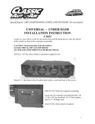
Remove Glove box,<br />
Ashtray, and Radio, set<br />
aside for reinstall.<br />
Note: If vehicle is<br />
equipped with a<br />
console, remove and<br />
retain.<br />
The removal of the Original Heater Assembly can be<br />
accomplished by disconnecting three control cables.<br />
One attached to the Heat/Defrost door.<br />
One attached to the Temperature door as<br />
shown.<br />
And one attached to the Vent / Heat door.<br />
Disconnect electrical harness.<br />
Also remove<br />
attachment screw<br />
located in front of<br />
air inlet.<br />
4
Locate blower motor on the firewall (Passenger<br />
Side) in the engine compartment. Remove 4 nuts<br />
around blower. Also disconnect electrical connector<br />
from the blower motor.<br />
Cut wires at grommet in firewall.<br />
DRAIN COOLANT FROM RADIATOR.<br />
Cut Heater hoses approximately 1” from firewall.<br />
Located on top of instrument panel is the radio<br />
speaker cover plate, carefully remove the screws and<br />
retain. Under the cover there are (2) defrost adaptors.<br />
Remove and discard adaptors and the defrost flex<br />
duct that is attached.<br />
Remove complete Heater Assembly and defrost flex<br />
ducting. Discard.<br />
On the back side of the control head there are<br />
(2) nuts and retaining clips. Remove and retain.<br />
Remove the control head assembly.<br />
NUT & CLIP<br />
5
Using an allen wrench carefully remove blower<br />
switch knob and retain. Remove the control cables<br />
and the original blower switch and discard. Set the<br />
control head aside for modification and reinstall.<br />
NOTE: RETAIN ALL OF THE ORIGINAL<br />
HARDWARE.<br />
NOTE: When removing the control cables<br />
retain the original screws and cable brackets.<br />
Retain screws and brackets<br />
Locate original wiring harness that supplied power<br />
to the original heater motor. These wires were<br />
previously cut on the engine side of the firewall.<br />
Behind glove box opening pull these wires out of<br />
their grommet. Measure 4” from harness cut both<br />
wires. On the black wire attach a ¼” insulated<br />
male spade connector.<br />
6
1 3/8<br />
Locate bottom left mounting hole in the<br />
firewall that attached the original heater motor.<br />
From inside of the vehicle drill a 5/8 dia. hole<br />
for the drain tube. This is located as shown or<br />
find template located on page 19.<br />
5/8 FROM<br />
CENTER OF<br />
HOLE<br />
Caution: On the engine side of the firewall there is a brake line.<br />
Do not drill through. It may be necessary to carefully relocate<br />
this line.<br />
All modifications to the vehicle are complete. You can now begin<br />
installing your <strong>Classic</strong> <strong>Air</strong> “Perfect Fit Series” System.<br />
7
Locate <strong>Air</strong> Inlet Block off Assembly. Install<br />
over hole in inlet cowl as shown. Attach with<br />
(2) #10 x ¾ Tek screws.<br />
Locate the mounting location as shown and<br />
attach the ¼-20 J-clip supplied.<br />
Locate defrost / heat duct assembly and<br />
attach to the evaporator using (2) #10 x 5/8<br />
pan head philips screws.<br />
NOTE: Be sure that the s-clips are pushed<br />
over flange on evaporator.<br />
Install the Evaporator in vehicle.<br />
#10 x 5/8 Screws<br />
8
On back side of the unit next to the firewall<br />
is a mounting bracket with a ¼-20 j-clip. On<br />
the engine side of the firewall attach with one<br />
¼-20 x 5/8 screw and ¼” SAE washer.<br />
This location is the bottom right hole that<br />
attached the original heater assembly.<br />
The second ¼-20 x 5/8 screw attaches the blower<br />
motor mounting bracket in the same location as<br />
the original heater mounting in front of the <strong>Air</strong><br />
Inlet. The blower support bracket will have an<br />
additional hole behind the ¼-20 screw. Install a<br />
#10x3/4 Tek screw supplied, through this hole and<br />
into the cowling.<br />
Locate in the Hardware Sack Kit the UPPER<br />
MOUNTING BRACKET and attach to evaporator<br />
using (2) #10 x 5/8 pan head philips screws.<br />
Attach other end to the cowling. Attach<br />
with #10 x ¾ Tek screw supplied.<br />
NOTE: BE SURE TO HOLD UNIT LEVEL<br />
WITH BOTTOM OF INSTRUMENT PANEL.<br />
TO ALLOW PROPER DRAIN OF<br />
CONDENSATION.<br />
#10 x ¾ Tek screw<br />
9
Locate in the hardware sack kit the Firewall<br />
Block Off Assembly. Install over the hose connections<br />
in the engine compartment. Attach with (2) #10 x ¾<br />
Tek screws.<br />
Seal around the tubes with refrigerant tape.<br />
Locate in the engine compartment the heater hose<br />
hookups and the refrigerant connections. It is<br />
recommended that you replace the heater hose from<br />
the engine to the tube hookups.<br />
The supply line from the engine will be attached to<br />
lower heater connection as shown. Cut 6” of hose off<br />
the return line. Use this and attach to the upper heater<br />
connection along with the Water valve and #10 worm<br />
gear clamps supplied in kit. Attach the return line to<br />
the end of the water valve.<br />
See Technical Data Sheet located on page 18.<br />
Locate in the Hardware Sack Kit a 6”<br />
piece of ½” dia. clear Drain tube. Insert<br />
this through the 5/8 dia hole previously<br />
drilled and attach over the drain nipple as<br />
shown. Seal around tube with refrigerant<br />
tape.<br />
Engine compartment components should be installed at this<br />
time. Carefully follow the electrical hookup instructions<br />
provided on page 17.<br />
10
Locate Control Head that was previously removed.<br />
Locate Control Switch Mounting Bracket, and the<br />
Blower Switch in the Control Sack Kit. Attach<br />
bracket to the control head with original screw. Turn<br />
controls over and install (1) #8 x 3/8 pan head<br />
philips screw through control head and into switch<br />
bracket. Attach switch to the bracket using (2) #6 x<br />
3/8 pan head screws. Attach original Switch Knob<br />
using allen wrench.<br />
#8 x 3/8 Screw<br />
Original screw<br />
Attach (3) control cables to the<br />
control head utilizing the Cable<br />
Mounting Brackets and original<br />
screws and cable clamps as shown.<br />
The longest cable goes in the<br />
MIDDLE the shortest cable to the<br />
RIGHT and the last one goes on the<br />
LEFT. (See picture). The cable<br />
housing should be flush with the<br />
mounting point.<br />
LEFT<br />
MIDDLE<br />
RIGHT<br />
11
Also attach Wire Harness Assembly to the<br />
Blower Switch.<br />
Reference: The Electrical Diagram on the last<br />
page for correct connector location.<br />
Install Control Assembly through opening in<br />
the Instrument Panel reattach using original<br />
nuts and retaining clips. Route the cables and<br />
electrical harness as shown below.<br />
Hook up the electrical connections per<br />
Electrical Diagram.<br />
Original clip and nut.<br />
Route cable attached to the Heat<br />
lever and attach to the Face/ Heat<br />
door, located on the Evaporator.<br />
NOTE: Insert cable wire into<br />
fourth hole from the end of crank<br />
arm<br />
Use #10 x 5/8 pan head screw.<br />
Route electrical harness straight<br />
back from the contols and around<br />
behind defrost duct adaptors, and<br />
accross top of the unit.<br />
Hook up electricals to blower motor , resistor<br />
and attach ground wire to the vehicle body.<br />
Refer to electrical diagram on page 15.<br />
Route compressor clutch wire through<br />
remaining hole in the Fire wall block off<br />
assembly.<br />
#10 X 5/8 SCREW<br />
CAUTION: BE SURE THAT WIRE HARNESS DOES NOT INTERFER WITH THE<br />
OPERATION OF CONTROLS.<br />
12
The cable attached to the defrost control<br />
lever should be routed and connected to the<br />
defrost duct assembly.<br />
NOTE: Insert cable wire into second hole<br />
from the end of the crank arm.<br />
Use #10 x 5/8 pan head screw<br />
INSTALL (2) 1” dia. CAP PLUGS OVER<br />
HOLES. SLOT ONE FOR THE CABLE.<br />
Route cable attached to the temp lever along the<br />
firewall and out through upper hole that was used by<br />
the original heater hose. Attach cable in the engine<br />
compartment to the water valve.<br />
NOTE: When Temperature lever is at the top position<br />
water valve should be closed.<br />
CAUTION: The control cables are equipped with inline adjusters. Adjust the<br />
Defrost, Face / Heat door, and Water valve cable so that full travel of the Control<br />
lever, operates the door to its full travel. Make sure that the water valve completely<br />
closes when the Lever is in the cold position.<br />
The Micro Switch that is mounted on Defrost / heat door is used to turn on<br />
compressor clutch. This will occur when control lever is in the defrost position. It<br />
may be necessary to adjust thin metal arm on the switch. Make sure that the Clutch<br />
Micro Switch is depressed when lever is in the defrost position. This will provide<br />
dehumidification of the air, resulting in a faster clearing of the windshield.<br />
It is recommended that the Radio be reinstalled at this time.<br />
13
Following steps are for left and right Defrost<br />
Diffusers<br />
Locate 2” dia. Flex Hose (2) pieces 2’ long<br />
Also locate from the Hardware sack kit (2)<br />
2” x 2 ½ adaptors, and (2) Defrost adaptors.<br />
Install Defrost adaptors through the<br />
instrument panel and secure with clips<br />
supplied. Attach 2’ flex hose to the 2” x 2<br />
½” adaptors using (2) #10 x 5/8 pan head<br />
philips screw. Push on Adaptors as shown<br />
below. The other end of the flex hose is<br />
installed over the defrost outlets on unit.<br />
2’<br />
2’<br />
2” x 2 ½ Adaptor<br />
2’ Long x 2” dia. Flex Hose<br />
Defrost Adaptors (2)<br />
Reinstall radio speaker cover plate over the defrost outlets using the<br />
original screws.<br />
Install the face duct assembly. Make sure that the s-clips<br />
are pushed over outlet flange. Attach using (2) #10 x<br />
5/8” pan head screws.<br />
#10 x 5/8” Screws<br />
14
Locate drivers side Ball Louver Assembly, and one of the two slim line louvers.<br />
Attach to bottom edge of Instrument Panel as shown below.<br />
Use (2) #10 x 5/8 pan head screws through top of the ball louver assembly, and (1)<br />
#10 x 5/8 pan head Philips screw into the kick panel.<br />
Use (2) #10 x 5/8 pan head Philips screws through slim line louver and into the<br />
instrument panel.<br />
Locate 2” dia. flex hose 2’ piece and route as shown below.<br />
Ball Louver Assembly<br />
Slim Line Louver<br />
2” dia. x 2’ flex hose. Attach to the lower hose adaptor.<br />
Locate 2 ½” dia. flex hose provided.<br />
Find 1’ piece and install from slim<br />
line louver to the upper hose<br />
adaptor on the face duct assembly.<br />
15
Locate the passenger side Ball Louver Assembly, and the last Slim Line Louver.<br />
Use (2) #10 x 5/8 pan head screws through the top of ball louver assembly, and (1)<br />
#10 x 5/8 pan head Philips screw into kick panel.<br />
Use (2) #10 x 5/8 pan head Philips screws through the slim line louver and into<br />
instrument panel.<br />
Slim Line Louver<br />
Ball Louver Assembly<br />
The remaining 2 ½” dia flex hose in (1) piece 3’ long<br />
and (1) piece 2’ long.<br />
Attach 2’ piece to the face duct on left front outlet<br />
adaptor. This will then be routed down to the<br />
slimline louver as shown.<br />
The 3’ piece will be routed from the remaining face<br />
duct adaptor over defrost duct hose and across to<br />
passenger ball louver assembly.<br />
15” flex hose 28” flex hose<br />
16
Locate new glove box provided in kit.<br />
Install using original hardware.<br />
Caution: Carefully check under the Instrument Panel for all cables, electrical<br />
harness, or Flex Hose that might interfere with the safe operation of the vehicle.<br />
Make sure that you cycle the Windshield Wipers to insure proper clearance of<br />
mechanism.<br />
Reinstall the Glove box door, and Ashtray.<br />
17
If vehicle is equipped with center<br />
console, Modify as shown and<br />
reinstall.<br />
REMOVE<br />
ENGINE COMPARTMENT<br />
Locate in the Condenser kit the Drier, Drier Mounting bracket, pressure switch kit,<br />
Liquid Tube, (2) #10 tek screws, and (2) #6 o-rings.<br />
To locate the drier use the<br />
liquid tube from firewall to<br />
the spring tower as shown.<br />
Attach using (2) #10x ¾”<br />
tek screws.<br />
Install tube using the (2) #6<br />
o-rings and few drops of<br />
mineral oil.<br />
TOWER SUPPORT BRACE<br />
SPRING<br />
TOWER<br />
(2) #10<br />
TEK<br />
SCREWS<br />
Attach the pressure switch to the top of the drier using a<br />
few drops of mineral oil.<br />
INSTALL COMPRESSOR AND MOUNTING HARDWARE USING INSTRUCTIONS<br />
SUPPLIED WITH KIT. BE SURE THAT COMPRESSOR ON V8 ENGINE IS<br />
INSTALLED WITH FITTINGS 90 Deg. FACING DRIVERS SIDE FENDER<br />
18
Remove the following components: Center Hood Latch Assembly, Grille assembly, and<br />
(2) horns. Set hardware and parts aside for reinstallation.<br />
Locate the Condenser Coil, and liquid tube assembly. Attach tube to the coil as shown<br />
using (1) #6 o-ring and a few drops of mineral oil.<br />
Locate (2) top and (2) lower condenser mounting brackets, and (8) #10 x 3/8”<br />
HWH screws.<br />
Attach top brackets to condenser as shown.<br />
Attach lower brackets to the bottom of condenser at the top of the slots.<br />
19
Locate the tube support bracket,<br />
tube clamp, (1) #10 u-clip, and (2)<br />
#10 x 3/8 hex head screws.<br />
Attach to the condenser as shown.<br />
TUBE SUPPORT BRACKET<br />
TOP EDGE OF RADIATOR SUPPORT<br />
ORIGINAL HORN MOUNTING<br />
Locate drill template on the<br />
last page of the instructions.<br />
Tape to the radiator support<br />
locate the (3) 3/16” dia holes.<br />
Carefully drill at locations<br />
shown on template.<br />
DO NOT ENLARGE THIS HOLE<br />
After drilling the (3) 3/16 dia holes.<br />
ENLARGE THESE (2) HOLES TO 1 3/8” DIA<br />
Using a 1 3/8” dia. hole saw enlarge the<br />
(2) bottom holes.<br />
NOTE: THE LEFT HOLE IS CENTERED<br />
ON THE EDGE OF SUPPORT<br />
Slide Condenser Assembly into place as shown. The<br />
upper right attachment bracket should attach to the<br />
3/16 hole in radiator support. Attach using (1)<br />
#14 x ¾” tek washer head screw.<br />
Attach the top left bracket to the radiator support<br />
using the last #14 x ¾” tek washer head screw.<br />
20
Locate (2)<br />
# 10x ¾”<br />
tek screws.<br />
Attach lower<br />
mounting brackets<br />
To lower radiator<br />
support as shown<br />
Locate the Discharge hose, Liquid<br />
hose, (1) #8 o-ring, and (1) #6 o-<br />
ring.<br />
Attach the discharge hose to the<br />
condenser using the #8 o-ring and<br />
few drops of mineral oil. Tighten<br />
securely.<br />
Attach the liquid hose to the<br />
condenser using the #6 o-ring and<br />
a few drops of mineral oil.<br />
Tighten securely.<br />
Reinstall the Center Hood Latch Assembly, Grille assembly, and (2) horns. Using<br />
original hardware.<br />
21
The Liquid Hose that was attached to the condenser will<br />
route under the spring support brace and over to the drier<br />
mounted on the spring tower. Attach using (1) #6 o-ring and<br />
a few drops of mineral oil. Tighten fitting.<br />
VEHICLES WITH V8 ENGINES:<br />
Attach the disharge hose assembly that comes from the<br />
condenser to compressor.<br />
Attach using (1) #8 o-ring using a few drops of<br />
mineral oil.<br />
Locate the Suction Hose. The hose has (2) 90<br />
Degree fittings pre-attached in the correct position.<br />
One of the ends has a service fitting, This should be<br />
attached to the compressor.<br />
Connector to clutch<br />
22
The other end will attach to the suction tube coming<br />
from the evaporator assembly. Check for o-rings and<br />
apply oil before attachment.<br />
Tighten all fittings.<br />
Suction hose<br />
Locate female bullet connector that is supplied<br />
with the Hi-Low pressure switch.<br />
Cut one of the white wires from the pressure<br />
switch. Attach bullet connector to this wire<br />
and plug into the compressor clutch wire.<br />
Carefully route liquid<br />
and suction hoses<br />
As shown route the long white wire from the<br />
pressure switch along the suction hose and<br />
connect to the clutch wire. The other wire<br />
connects to the blue wire that was inserted<br />
through firewall.<br />
Ty-rap suction and liquid hose to the spring<br />
tower support.<br />
VEHICLES WITH 6 CYL. ENGINES.<br />
Attach the disharge hose assembly<br />
that is attached to condenser to the<br />
compressor.<br />
Attach using (1) #8 o-ring using a few<br />
drops of mineral oil.<br />
23
Locate the Suction Hose. Attach hose with 90<br />
Degree fitting with service port to the<br />
compressor.<br />
The other end will attach to the<br />
firewall. Use (2) #10 o-rings and a<br />
few drops of mineral oil.<br />
Ty-rap liquid hose to the spring tower support.<br />
24
CONDENSER INSTRUCTIONS<br />
1965 FORD RANCHERO WITH MUSTANG RADIATOR<br />
Remove hood latch assembly and grill and retain mounting hardware.<br />
Using templet for 1965 Ranchero cut holes in radiator cowl before installation of<br />
condenser assembly. NOTE: The voltage regulator will need to be relocated before<br />
cutting holes in the cowl.<br />
Attach upper condenser mounting brackets, and attach bottom brackets loosely as shown<br />
using (6) #10 x3/8” screws. Attach liquid tube to bottom of condenser using (1) o-ring<br />
and a few drops of mineral oil and tighten fitting. Attach support bracket and #6 clamp<br />
using (1) #10 u-clip and (2) #10 x 3/8” screws.<br />
25
TOP RIGHT MOUNTING HOLE<br />
Install condenser in front of<br />
radiator cowl as shown.<br />
Attaching top right bracket to<br />
hole previously drilled using<br />
(1) #14 x ¾” Tek screw, and<br />
align condenser and attach<br />
left side using (1) #14 tek<br />
screw.<br />
Attach the bottom brackets to lower<br />
radiator cowl as shown using (2) #10<br />
Tek screws, and tighten screws on<br />
condenser.<br />
Attach liquid hose to condenser using (1) #6<br />
o-ring and a few drops of mineral oil.<br />
Attach the #8 discharge hose to the condenser<br />
using (1) #8 o-ring and a few drops of mineral<br />
oil.<br />
Attach drier to drivers shock tower using (1)<br />
drier clamp and (2) #10x3/4” tek screws.<br />
Route #6 liquid hose from condenser to drier<br />
and attach using (1) #6 o-ring and a few drops<br />
of mineral oil. Tighten both ends of hose.<br />
26
Attach the other end of #8 discharge hose w/ service port to the compressor using (1) #8<br />
o-ring and a few drops of mineral oil. Tighten both ends of hose.<br />
Attach the #10 Suction Hose with the 90<br />
Deg. Fitting w/ service port to the<br />
compressor using (1) #10 o-ring and a few<br />
drops of mineral oil, and route the other end<br />
along firewall to evaporator, and attach using<br />
(1) #10 o-ring and a few drops of mineral oil<br />
and tighten both ends.<br />
Connector to clutch<br />
Attach liquid line to drier using (1) o-<br />
ring and a few drops of mineral oil,<br />
route hose along firewall as shown<br />
below. Attach the other end to the evaporator using (1) o-ring and a few drops of mineral<br />
oil, and tighten both ends. Tyrap both the suction and liquid hoses to the cross members<br />
as shown below. Route white wire from pressure switch and attach to compressor, and<br />
route the other white wire along suction hose and attach to the blue wire routed through<br />
firewall by evaporator. Tyrap wires to one of the hoses.<br />
TYRAPS<br />
LIQUID HOSE<br />
SUCTION HOSE<br />
27
THE ENGINE COMPARTMENT OF YOUR SYSTEM IS COMPLETE.<br />
THE UNIT IS READY FOR EVACUATION AND CHARGING.<br />
THIS SHOULD BE DONE BY A QUALIFIED AND CERTIFIED AIR<br />
CONDITIONING TECHNICIAN.<br />
NOTE: COMPRESSOR IS SUPPLIED WITH THE<br />
CORRECT OIL CHARGE. DO NOT ADD OIL TO SYSTEM.<br />
134a SYSTEMS<br />
24 oz OF REFRIGERANT<br />
Recommend that power fuse is 25 amp minimum<br />
Congratulations you have completed the install of your<br />
CLASSIC AUTO AIR climate control system.<br />
28
IMPORTANT<br />
CAUTION: WATER VALVE MUST BE INSTALLED PER<br />
THE INSTRUCTIONS.<br />
<strong>Classic</strong> <strong>Auto</strong> <strong>Air</strong> has done extensive testing on the correct method to install the water valve in order to get a<br />
repeatable and progressive temperature control.<br />
Locate the bottom connection from the evaporator/heater unit off of the firewall and attach a 6” piece of<br />
5/8” dia. heater hose with the supplied hose clamp. Next attach the inlet side of the water valve using<br />
another supplied hose clamp, (make sure the arrow on the water valve points toward the engine) Attach a<br />
heater hose from the outlet side of the water valve and route to the connection on the water pump.<br />
NOTE: WATER VALVE = WATER PUMP<br />
FROM HEATER CORE<br />
TO WATER PUMP<br />
COOLANT FLOW<br />
CAUTION: WATER VALVE MUST BE INSTALLED ON HEATER LINE ROUTED TO<br />
WATER PUMP.<br />
NOTE: COMPRESSOR PURCHASED WITH KIT IS<br />
SUPPLIED WITH THE CORRECT OIL CHARGE. DO NOT<br />
ADD OIL TO SYSTEM.<br />
134A SYSTEMS 24 oz OF REFRIGERANT<br />
Recommend that power fuse is 25amp minimum<br />
29
1-1025<br />
34