optical interference filters - SPOT Imaging Solutions
optical interference filters - SPOT Imaging Solutions
optical interference filters - SPOT Imaging Solutions

Create successful ePaper yourself
Turn your PDF publications into a flip-book with our unique Google optimized e-Paper software.
FISH and<br />
M-FISH <strong>Imaging</strong><br />
Application Note<br />
Interference Filters<br />
and Fluorescence <strong>Imaging</strong><br />
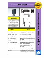
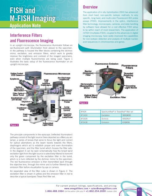
In an upright microscope, the fluorescence illuminator follows an<br />
epi-fluorescent path (illumination from above) to the specimen.<br />
In the pathway is housed the filter blocks containing the dichroic<br />
mirror, excitation, and emission <strong>filters</strong>, which work to greatly<br />
improve the brightness and contrast of the imaged specimens,<br />
even when multiple fluorochromes are being used. Figure 1<br />
illustrates the basic setup of the fluorescence illuminator on an<br />
upright microscope.<br />
Overview<br />
The application of in situ hybridization (ISH) has advanced<br />
from short lived, non-specific isotopic methods, to very<br />
specific, long lived, and multi-color Fluorescent-ISH probe<br />
assays (FISH). Improvements in the optics, <strong>interference</strong><br />
filter technology, microscopes, cameras, and data handling<br />
by software have allowed for a cost effective FISH setup<br />
to be within reach of most researchers. The application of<br />
mFISH (multiplex-FISH), coupled to the advances in digital<br />
imaging microscopy, have vastly improved the capabilities<br />
for non-isotopic detection and analysis of multiple nucleic<br />
acid sequences in chromosomes and genes.<br />
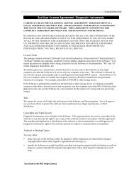
Figure 2<br />
Figure 1<br />
XF424<br />
SpectrumRed ® or TexasRed ® filter set<br />
XF1424 Excitation 580QM30<br />
XF2029 Dichroic 595DRLP<br />
XF3418 Emission 63QM36<br />
The principle components in the episcopic (reflected illumination)<br />
pathway consist of the light source (here depicted as a Mercury arc<br />
lamp), a series of lenses that serve to focus the light and correct<br />
for <strong>optical</strong> aberrations as the beam travels towards the <strong>filters</strong>,<br />
diaphragms which act to establish proper and even illumination<br />
of the specimen, and the filter turret which houses the filter sets.<br />
In the diagram it can be seen schematically how the broad band<br />
excitation light from the light source is selectively filtered to transmit<br />
only the green component by the excitation filter in the turret,<br />
which is in turn reflected by the dichroic mirror to the specimen.<br />
The red fluorescence emission is then transmitted back through<br />
the objective lens, through the mirror and is further filtered by the<br />
emission filter before visualization by eye or camera.<br />
An expanded view of the filter cube is shown in Figure 2. The<br />
excitation filter is shown in yellow and the emission filter in red to<br />
describe a typical bandpass Texas Red filter set.<br />
For current product listings, specifications, and pricing:<br />
www.omega<strong>filters</strong>.com • sales@omega<strong>filters</strong>.com<br />
1.866.488.1064 (toll free within USA only) • +1.802.254.2690 (outside USA)<br />
81