optical interference filters - SPOT Imaging Solutions
optical interference filters - SPOT Imaging Solutions
optical interference filters - SPOT Imaging Solutions

Create successful ePaper yourself
Turn your PDF publications into a flip-book with our unique Google optimized e-Paper software.
middle and bottom left images. Bottom right panel is an overlaid<br />
pseudo-colored image of the series. In order to minimize the<br />
Figure 6<br />
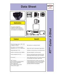
By incorporating the design strategy of narrow band, steep-edged<br />
<strong>filters</strong>, the spectral window for adding multiple fluorescent probes<br />
widens without the cost of adding emission bleed-though between<br />
fluorophores.<br />
Figure 8<br />
Transmission (%)<br />
100<br />
90<br />
80<br />
70<br />
60<br />
50<br />
40<br />
30<br />
20<br />
10<br />
0<br />
FITC and Cy3: Narrow band mFISH set for FITC<br />
400 500 600<br />
Wavelength (nm)<br />
XF1406 Excitation Filter<br />
XF3415 Emission Filter<br />
FITC Excitation<br />
FITC Emission<br />
Cy 3 Excitation<br />
Cy3 Emission<br />
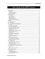
spectral bleed-through of very closely spaced fluorophores in<br />
multicolor labeling schemes, specialized narrow band filter sets<br />
are needed. Exciter <strong>filters</strong> of 10-20nm in bandwidth and emission<br />
<strong>filters</strong> of 20-40nm provided the specificity necessary to achieve the<br />
degree of sensitivity and spectral resolution required in mFISH.<br />
Figure 7 shows a typical wide band FITC filter set overlaid on the<br />
excitation and emission peaks of FITC and CY 3.<br />
Figure 7<br />
Transmission (%)<br />
100<br />
90<br />
80<br />
70<br />
60<br />
50<br />
40<br />
30<br />
20<br />
10<br />
0<br />
(Image courtesy of Octavian Henegariu, Yale University)<br />
400 450 500 550 600 650<br />
Wavelength (nm)<br />
XF404 Excitation Filter<br />
XF404 Emission Filter<br />
FITC Excitation<br />
FITC Emission<br />
Cy 3 Excitation<br />
Cy3 Emission<br />
Although the <strong>filters</strong> are designed for covering a substantial area<br />
under the absorption and emission curves, there is a significant<br />
overlap with both the excitation and emission curves of Cy3, thus<br />
resulting in FITC channel contamination by Cy3. A solution is<br />
seen in Figure 8, where excitation and emission bands have been<br />
narrowed to improve the spectral resolution of FITC from Cy3,<br />
especially in the emission band. By limiting the red edge of the<br />
emission filter a reduction in the area under the emission curve of<br />
the Cy3 dye of about 4-fold is achieved.<br />
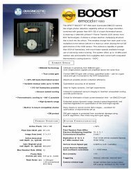
This can be seen in Figure 9 where three fluorophores are effectively<br />
separated within a spectral window of less than 300 nm. A fourth<br />
fluorophore such as Cy 3.5 could easily be incorporated in this<br />
scheme, as well in the 570-620nm region, but is omitted to reduce<br />
congestion.<br />
Figure 9<br />
Transmission (%)<br />
100<br />
90<br />
80<br />
70<br />
60<br />
50<br />
40<br />
30<br />
20<br />
10<br />
0<br />
425 475 525 575 625 675 725<br />
Wavelength (nm)<br />
XF1406 Excitation Filter<br />
XF3415 Emission Filter<br />
Cy3 Excitation Filter<br />
Cy3 Emission Filter<br />
CY 5 Excitation Filter<br />
Cy 5 Emission Filter<br />
FITC Excitation<br />
FITC Emission<br />
Cy 3 Excitation<br />
Cy3 Emission<br />
Cy5 Excitation<br />
Cy5 Emission<br />
The demands on the <strong>interference</strong> <strong>filters</strong> required for mFISH are<br />
such that it is necessary to provide a specific category of products<br />
which are matched together to make optimal use of the available<br />
bandwidth for each mFISH fluorophore. Product table on pages<br />
Page 1<br />
79-80 shows the Omega Optical series of filter sets for the more<br />
prevalent fluorophores used in mFISH, along with excitation and<br />
emission filter bandwidths. Note: all are single fluorophore filter<br />
sets with the exception of and XF467-1 which use single excitation<br />
<strong>filters</strong> for each fluorophore and triple band dichroics and emission<br />
<strong>filters</strong>. This setup minimizes registration shift and stage movement<br />
by requiring only that an external filter slider or wheel be moved<br />
to excite the different dyes while the multi-band dichroics and<br />
emission <strong>filters</strong> are kept stationary in the microscope turret.<br />
For current product listings, specifications, and pricing:<br />
www.omega<strong>filters</strong>.com • sales@omega<strong>filters</strong>.com<br />
1.866.488.1064 (toll free within USA only) • +1.802.254.2690 (outside USA)<br />
83