optical interference filters - SPOT Imaging Solutions
optical interference filters - SPOT Imaging Solutions
optical interference filters - SPOT Imaging Solutions

Create successful ePaper yourself
Turn your PDF publications into a flip-book with our unique Google optimized e-Paper software.
FLOW CYTOMETRY FILTERS<br />
Omega Optical has been central to the development of practical applications of fluorescence in the life sciences<br />
since 1970. Innovators such as Brian Chance of the University of Pennsylvania worked closely with our technical staff to extend<br />
the state of the art influorescence <strong>interference</strong> <strong>filters</strong>. Following the University's development were early instruments for<br />
Becton Dickinson and Coulter that brought fluorescence detection to single cells and the advent of flow cytometry.<br />
The ability of modern multicolor flow cytometers to simultaneously<br />
measure up to 20 distinct fluorophores and to collect forward and<br />
side scatter information from each cell allows more high quality data<br />
to be collected with fewer samples and in less time. The presence of<br />
multiple fluorescing dyes excited by an increasing number of lasers<br />
places high demands on the <strong>interference</strong> <strong>filters</strong> used to collect and<br />
differentiate the signals. These <strong>filters</strong> are typically a series of emission<br />
<strong>filters</strong> and dichroic mirrors designed to propagate the scattered<br />
excitation light and fluorescence signal through the system optics<br />
and deliver to the detectors.<br />
Emission Filters<br />
In multichannel systems, the emission <strong>filters</strong>’ spectral bandwidths<br />
must be selected not only to optimize collection of the desired<br />
fluorescent signal, but also to avoid channel cross talk and to<br />
minimize the need for color compensation that inevitably results<br />
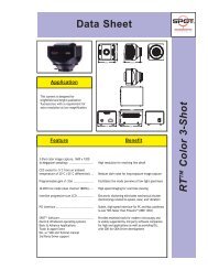
from overlapping dye emission spectra. For example, suppose a<br />
system is being configured to simultaneously count cells that have<br />
been tagged with a combination of FITC and PE. If either of these<br />
dyes were used alone, a good choice of emission filter would be a<br />
530BP50 for FITC and a 575BP40 for PE. see graph 1.<br />
These wide bands would very effectively collect the emission energy<br />
of each dye transmitting the peaks and much of each dye’s red tail.<br />
There is a possibility of two problems if used simultaneously. First,<br />
there will be signifi cant channel cross talk since the red edge of the<br />
530BP50 FITC filter would be coincident with the blue edge of the<br />
575BP40 PE filter. Second, because the red tail of FITC overlaps with<br />
most of the PE emission, a high percentage of color correction will be<br />
needed to remove the input that the FITC tail will make to the signal<br />
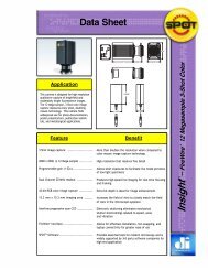
recorded by the PE channel. A narrower FITC filter (XCY-525BP30)<br />
that cuts off at 535 nm would provide good channel separation.<br />
see graph 2.<br />
Graph 1<br />
Transmission (%)<br />
100<br />
90<br />
80<br />
70<br />
60<br />
50<br />
40<br />
Possible Filter Configuration for Multi-fluor Analysis<br />
NON OPTIMIZED<br />
FITC Emission<br />
PE Emission<br />
530BP50 Filter<br />
575BP40 Filter<br />
This will not however reduce the need for color compensation. To<br />
achieve this, a narrower PE filter is required. By moving the blue<br />
edge of the PE filter to 565 nm and the red edge to 585 nm,<br />
Omega Optical recommends the resulting XCY-574BP26 filter, which<br />
transmits the peak of the PE emission spectrum. Because it is more<br />
selective for PE, it transmits much less of the FITC red tail. The result<br />
is that the need for compensation due to FITC in the PE channel<br />
will be greatly reduced.<br />
The selection of emission band placment and width is made more<br />
complicated by the presence of multiple excitation lasers. If all<br />
of the sources are on simultaneously, then in addition to cross talk<br />
and color compensation concerns, the <strong>interference</strong> <strong>filters</strong> will need<br />
to block all excitation wavelengths to OD5 or greater. If the lasers<br />
are fired sequentially, the complexity is reduced since each emission<br />
filter need only provide deep blocking for the laser that is on at the<br />
Transmission (%)<br />
Possible Filter Configuration for Multi-fluor Analysis<br />
particular time a given channel is collecting energy.<br />
100<br />
90<br />
80<br />
70<br />
60<br />
50<br />
Graph<br />
40<br />
2<br />
30<br />
20 100<br />
10<br />
Transmission (%)<br />
90<br />
Transmission (%)<br />
100<br />
90<br />
80<br />
70<br />
60<br />
50<br />
40<br />
30<br />
20<br />
10<br />
Possible<br />
NON<br />
Filter<br />
OPTIMIZED<br />
Configuration for Multi-fluor Analysis<br />
OPTIMIZED<br />
Possible Filter Configuration for Multi-fluor Analysis<br />
OPTIMIZED<br />
0<br />
80<br />
400 450 0<br />
500 550 600 650 700 750<br />
Wavelength 500 (nm) 550 400 450 600 650 700 750<br />
70<br />
Wavelength (nm)<br />
60<br />
50<br />
40<br />
FITC Emission<br />
PE Emission<br />
XCY-525BP30<br />
XCY-574BP26<br />
mission<br />
ssion<br />
0 Filter<br />
0 Filter<br />
30<br />
20<br />
10<br />
0<br />
400 450 500 550 600 650 700 750<br />
Wavelength (nm)<br />
30<br />
20<br />
10<br />
0<br />
400 450 500 550 600 650 700 750<br />
Wavelength (nm)<br />
FITC Emission<br />
PE Emission<br />
XCY-525BP30<br />
XCY-574BP26<br />
For current product listings, specifications, and pricing:<br />
www.omega<strong>filters</strong>.com • sales@omega<strong>filters</strong>.com<br />
1.866.488.1064 (toll free within USA only) • +1.802.254.2690 (outside USA)<br />
85