Planar UltraRes Series Manual
Planar UltraRes Series Manual
Planar UltraRes Series Manual

Create successful ePaper yourself
Turn your PDF publications into a flip-book with our unique Google optimized e-Paper software.
<strong>Planar</strong> <strong>UltraRes</strong> TM User<br />
<strong>Manual</strong>
Copyright © 6 Jun 2013 by <strong>Planar</strong> Systems, Inc. All rights reserved.<br />
Contents of this publication may not be reproduced in any form without permission of <strong>Planar</strong><br />
Systems, Inc.<br />
Trademark Credits<br />
Windows is a trademark of Microsoft Corp.<br />
<strong>Planar</strong>'s Big Picture is a trademark of <strong>Planar</strong> Systems, Inc.<br />
All other names are trademarks or registered trademarks of their respective companies.<br />
Disclaimer<br />
The information contained in this document is subject to change without notice. <strong>Planar</strong><br />
Systems, Inc. makes no warranty of any kind with regard to this material. While every<br />
precaution has been taken in the preparation of this manual, the Company shall not be liable<br />
for errors or omissions contained herein or for incidental or consequential damages in<br />
connection with the furnishing, performance, or use of this material.<br />
Warranty and Service Plans<br />
<strong>Planar</strong> warranty and service plans will help you maximize your investment by providing great<br />
support, display uptime, and performance optimization. From post-sale technical support to<br />
a full suite of depot services, our services are performed by trained <strong>Planar</strong> employees. When<br />
you purchase a <strong>Planar</strong> product, you get more than a display, you get the service and support<br />
you need to maximize your investment. To find the latest warranty and service information<br />
regarding your <strong>Planar</strong> product, please visit http://www.planarcontrolroom.com/support<br />
RoHS Compliance Statement<br />
The <strong>Planar</strong> <strong>UltraRes</strong> 4K professional displays are fully RoHS compliant.<br />
ADA Compliance Statement<br />
All <strong>Planar</strong> <strong>UltraRes</strong> 4K professional displays are compliant with the Americans with<br />
Disabilities Act.<br />
Part Number: 020-1229-01A
Table of Contents<br />
Introduction . . . . . . . . . . . . . . . . . . . . . . . . . . . . . . . . . . . . . . . . . . . . . . . . . . . . . . . . . . . . . . . . . . . . . . . . . . . . . . . . . . . . . . .1<br />
Important Safety Instructions . . . . . . . . . . . . . . . . . . . . . . . . . . . . . . . . . . . . . . . . . . . . . . . . . . . . . . . . . . . . . . .2<br />
European Union Disposal Information. . . . . . . . . . . . . . . . . . . . . . . . . . . . . . . . . . . . . . . . . . . . . . . . . . . . . . .4<br />
Recommended Usage . . . . . . . . . . . . . . . . . . . . . . . . . . . . . . . . . . . . . . . . . . . . . . . . . . . . . . . . . . . . . . . . . . . . . . . . . . . .5<br />
Burn-In Versus Temporary Image Retention . . . . . . . . . . . . . . . . . . . . . . . . . . . . . . . . . . . . . . . . . . . . . . . . .5<br />
Normal Use Thermal Guidelines . . . . . . . . . . . . . . . . . . . . . . . . . . . . . . . . . . . . . . . . . . . . . . . . . . . . . . . . . . . . .6<br />
Basic Concept of <strong>Planar</strong> <strong>UltraRes</strong> Display . . . . . . . . . . . . . . . . . . . . . . . . . . . . . . . . . . . . . . . . . . . . . . . . . . . . . . . . . .7<br />
Using the Remote Control . . . . . . . . . . . . . . . . . . . . . . . . . . . . . . . . . . . . . . . . . . . . . . . . . . . . . . . . . . . . . . . . . . . . . . . .8<br />
Powering On/Off <strong>Planar</strong> <strong>UltraRes</strong> Displays . . . . . . . . . . . . . . . . . . . . . . . . . . . . . . . . . . . . . . . . . . . . . . . . . . . . . . . . .9<br />
<strong>Planar</strong> <strong>UltraRes</strong> in Standby Mode. . . . . . . . . . . . . . . . . . . . . . . . . . . . . . . . . . . . . . . . . . . . . . . . . . . . . . . . . . 10<br />
Input Setup . . . . . . . . . . . . . . . . . . . . . . . . . . . . . . . . . . . . . . . . . . . . . . . . . . . . . . . . . . . . . . . . . . . . . . . . . . . . . . . . . . . . 11<br />
Supported Formats for Multiple Inputs . . . . . . . . . . . . . . . . . . . . . . . . . . . . . . . . . . . . . . . . . . . . . . . . . . . . 11<br />
Supported Formats for Single Inputs . . . . . . . . . . . . . . . . . . . . . . . . . . . . . . . . . . . . . . . . . . . . . . . . . . . . . . 11<br />
Installing a <strong>Planar</strong> <strong>UltraRes</strong> Display. . . . . . . . . . . . . . . . . . . . . . . . . . . . . . . . . . . . . . . . . . . . . . . . . . . . . . . . . . . . . . 13<br />
Before You Begin . . . . . . . . . . . . . . . . . . . . . . . . . . . . . . . . . . . . . . . . . . . . . . . . . . . . . . . . . . . . . . . . . . . . . . . . . . . . . . . 13<br />
Tools/Equipment List . . . . . . . . . . . . . . . . . . . . . . . . . . . . . . . . . . . . . . . . . . . . . . . . . . . . . . . . . . . . . . . . . . . . . 13<br />
Other Things You May Need . . . . . . . . . . . . . . . . . . . . . . . . . . . . . . . . . . . . . . . . . . . . . . . . . . . . . . . . . . . . . . 13<br />
Plan Your Installation . . . . . . . . . . . . . . . . . . . . . . . . . . . . . . . . . . . . . . . . . . . . . . . . . . . . . . . . . . . . . . . . . . . . . 13<br />
Supported Graphics Cards . . . . . . . . . . . . . . . . . . . . . . . . . . . . . . . . . . . . . . . . . . . . . . . . . . . . . . . . . . . . . . . . . . . . . . 14<br />
Setting Up AMD Graphics Cards For 3D Content . . . . . . . . . . . . . . . . . . . . . . . . . . . . . . . . . . . . . . . . . . . 15<br />
Setting Up NVIDIA Graphics Cards. . . . . . . . . . . . . . . . . . . . . . . . . . . . . . . . . . . . . . . . . . . . . . . . . . . . . . . . . 16<br />
Recommended PCs. . . . . . . . . . . . . . . . . . . . . . . . . . . . . . . . . . . . . . . . . . . . . . . . . . . . . . . . . . . . . . . . . . . . . . . . . . . . . 16<br />
Unpacking and Checking Accessories . . . . . . . . . . . . . . . . . . . . . . . . . . . . . . . . . . . . . . . . . . . . . . . . . . . . . . . . . . . 17<br />
LCD Module Box. . . . . . . . . . . . . . . . . . . . . . . . . . . . . . . . . . . . . . . . . . . . . . . . . . . . . . . . . . . . . . . . . . . . . . . . . . 17<br />
Accessory Kit . . . . . . . . . . . . . . . . . . . . . . . . . . . . . . . . . . . . . . . . . . . . . . . . . . . . . . . . . . . . . . . . . . . . . . . . . . . . . 19<br />
LCD Installation . . . . . . . . . . . . . . . . . . . . . . . . . . . . . . . . . . . . . . . . . . . . . . . . . . . . . . . . . . . . . . . . . . . . . . . . . . . . . . . . . . 21<br />
Installing an <strong>UltraRes</strong> Display on a Wall. . . . . . . . . . . . . . . . . . . . . . . . . . . . . . . . . . . . . . . . . . . . . . . . . . . . . . . . . . 22<br />
Using the Kickstand Bracket. . . . . . . . . . . . . . . . . . . . . . . . . . . . . . . . . . . . . . . . . . . . . . . . . . . . . . . . . . . . . . . 29<br />
<strong>Planar</strong> <strong>UltraRes</strong> User <strong>Manual</strong><br />
i
Table of Contents<br />
Connections . . . . . . . . . . . . . . . . . . . . . . . . . . . . . . . . . . . . . . . . . . . . . . . . . . . . . . . . . . . . . . . . . . . . . . . . . . . . . . . . . . . .30<br />
Connecting AC Power . . . . . . . . . . . . . . . . . . . . . . . . . . . . . . . . . . . . . . . . . . . . . . . . . . . . . . . . . . . . . . . . . . . . .30<br />
Connecting the Wired IR Module. . . . . . . . . . . . . . . . . . . . . . . . . . . . . . . . . . . . . . . . . . . . . . . . . . . . . . . . . . .30<br />
Connecting Sources . . . . . . . . . . . . . . . . . . . . . . . . . . . . . . . . . . . . . . . . . . . . . . . . . . . . . . . . . . . . . . . . . . . . . . .31<br />
Setting Up <strong>UltraRes</strong> Using Multiple Inputs . . . . . . . . . . . . . . . . . . . . . . . . . . . . . . . . . . . . . . . . . . . . . . . . . .32<br />
Setting Up <strong>UltraRes</strong> Using Single Inputs . . . . . . . . . . . . . . . . . . . . . . . . . . . . . . . . . . . . . . . . . . . . . . . . . . . .35<br />
Installing the <strong>UltraRes</strong> Control Software . . . . . . . . . . . . . . . . . . . . . . . . . . . . . . . . . . . . . . . . . . . . . . . . . . . . . . . . .39<br />
Installing USB Drivers. . . . . . . . . . . . . . . . . . . . . . . . . . . . . . . . . . . . . . . . . . . . . . . . . . . . . . . . . . . . . . . . . . . . . . . . . . . .42<br />
Using the <strong>UltraRes</strong> Control Software . . . . . . . . . . . . . . . . . . . . . . . . . . . . . . . . . . . . . . . . . . . . . . . . . . . . . . . . . . . . .43<br />
Setting Up Sources . . . . . . . . . . . . . . . . . . . . . . . . . . . . . . . . . . . . . . . . . . . . . . . . . . . . . . . . . . . . . . . . . . . . . . . . . . . . . .45<br />
Auto Power Off Timer . . . . . . . . . . . . . . . . . . . . . . . . . . . . . . . . . . . . . . . . . . . . . . . . . . . . . . . . . . . . . . . . . . . . . . . . . . .46<br />
Standby Mode . . . . . . . . . . . . . . . . . . . . . . . . . . . . . . . . . . . . . . . . . . . . . . . . . . . . . . . . . . . . . . . . . . . . . . . . . . . . . . . . . .46<br />
Changing Backlight Intensity . . . . . . . . . . . . . . . . . . . . . . . . . . . . . . . . . . . . . . . . . . . . . . . . . . . . . . . . . . . . . . . . . . . .47<br />
Turning Local Dimming On or Off. . . . . . . . . . . . . . . . . . . . . . . . . . . . . . . . . . . . . . . . . . . . . . . . . . . . . . . . . . . . . . . .47<br />
Changing Frame Delay . . . . . . . . . . . . . . . . . . . . . . . . . . . . . . . . . . . . . . . . . . . . . . . . . . . . . . . . . . . . . . . . . . . . . . . . . .47<br />
Upgrading Firmware . . . . . . . . . . . . . . . . . . . . . . . . . . . . . . . . . . . . . . . . . . . . . . . . . . . . . . . . . . . . . . . . . . . . . . . . . . . .48<br />
Error Codes . . . . . . . . . . . . . . . . . . . . . . . . . . . . . . . . . . . . . . . . . . . . . . . . . . . . . . . . . . . . . . . . . . . . . . . . . . . . . . . . . . . . .51<br />
Network Settings . . . . . . . . . . . . . . . . . . . . . . . . . . . . . . . . . . . . . . . . . . . . . . . . . . . . . . . . . . . . . . . . . . . . . . . . . . . . . . . . .53<br />
DHCP Network Setup. . . . . . . . . . . . . . . . . . . . . . . . . . . . . . . . . . . . . . . . . . . . . . . . . . . . . . . . . . . . . . . . . . . . . . . . . . . .53<br />
Static IP Network Setup . . . . . . . . . . . . . . . . . . . . . . . . . . . . . . . . . . . . . . . . . . . . . . . . . . . . . . . . . . . . . . . . . . . . . . . . .55<br />
<strong>Planar</strong> <strong>UltraRes</strong> Remote Monitoring Software . . . . . . . . . . . . . . . . . . . . . . . . . . . . . . . . . . . . . . . . . . . . . . . . . . . .59<br />
Remote Monitoring Home. . . . . . . . . . . . . . . . . . . . . . . . . . . . . . . . . . . . . . . . . . . . . . . . . . . . . . . . . . . . . . . . . . . . . . .59<br />
Remote Monitoring Unit Status . . . . . . . . . . . . . . . . . . . . . . . . . . . . . . . . . . . . . . . . . . . . . . . . . . . . . . . . . . . . . . . . . .60<br />
Remote Monitoring Display Control . . . . . . . . . . . . . . . . . . . . . . . . . . . . . . . . . . . . . . . . . . . . . . . . . . . . . . . . . . . . .60<br />
Remote Monitoring Power On/Off . . . . . . . . . . . . . . . . . . . . . . . . . . . . . . . . . . . . . . . . . . . . . . . . . . . . . . . . .61<br />
Remote Monitoring Source Setup. . . . . . . . . . . . . . . . . . . . . . . . . . . . . . . . . . . . . . . . . . . . . . . . . . . . . . . . . . . . . . . .62<br />
Remote Monitoring Advanced Setup . . . . . . . . . . . . . . . . . . . . . . . . . . . . . . . . . . . . . . . . . . . . . . . . . . . . . . . . . . . .63<br />
Remote Monitoring Admin Setup. . . . . . . . . . . . . . . . . . . . . . . . . . . . . . . . . . . . . . . . . . . . . . . . . . . . . . . . . . . . . . . .63<br />
ii<br />
<strong>Planar</strong> <strong>UltraRes</strong> User <strong>Manual</strong>
Table of Contents<br />
Remote Monitoring Network Setup . . . . . . . . . . . . . . . . . . . . . . . . . . . . . . . . . . . . . . . . . . . . . . . . . . . . . . . . . . . . . 64<br />
Remote Monitoring Date and Time. . . . . . . . . . . . . . . . . . . . . . . . . . . . . . . . . . . . . . . . . . . . . . . . . . . . . . . . 66<br />
Remote Monitoring Access Control. . . . . . . . . . . . . . . . . . . . . . . . . . . . . . . . . . . . . . . . . . . . . . . . . . . . . . . . 67<br />
Remote Monitoring Software Setup (Upgrading Network Firmware) . . . . . . . . . . . . . . . . . . . . . . . 68<br />
Remote Monitoring Reboot. . . . . . . . . . . . . . . . . . . . . . . . . . . . . . . . . . . . . . . . . . . . . . . . . . . . . . . . . . . . . . . . . . . . . 69<br />
External Control . . . . . . . . . . . . . . . . . . . . . . . . . . . . . . . . . . . . . . . . . . . . . . . . . . . . . . . . . . . . . . . . . . . . . . . . . . . . . . . . . 71<br />
RS232 Communication . . . . . . . . . . . . . . . . . . . . . . . . . . . . . . . . . . . . . . . . . . . . . . . . . . . . . . . . . . . . . . . . . . . . . . . . . 72<br />
Connecting the RS232 Cable . . . . . . . . . . . . . . . . . . . . . . . . . . . . . . . . . . . . . . . . . . . . . . . . . . . . . . . . . . . . . . 72<br />
Setting Up Multiple Inputs Using RS232 Commands . . . . . . . . . . . . . . . . . . . . . . . . . . . . . . . . . . . . . . . 72<br />
Setting Up Single Inputs Using RS232 Commands . . . . . . . . . . . . . . . . . . . . . . . . . . . . . . . . . . . . . . . . . 73<br />
RS232 Commands . . . . . . . . . . . . . . . . . . . . . . . . . . . . . . . . . . . . . . . . . . . . . . . . . . . . . . . . . . . . . . . . . . . . . . . . . . . . . . 74<br />
RS232 Command Format . . . . . . . . . . . . . . . . . . . . . . . . . . . . . . . . . . . . . . . . . . . . . . . . . . . . . . . . . . . . . . . . . . . . . . . 74<br />
RS232 Response Format . . . . . . . . . . . . . . . . . . . . . . . . . . . . . . . . . . . . . . . . . . . . . . . . . . . . . . . . . . . . . . . . . . . . . . . . 75<br />
RS232 Command/Response Examples . . . . . . . . . . . . . . . . . . . . . . . . . . . . . . . . . . . . . . . . . . . . . . . . . . . . . . . . . . 76<br />
Supported <strong>UltraRes</strong> RS232 Commands . . . . . . . . . . . . . . . . . . . . . . . . . . . . . . . . . . . . . . . . . . . . . . . . . . . . . . . . . . 77<br />
SNMP Monitoring . . . . . . . . . . . . . . . . . . . . . . . . . . . . . . . . . . . . . . . . . . . . . . . . . . . . . . . . . . . . . . . . . . . . . . . . . . . . . . 80<br />
Sending RS232 Commands Via UDP. . . . . . . . . . . . . . . . . . . . . . . . . . . . . . . . . . . . . . . . . . . . . . . . . . . . . . . . . . . . . 81<br />
Using Discrete IR Codes. . . . . . . . . . . . . . . . . . . . . . . . . . . . . . . . . . . . . . . . . . . . . . . . . . . . . . . . . . . . . . . . . . . . . . . . . 82<br />
IR Command Protocol . . . . . . . . . . . . . . . . . . . . . . . . . . . . . . . . . . . . . . . . . . . . . . . . . . . . . . . . . . . . . . . . . . . . 82<br />
Supported <strong>UltraRes</strong> IR Commands . . . . . . . . . . . . . . . . . . . . . . . . . . . . . . . . . . . . . . . . . . . . . . . . . . . . . . . . 83<br />
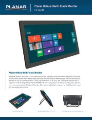
Specifications . . . . . . . . . . . . . . . . . . . . . . . . . . . . . . . . . . . . . . . . . . . . . . . . . . . . . . . . . . . . . . . . . . . . . . . . . . . . . . . . . . . . 85<br />
Signal Compatibility . . . . . . . . . . . . . . . . . . . . . . . . . . . . . . . . . . . . . . . . . . . . . . . . . . . . . . . . . . . . . . . . . . . . . . . . . . . . 87<br />
<strong>UltraRes</strong> Dimensions. . . . . . . . . . . . . . . . . . . . . . . . . . . . . . . . . . . . . . . . . . . . . . . . . . . . . . . . . . . . . . . . . . . . . . . . . . . . . 89<br />
Display Dimensions - Front, Side and Top Views . . . . . . . . . . . . . . . . . . . . . . . . . . . . . . . . . . . . . . . . . . . . . . . . . 89<br />
Display Dimensions - Rear View . . . . . . . . . . . . . . . . . . . . . . . . . . . . . . . . . . . . . . . . . . . . . . . . . . . . . . . . . . . . . . . . . 90<br />
Rear View - Wall Mount Hangers and Service Panel Locations . . . . . . . . . . . . . . . . . . . . . . . . . . . . . . 91<br />
Landscape Wall Mounts - Front and Bottom Views. . . . . . . . . . . . . . . . . . . . . . . . . . . . . . . . . . . . . . . . . . . . . . . 92<br />
Landscape Wall Mounts - Sides Views . . . . . . . . . . . . . . . . . . . . . . . . . . . . . . . . . . . . . . . . . . . . . . . . . . . . . . . . . . . 93<br />
Portrait Wall Mounts - Front View . . . . . . . . . . . . . . . . . . . . . . . . . . . . . . . . . . . . . . . . . . . . . . . . . . . . . . . . . . . . . . . 94<br />
<strong>Planar</strong> <strong>UltraRes</strong> User <strong>Manual</strong><br />
iii
Table of Contents<br />
Portrait Wall Mounts - Sides Views . . . . . . . . . . . . . . . . . . . . . . . . . . . . . . . . . . . . . . . . . . . . . . . . . . . . . . . . . . . . . . .95<br />
Optional Pedestal Mount - Front View . . . . . . . . . . . . . . . . . . . . . . . . . . . . . . . . . . . . . . . . . . . . . . . . . . . . . . . . . . .96<br />
Optional Pedestal Mount - Top and Bottom Views. . . . . . . . . . . . . . . . . . . . . . . . . . . . . . . . . . . . . . . . . . . . . . . .97<br />
Optional Pedestal Mount - Single and Double Sided. . . . . . . . . . . . . . . . . . . . . . . . . . . . . . . . . . . . . . . . . . . . . .98<br />
Optional Pedestal Mount - Double Sided in Service Position . . . . . . . . . . . . . . . . . . . . . . . . . . . . . . . . . . . . . .99<br />
Troubleshooting During Installation . . . . . . . . . . . . . . . . . . . . . . . . . . . . . . . . . . . . . . . . . . . . . . . . . . . . . . . . . . . 101<br />
<strong>UltraRes</strong> LED Codes . . . . . . . . . . . . . . . . . . . . . . . . . . . . . . . . . . . . . . . . . . . . . . . . . . . . . . . . . . . . . . . . . . . . . . . . . . . 101<br />
Error Codes in the <strong>UltraRes</strong> Control Software . . . . . . . . . . . . . . . . . . . . . . . . . . . . . . . . . . . . . . . . . . . . . . . . . . . 102<br />
Symptoms, Possible Causes and Solutions . . . . . . . . . . . . . . . . . . . . . . . . . . . . . . . . . . . . . . . . . . . . . . . . . . . . . 104<br />
Symptom: Can’t Get PC to Output 4K @ 24/30Hz . . . . . . . . . . . . . . . . . . . . . . . . . . . . . . . . . . . . . . . . . 104<br />
Symptom: Can’t Get PC to Output 4K @ 60Hz. . . . . . . . . . . . . . . . . . . . . . . . . . . . . . . . . . . . . . . . . . . . . 105<br />
Symptom: My Scheduled Network Power On/Off Settings Aren’t Working . . . . . . . . . . . . . . . . . 106<br />
Symptom: IR Isn’t Working Properly . . . . . . . . . . . . . . . . . . . . . . . . . . . . . . . . . . . . . . . . . . . . . . . . . . . . . . 106<br />
Accessing <strong>Planar</strong>’s Technical Support Website. . . . . . . . . . . . . . . . . . . . . . . . . . . . . . . . . . . . . . . . . . . . . . . . . . 107<br />
Downloading Additional Documentation and Firmware . . . . . . . . . . . . . . . . . . . . . . . . . . . . . . . . . . . . . . . . 107<br />
Downloading Utility Software . . . . . . . . . . . . . . . . . . . . . . . . . . . . . . . . . . . . . . . . . . . . . . . . . . . . . . . . . . . . . . . . . 107<br />
Regulatory Information. . . . . . . . . . . . . . . . . . . . . . . . . . . . . . . . . . . . . . . . . . . . . . . . . . . . . . . . . . . . . . . . . . . . . . . . . 109<br />
iv<br />
<strong>Planar</strong> <strong>UltraRes</strong> User <strong>Manual</strong>
Introduction<br />
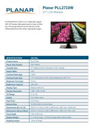
<strong>Planar</strong> <strong>UltraRes</strong> 4K professional display is a family of 84” Ultra HD displays that<br />
produce resolution and picture quality not before seen in large format LCD displays.<br />
There are three different offerings: the UR8450-LX, UR8450-MX and the UR8450-3D.<br />
Designed specifically for resolution-rich commercial applications, <strong>Planar</strong> <strong>UltraRes</strong><br />
displays offer the image quality, connectivity, industrial design and configuration<br />
options required in leading control rooms, collaboration rooms and digital branding<br />
installations.<br />
Some of the features of the <strong>UltraRes</strong> display are:<br />
• Ultra HD (3840 x 2160) resolution @ 120Hz vertical refresh<br />
• Outstanding picture quality - 4x pixel density of a comparably-sized Full HD<br />
display<br />
• Slim design with <strong>Planar</strong> Profile TM Mounting System (about 3” deep when<br />
mounted)<br />
• Supports range of 4K sources and timings<br />
• Energy-saving features include LEDs,
Important Safety Instructions<br />
1 Read these instructions.<br />
2 Keep these instructions.<br />
3 Heed all warnings.<br />
4 Follow all instructions.<br />
5 Do not use any of the <strong>Planar</strong> <strong>UltraRes</strong> products near water.<br />
6 Clean the LCD screens with an LCD screen cleaner or LCD wipes.<br />
7 Do not install near any heat sources such as radiators, heat registers, stoves or<br />
other apparatus (including amplifiers) that produce heat.<br />
8 Do not defeat the safety purpose of the polarized or grounding type plug. A<br />
polarized plug has two blades with one wider than the other. A grounding type<br />
plug has two blades and a third grounding prong. The wide blade or the third<br />
prong is provided for your safety. When the provided plug does not fit into your<br />
outlet, consult an electrician for the replacement of the obsolete outlet.<br />
9 Protect the power cord from being walked on or pinched particularly at plugs,<br />
convenience receptacles and the point where they exit from any of the <strong>Planar</strong><br />
<strong>UltraRes</strong> products.<br />
10 Only use the attachments/accessories specified by the manufacturer.<br />
11 Unplug all <strong>Planar</strong> <strong>UltraRes</strong> displays during lightning storms or when unused for<br />
long periods of time.<br />
12 You must follow all National Electrical Code regulations. In addition, be aware of<br />
local codes and ordinances when installing your system.<br />
13 Refer all servicing to qualified service personnel. Servicing is required when any<br />
of the <strong>Planar</strong> <strong>UltraRes</strong> products have been damaged in any way, such as the AC<br />
power cord or plug is damaged, liquid has been spilled or objects have fallen into<br />
a product, the products have been exposed to rain or moisture, do not operate<br />
normally or have been dropped.<br />
14 Keep the packing material in case the equipment should ever need to be<br />
shipped.<br />
15 Wall mounts must be secure. The wall must be strong enough to hold the<br />
<strong>UltraRes</strong> display, mounts and cables.<br />
2 <strong>Planar</strong> <strong>UltraRes</strong> User <strong>Manual</strong>
16 Slight pressure on the LCD will cause distortion of the image. Heavier pressure<br />
will cause permanent damage. <strong>Planar</strong> <strong>UltraRes</strong> configurations should be<br />
mounted where viewers cannot touch the screen or insert small objects in the<br />
openings that will create hazards by contacting bare conductive parts.<br />
Caution: The front polarizer is soft and subject to scratches from sharp objects.<br />
17 The polarizer is a thin sheet of film laminated to the outside layer of glass on the<br />
LCD screen. Take care when handling items near the screen.<br />
<strong>Planar</strong> <strong>UltraRes</strong> User <strong>Manual</strong> 3
European Union Disposal Information<br />
English<br />
■ Disposal of old Electrical & Electronic Equipment (Applicable throughout<br />
the European Union and other European countries with separate collection<br />
programs)<br />
This symbol found on your product or on its packaging, indicates that<br />
this product should not be treated as household waste when you wish to<br />
dispose of it. Instead, it should be handed over to an applicable collection<br />
point for the recycling of electrical and electronic equipment. By ensuring<br />
this product is disposed of correctly, you will help prevent potential<br />
negative consequences to the environment and human health, which<br />
could otherwise be caused by inappropriate disposal of this product. The<br />
recycling of materials will help to conserve natural resources.<br />
Français<br />
■ Mise au rebut des équipements électriques et électroniques usagés<br />
(Valable dans l’ensemble de l’Union Européenne ainsi que dans les pays<br />
européens disposant de programmes distincts de collecte des déchets)<br />
Ce symbole appliqué sur votre produit ou sur son emballage indique<br />
que ce produit ne doit pas être traité comme un déchet ménager lorsque<br />
vous voulez le mettre au rebut. Il doit au contraire être remis à un site<br />
de collecte agréé pour le recyclage des équipements électriques et<br />
électroniques. En veillant à ce que ce produit soit mis au rebut de façon<br />
adéquate, vous contribuerez à prévenir les conséquences potentiellement<br />
négatives sur l’environnement et sur la santé humaine qui risqueraient<br />
de se produire en cas de mise au rebut inappropriée de ce produit. Le<br />
recyclage des matériaux contribuera également à économiser les ressources<br />
naturelles.<br />
Deutsch<br />
■ Entsorgung von elektrischen & elektronischen Altgeräten (geltend für die<br />
europäische Gemeinschaft und andere europäische Länder mit separaten<br />
Sammelprogrammen)<br />
Dieses Symbol, zu finden auf Ihrem Produkt oder dessen Verpackung,<br />
macht Sie darauf aufmerksam, dass dieses Produkt bei der Entsorgung<br />
nicht als Hausmüll behandelt werden darf. Statt dessen sollte es an eine<br />
Sammelstelle zum Recycling von elektrischen und elektronischen Altgeräten<br />
gegeben werden. Helfen Sie mit, potenziell schädliche Einflüsse<br />
auf Umwelt und Gesundheit, die durch eine unsachgemäße Entsorgung<br />
dieses Produktes entstehen können, zu vermeiden und entsorgen Sie<br />
dieses Produkt ordnungsgemäß. Recycling hilft, natürliche Rohstoffe<br />
einzusparen.<br />
This symbol is only valid in the European Union.<br />
If you wish to discard this product, please contact<br />
your local authorities or dealer and ask for the correct<br />
method of disposal.<br />
Ce symbole n’est valable que dans l’Union Européenne.<br />
Si vous souhaitez mettre ce produit au rebut, veuillez<br />
prendre contact avec les autorités locales ou avec votre<br />
revendeur et renseignez-vous sur la méthode de mise<br />
au rebut correcte.<br />
Dieses Symbol ist nur innerhalb der europäischen<br />
Gemeinschaft gültig.<br />
Wenn Sie dieses Produkt entsorgen möchten, wenden<br />
Sie sich bitte an Ihre örtliche Behörde und fragen Sie<br />
nach der ordnungsgemäßen Entsorgungsmethode.<br />
Español<br />
■ Deshecho de equipos eléctricos y electrónicos (aplicable a la Unión Europea<br />
y a otros países europeos con programas de reciclaje independientes)<br />
La presencia de este símbolo en el propio producto o en su material de<br />
embalaje, indica que no se debe tratar como residuo doméstico cuando<br />
desee deshacerse de él. En su lugar, debe entregarlo en el punto limpio<br />
correspondiente de reciclaje de equipos eléctricos y electrónicos. Asegurándose<br />
de que este producto se desecha de forma correcta, ayudará<br />
a evitar posibles consecuencias negativas para la conservación del<br />
medioambiente y la salud humana, consecuencias que podrían darse si<br />
se deshace del producto de forma inadecuada. El reciclado de materiales<br />
ayuda a conservar los recursos naturales.<br />
Italiano<br />
■ Smaltimento delle attrezzature elettriche ed elettroniche usate (applicabile<br />
in tutta la Comunità Europea ed altri Paesi Europei che applicano<br />
programmi di raccolta differenziata)<br />
Il simbolo trovato sul prodotto, o sulla sua confezione, indica che il<br />
prodotto non può essere trattato come i domestici quando è il momento<br />
di smaltirlo. Al contrario, deve essere consegnato ad un centro di raccolta<br />
specializzato nel riciclaggio di attrezzature elettriche ed elettroniche. Assicurando<br />
che il corretto smaltimento di questo prodotto, si aiuterà a prevenire<br />
potenziali conseguenze negative sull’ambiente e sulla salute umana,<br />
che possono essere provocate da uno scorretto smaltimento di questa<br />
attrezzatura. I materiali riciclati aiuteranno a conservare le risorse naturali.<br />
Nederlands<br />
■ Verwijderen van oude elektrische en elektronische apparatuur (toepasselijk<br />
in de volledige Europese Unie en andere Europese landen met<br />
afzonderlijke programma’s voor afvalverzameling)<br />
Dit symbool dat op het product of zijn verpakking is aangebracht, geeft aan<br />
dat dit product niet mag worden behandeld als huishoudelijk afval als u het<br />
wilt wegwerpen. U moet het afgeven bij een specifiek verzamelpunt voor<br />
de recyclage van elektrische en elektronische apparatuur. Door te garanderen<br />
dat u dit product op de correcte manier wegwerpt, helpt u potentiële<br />
negatieve gevolgen voor het milieu en de menselijke gezondheid, die<br />
zouden kunnen worden veroorzaakt door een onrechtmatig wegwerpen<br />
van het product, te voorkomen. De recyclage van materialen helpt het<br />
behoud van natuurlijke bronnen.<br />
Este símbolo solamente es válido en la Unión<br />
Europea.<br />
Si desea deshacerse de este producto, póngase<br />
en contacto con las autoridades locales o con su<br />
distribuidor y pida información sobre el método de<br />
disposición adecuado.<br />
Questo simbolo è valido solo nell’Unione Europea.<br />
Per smaltire questo prodotto, mettersi in contatto con<br />
le autorità locali – o con il rivenditore – e chiedere<br />
informazioni sul corretto metodo di smaltimento.<br />
Dit symbool is alleen geldig in de Europese Unie.<br />
Als u dit product wenst weg te gooien, dient u contact op<br />
te nemen met uw lokale instanties voor details over de<br />
gepaste methode voor afvalverwijdering.<br />
Português<br />
■ Eliminação de equipamentos eléctricos e electrónicos usados (aplicável<br />
na União Europeia e noutros países europeus com programas próprios de<br />
recolha destes equipamentos)<br />
Este símbolo, colocado no produto ou na respectiva embalagem, indica<br />
que o produto não deve ser tratado como lixo doméstico aquando da sua<br />
eliminação. Em vez disso, deve ser entregue num ponto de recolha de equipamentos<br />
eléctricos e electrónicos para posterior reciclagem. Ao garantir<br />
a correcta eliminação deste produto, estará a evitar consequências potencialmente<br />
negativas tanto para o ambiente como para a saúde humana. A<br />
reciclagem de materiais ajuda a preservar os recursos naturais.<br />
Este símbolo apenas é válido na União Europeia.<br />
Se quiser eliminar este produto, contacte as entidades<br />
locais ou o seu fornecedor para ficar a saber<br />
qual o método de eliminação correcto.<br />
■ Avfall av förbrukad elektrisk och elektronisk utrustning (Tillämpbart i<br />
hela Europeiska unionen och andra europeiska länder med separata<br />
samlingsprogram)<br />
Svenska<br />
Den här symbolen som finns på din product eller på dess förpackning<br />
påvisar att produkten inte ska behandlas som hushållsavfall när du vill<br />
slänga bort den. Istället ska den lämnas över till en lämplig uppsamlingspunkt<br />
för återvinning av elektriska och elektroniska utrustningar. Genom att<br />
tillförsäkra att den här produkten återvinns på ett riktigt sätt hjälper du till<br />
med att förhindra möjliga negative konsekvenser för miljön och mänsklig<br />
hälsa. Det kan annars orsakas på grund av olämplig sophantering av den<br />
här produkten. Återvinning av material kommer att hjälpa till att bevara<br />
naturtillgångar.<br />
Den här symbolen är endast giltig inom den<br />
Europeiska unionen.<br />
Om du vill slänga bort den här produkten ska du<br />
kontakta lokala myndigheter eller återförsäljar, och<br />
fråga efter lämplig avfallsmetod.<br />
Polski<br />
■ Usuwanie zużytego sprzętu elektrycznego i elektronicznego (Dotyczy<br />
krajów Unii Europejskiej i innych krajów europejskich z oddzielnymi<br />
programami zbiórki odpadów)<br />
Obecność tego symbolu na produkcie lub na opakowaniu z produktem<br />
oznacza, że tego produktu nie można wyrzucać razem z odpadkami<br />
domowymi. Należy go przekazać do punktu zbiórki w celu poddania<br />
recyklingowi podzespołów elektrycznych i elektronicznych. Usunięcie tego<br />
produktu w prawidłowy sposób, pomoże w zabezpieczeniu przed negatywnym<br />
wpływem odpadów na środowisko i zdrowie ludzi, powodowanym<br />
przez niewłaściwe usuwanie produktu. Przetwarzanie materiałów pomaga<br />
w zachowaniu zasobów naturalnych.<br />
Ten symbol obowiązuje wyłącznie w krajach Unii<br />
Europejskiej.<br />
Informacje dotyczące prawidłowej metody usunięcia<br />
tego produktu, można uzyskać u władz lokalnych lub<br />
u dostawcy.<br />
Suomi<br />
■ Vanhojen sähkö- ja elektroniikkalaitteiden hävittäminen (Soveltuva kaikkialla<br />
Euroopan unionin alueella, sekä muissa Euroopan maissa, joilla on<br />
erilliset keräysohjelmat)<br />
Jos tuotteessa tai sen pakkauksessa on tämä symboli, sitä ei pidä<br />
hävitettäessä käsitellä tavallisena kotitalousjätteenä, vaan se kuuluu toimittaa<br />
sähkö- ja elektroniikkalaitteiden kierrätyspisteeseen. Varmistamalla,<br />
että tämä tuote hävitetään asiaankuuluvalla tavalla autat estämään mahdollisia<br />
ympäristölle ja ihmisille koituvia negatiivisia seuraamuksia, joita<br />
sen vääränlainen hävittäminen voi aiheuttaa. Materiaalien kierrättäminen<br />
auttaa säilyttämään luonnonvaroja.<br />
Tämä symboli on voimassa ainoastaan Euroopan<br />
unionin alueella.<br />
Jos haluat hävittää tämän tuotteen, ota yhteyttä<br />
paikallisiin viranomaisiin tai jälleenmyyjään ja tiedustele<br />
asiaankuuluvia hävittämistoimenpiteitä.<br />
Waste Electrical and Electronic Equipment (WEEE) Directive<br />
In the European Union, this label indicates that this product<br />
should not be disposed of with household waste. It should<br />
be deposited at an appropriate facility to enable recovery<br />
and recycling. EEE complies with Directive ‘Regulation on<br />
the Restriction of the Use of Certain Hazardous Substances<br />
in Electrical and Electronic Equipment’<br />
Waste Electrical and Electronic Equipment<br />
(WEEE) Directive In the European Union, this<br />
label indicates that this product should not be<br />
disposed of with household waste. It should be<br />
deposited at an appropriate facility to enable<br />
recovery and recycling. EEE complies with<br />
Directive ‘Regulation on the Restriction of the<br />
Use of Certain Hazardous Substances in<br />
Electrical and Electronic Equipment’<br />
Waste Electrical and Electronic Equipment (WEEE)<br />
Yönergeleri Avrupa Birliği'nde bu etiket, ürünün ev<br />
elektroniği aletleri atıkları ile imha edilemeyeceğini gösterir.<br />
Kurtarmak ve geri dönüşümünü sağlamak için uygun<br />
şartlarda saklanması gerekir. EEE Yönetmeliğine Uygundur<br />
Ve Elektronik Eşyalarda Bazi Zararli Maddelerin Kullaniminin<br />
Sinirlandirilmasina Dair Yönetmelik.<br />
Waste Electrical and Electronic Equipment<br />
(WEEE) Yönergeleri Avrupa Birliği'nde bu etiket,<br />
ürünün ev elektroniği aletleri atıkları ile imha<br />
edilemeyeceğini gösterir. Kurtarmak ve geri<br />
dönüşümünü sağlamak için uygun şartlarda<br />
saklanması gerekir. EEE Yönetmeliğine<br />
Uygundur Ve Elektronik Eşyalarda Bazi Zararli<br />
Maddelerin Kullaniminin Sinirlandirilmasina<br />
Dair Yönetmelik.<br />
4 <strong>Planar</strong> <strong>UltraRes</strong> User <strong>Manual</strong>
Recommended Usage<br />
Recommended Usage<br />
In order to get the most out of your LCD modules, use the following recommended<br />
guidelines to optimize the display.<br />
Burn-In Versus Temporary Image Retention<br />
Burn-in causes the screen to retain an image essentially forever, with little or no way<br />
to correct the problem. Under normal use, an LCD module will not experience burnin,<br />
as plasma displays do, nor will it retain images in any way.<br />
Normal use of an LCD module is defined as displaying continuously changing video<br />
patterns or images. However, LCD modules can experience temporary image<br />
retention when recommended usage guidelines are not followed.<br />
What is Temporary Image Retention?<br />
Temporary image retention (TIR) can occur when a static image is displayed<br />
continuously for extended periods of time. An electrical charge differential may build<br />
up between the electrodes of the liquid crystal, which causes a negative-color video<br />
image (color-inverted and brightness-inverted version of the previous image) to be<br />
retained when a new image is displayed. This behavior is true for any LCD device<br />
from any LCD manufacturer.<br />
TIR is not covered under warranty. See standard warranty terms and conditions for<br />
details. Here are some guidelines to help you avoid TIR:<br />
• Use the LCD module to show a screen saver, moving images or still pictures that<br />
change regularly. When using high-contrast images, reposition the images<br />
frequently.<br />
• Turn off the <strong>Planar</strong> <strong>UltraRes</strong> when it is not in use.<br />
Caution: For optimal performance, we suggest turning off the LED power on the <strong>Planar</strong><br />
<strong>UltraRes</strong> for four hours per day.<br />
<strong>Planar</strong> <strong>UltraRes</strong> User <strong>Manual</strong> 5
Recommended Usage<br />
Normal Use Thermal Guidelines<br />
Normal use of the LCD module is defined as operating in the open air to prevent heat<br />
buildup, and without direct or indirect heat sources such as lighting fixtures, heating<br />
ducts, or direct sunlight that can cause the modules to experience high operating<br />
temperatures. If the LCD module will be installed in a recessed area with an LCD<br />
surround or enclosure, ensure adequate openings are applied for proper air flow and<br />
ventilation.<br />
At 3000 meters or below, the maximum ambient operating temperature for the LCD<br />
module cannot be above 40º C nor below the minimum ambient operating<br />
temperature of 0º C. If one of these conditions exists, it is up to the installer to ensure<br />
that module placement is changed, thermal shielding is provided and/or additional<br />
ventilation is provided to keep the display within its nominal operating parameters.<br />
Cooling Requirements<br />
For optimal performance, active cooling by the installer should be planned for when<br />
the ambient temperature anywhere in the wall is predicted to be above the specified<br />
ambient temperature for the display.<br />
6 <strong>Planar</strong> <strong>UltraRes</strong> User <strong>Manual</strong>
Basic Concept of <strong>Planar</strong> <strong>UltraRes</strong> Display<br />
Basic Concept of <strong>Planar</strong> <strong>UltraRes</strong> Display<br />
The <strong>Planar</strong> <strong>UltraRes</strong> display uses four separate outputs that feed into the 84” display<br />
as one image. You can use any combination of HDMI, DisplayPort or DVI.<br />
There are two main modes of operation for the <strong>UltraRes</strong> Display:<br />
• Single 4K inputs @ 24/25/30Hz<br />
• Four-headed input (4K @ 60Hz)<br />
Using four separate outputs provides the Ultra HD resolution needed for superior<br />
image quality. In the following example, each number represents an output. All four<br />
“quadrants” (outputs) are fed into the 84” display and turned into one ultra highresolution<br />
image.<br />
1 3<br />
2 4<br />
<strong>Planar</strong> <strong>UltraRes</strong> User <strong>Manual</strong> 7
Using the Remote Control<br />
Using the Remote Control<br />
The <strong>UltraRes</strong> remote control can be used for a variety of functions, including turning<br />
the display on and off and assigning individual inputs.<br />
Select individual inputs<br />
Turn display<br />
on/off<br />
Select single<br />
or multiple<br />
input<br />
connections<br />
8 <strong>Planar</strong> <strong>UltraRes</strong> User <strong>Manual</strong>
Powering On/Off <strong>Planar</strong> <strong>UltraRes</strong> Displays<br />
Powering On/Off <strong>Planar</strong> <strong>UltraRes</strong> Displays<br />
There are several different ways to turn on or off the <strong>Planar</strong> <strong>UltraRes</strong> Display:<br />
• Using the On/Off buttons on the remote control. See "Using the Remote<br />
Control" on page 8 for more information.<br />
• Using the Power On/Power Off buttons in the <strong>UltraRes</strong> Control software tool.<br />
See "Using the <strong>UltraRes</strong> Control Software" on page 43 for detailed information<br />
about the <strong>UltraRes</strong> Control software.<br />
• Use the <strong>UltraRes</strong> Remote Monitoring software. See "<strong>Planar</strong> <strong>UltraRes</strong> Remote<br />
Monitoring Software" on page 59.<br />
<strong>Planar</strong> <strong>UltraRes</strong> User <strong>Manual</strong> 9
Powering On/Off <strong>Planar</strong> <strong>UltraRes</strong> Displays<br />
<strong>Planar</strong> <strong>UltraRes</strong> in Standby Mode<br />
If you are unsure about whether or not the display is on but in standby mode, look for<br />
the small Standby LED. If it is off, you will not see the LED. If it is on but in Standby<br />
mode, you will see a red LED. As the display starts, the LED blinks until it is on. Once it<br />
is on, the LED turns off.<br />
Insert IR sensor cord<br />
into the IR input on the<br />
bottom of the display.<br />
10 <strong>Planar</strong> <strong>UltraRes</strong> User <strong>Manual</strong>
Input Setup<br />
Input Setup<br />
You can set up your <strong>Planar</strong> <strong>UltraRes</strong> display using multiple or single inputs. Both are<br />
explained below. You can select multiple or single input mode using the remote<br />
control, the <strong>UltraRes</strong> Control tool or by using RS232 commands. For more<br />
information see "Setting Up <strong>UltraRes</strong> Using Multiple Inputs" on page 32 and "Setting<br />
Up <strong>UltraRes</strong> Using Single Inputs" on page 35.<br />
RS232 connector<br />
Used to receive signals from<br />
the remote control.<br />
Used to connect to the<br />
Remote Monitoring software.<br />
Used to send serial commands to the<br />
display. Also used for diagnostic purposes.<br />
Supported Formats for Multiple Inputs<br />
The following formats are supported for multiple inputs:<br />
• (4x) DisplayPort or HDMI/DVI 1080p @ 24/50/60Hz<br />
• PC with DisplayPort or HDMI/DVI (or mix of both)<br />
• External video processors<br />
• (4x) DisplayPort or HDMI/DVI 960 x 2160 @ 60Hz<br />
• Needs a PC with a special graphics card set up<br />
Supported Formats for Single Inputs<br />
The following formats are supported for single inputs:<br />
• (1x) DisplayPort or HDMI 4K @ 24/25/30Hz<br />
• PC with DisplayPort 1.1a or 1.2 output<br />
• 4K Blu-ray player<br />
<strong>Planar</strong> <strong>UltraRes</strong> User <strong>Manual</strong> 11
Input Setup<br />
12 <strong>Planar</strong> <strong>UltraRes</strong> User <strong>Manual</strong>
Installing a <strong>Planar</strong><br />
<strong>UltraRes</strong> Display<br />
Before You Begin<br />
Tools/Equipment List<br />
This section explains how to install a <strong>Planar</strong> <strong>UltraRes</strong> display. We suggest that you<br />
read this entire section before you attempt to install a display.<br />
Make sure you have all the items in the following lists before you begin unpacking<br />
and installing your display.<br />
Depending on your installation, you may need one or more of the following items:<br />
• #1 and # 2 Phillips screwdriver<br />
• Drill and bits<br />
• Pencil<br />
• Digital/laser level<br />
• Ladders/lift<br />
• Back brace<br />
• Stud finder (if hanging on a wall)<br />
Other Things You May Need<br />
• LCD screen cleaner or LCD wipes - available at most electronics stores<br />
• Three strong people to lift display into place<br />
Plan Your Installation<br />
You should have a detailed plan of how the <strong>Planar</strong> <strong>UltraRes</strong> display is to be<br />
configured. The plan should include calculations for the following:<br />
• Floor/wall load. Make sure the floor/wall is strong enough to support the<br />
weight of the <strong>Planar</strong> <strong>UltraRes</strong>.<br />
• For passive cooling, it is recommended that a minimum of 1” of top clearance is<br />
provided. This can be reduced if the LCD is actively cooled.<br />
• Ventilation and cooling requirements. Although the rear cover of the display is<br />
perforated and provides better airflow than other displays, it is still important<br />
that you consider room cooling and ventilation.<br />
<strong>Planar</strong> <strong>UltraRes</strong> User <strong>Manual</strong> 13
Supported Graphics Cards<br />
Supported Graphics Cards<br />
<strong>UltraRes</strong> supports a variety of graphics cards from leading manufacturers, such as<br />
Nvidia and AMD. In general, you should be looking for graphics cards that have the<br />
following features:<br />
• Can output 3840 x 2160 at 24 Hz or 30 Hz over a single DisplayPort or HDMI<br />
connection.<br />
• Four-output graphics cards that can output synchronized (genlocked) 1920 x<br />
1080 outputs at up to 60 Hz.<br />
• Each program will have application-specific 3D settings that must be set up.<br />
Consult the specific graphics card user manual for more information.<br />
• Cards that support <strong>Planar</strong>’s support timings, as listed in the following section<br />
"Compatible Video Sources" on page 87.<br />
Caution: Before you purchase a graphics card for your source, contact your Sales<br />
Representative to get the most current information on <strong>Planar</strong>’s compatibility with leading<br />
graphics cards.<br />
The following professional grade graphics cards support 3D capabilities:<br />
• AMD FirePro W7000, W8000, W9000<br />
• NVIDIA Quadro K5000<br />
14 <strong>Planar</strong> <strong>UltraRes</strong> User <strong>Manual</strong>
Supported Graphics Cards<br />
Setting Up AMD Graphics Cards For 3D Content<br />
Note: If you do not plan to display 3D content, you can skip this section.<br />
1 Right click on the desktop and select Catalyst Control Center.<br />
2 Select AMD FirePro, then select 3D Application Settings.<br />
3 Check the Enable Quad Buffer Stereo box.<br />
4 Select Auto-Stereo (Horizontal Interleaved) from the selection box<br />
5 Click Apply.<br />
6 Open the 3D application and perform application-specific 3D setup.<br />
<strong>Planar</strong> <strong>UltraRes</strong> User <strong>Manual</strong> 15
Recommended PCs<br />
Setting Up NVIDIA Graphics Cards<br />
1 Right click on the desktop and select NVIDIA Control Panel.<br />
2 Under 3D Settings, select Manage 3D Settings.<br />
3 Select the Program Settings tab.<br />
4 In section 1, select the program for which its 3D capabilities will be used. If the<br />
program is not listed, click Add and search for the program’s .exe file.<br />
5 In section 2, use the following settings:<br />
a Stereo – Display mode = Horizontal interlaced stereo display<br />
b Stereo – Enable = On<br />
6 Repeat steps 4 and 5 for each 3D-enabled application that you wish to use.<br />
7 Click Apply.<br />
Recommended PCs<br />
8 Open the 3D application and perform application-specific 3D setup.<br />
In order to use 4K video, it is crucial that you have a high-powered PC. We also<br />
recommend using a single 4K output whenever possible. Doing so eliminates the<br />
requirement of multi-output synchronization.<br />
16 <strong>Planar</strong> <strong>UltraRes</strong> User <strong>Manual</strong>
Unpacking and Checking Accessories<br />
Unpacking and Checking Accessories<br />
LCD Module Box<br />
The following items are included in the LCD module box.<br />
Part Description Number Picture<br />
LCD module One per box. 1<br />
LCD mounts<br />
(optional)<br />
If ordered, this will be inside a<br />
separate box inside the LCD<br />
box.<br />
Note: If you do not use<br />
<strong>Planar</strong>’s mounts, you need to<br />
ensure the mounts that you<br />
purchase can adequately<br />
support the display.<br />
1<br />
Mounting<br />
template<br />
Used to line up where the<br />
wall mounts will be installed.<br />
This is included with <strong>Planar</strong>’s<br />
optional LCD mounts.<br />
1<br />
<strong>Planar</strong> <strong>UltraRes</strong> User <strong>Manual</strong> 17
Unpacking and Checking Accessories<br />
Part Description Number Picture<br />
Kickstand<br />
bracket<br />
Mounts to the display when<br />
<strong>Planar</strong> mounts are purchased.<br />
1<br />
M4 x 8<br />
Panhead<br />
screws<br />
Used to mount the kickstand<br />
bracket.<br />
4<br />
18 <strong>Planar</strong> <strong>UltraRes</strong> User <strong>Manual</strong>
Unpacking and Checking Accessories<br />
Accessory Kit<br />
The following items are included in the accessory kit.<br />
Part<br />
Description<br />
Number<br />
Included<br />
Picture<br />
AC power cord Power cord. 1<br />
IR sensor<br />
Used to receive signals from<br />
the remote control.<br />
1<br />
Double-sided<br />
tape<br />
USB drive<br />
Passive USB<br />
cable<br />
Used to help in mounting<br />
the IR sensor module.<br />
Contains the User <strong>Manual</strong><br />
and setup software.<br />
Used to set up display<br />
software.<br />
2<br />
1<br />
1<br />
Remote control<br />
Used to power the display<br />
on/off, select multiple or<br />
single inputs.<br />
Note: Batteries are included<br />
but not installed.<br />
1<br />
<strong>Planar</strong> <strong>UltraRes</strong> User <strong>Manual</strong> 19
Unpacking and Checking Accessories<br />
20 <strong>Planar</strong> <strong>UltraRes</strong> User <strong>Manual</strong>
LCD Installation<br />
Before installation, keep the following points in mind:<br />
• These displays are heavy. Make sure that you have adequate studs to support<br />
the weight of each display if installing on a wall.<br />
• The <strong>UltraRes</strong> must be installed on a flat surface.<br />
• If you ordered the optional wall mounts, use the supplied <strong>UltraRes</strong> mounting<br />
template for the center point of the display, as well as for top and bottom<br />
bracket installation.<br />
• The wall mounts for a landscape and portrait installation look very similar. The<br />
process to install them is almost exactly the same. The only difference is the way<br />
in which you use the wall mount template. This will be pointed out in the<br />
relevant step.<br />
<strong>Planar</strong> <strong>UltraRes</strong> User <strong>Manual</strong> 21
Installing an <strong>UltraRes</strong> Display on a Wall<br />
Installing an <strong>UltraRes</strong> Display on a Wall<br />
Caution: For whatever structure is used to mount the display, be sure that it is sufficiently<br />
engineered to handle the weight of the display. Also be sure to purchase the correct<br />
hardware needed to support the display mounted to that structure.<br />
1 Find the center point of the display on the wall where you intend to install it.<br />
2 Draw a short (about 1”) horizontal line and then a vertical line to match the edge<br />
of the display.<br />
22 <strong>Planar</strong> <strong>UltraRes</strong> User <strong>Manual</strong>
Installing an <strong>UltraRes</strong> Display on a Wall<br />
Center notch alignment<br />
3 Use the provided template to determine the center points of the wall mounts.<br />
The “V” notches are labeled “L” for a landscape display or “P” for a portrait display.<br />
Use the appropriate “V” notch to align with the horizontal line drawn in the<br />
previous step.<br />
<strong>Planar</strong> <strong>UltraRes</strong> User <strong>Manual</strong> 23
Installing an <strong>UltraRes</strong> Display on a Wall<br />
4 In the hole marked “Top” on the template, mark the center of the hole on the wall.<br />
Note: If you are installing a landscape display and the template is too long, you can break the<br />
template at the notch labeled “P.”<br />
5 Let the template hang vertically so it is plumb, as the bottom hole in the template<br />
determines where the bottom mount will be installed.<br />
6 Screw the appropriate hardware into the bottom hole of the template that<br />
corresponds with your display orientation.<br />
7 Remove each screw and the template.<br />
24 <strong>Planar</strong> <strong>UltraRes</strong> User <strong>Manual</strong>
Installing an <strong>UltraRes</strong> Display on a Wall<br />
8 Line up the middle hole of the top wall mount with the screw hole drilled from<br />
the template.<br />
Note: This picture shows mounts for a landscape installation.<br />
9 Tighten the screw into the mount.<br />
10 Use a level to make sure the mount is level.<br />
11 Then install additional screws as needed.<br />
Note: Screws installed near the mount hooks provide the best support.<br />
12 Install the center screw in the bottom mount and repeat steps 10-11 for any<br />
additional screws that you want to install. Note that there are open mount<br />
channels on the brackets. So you can install the screws wherever necessary along<br />
those channels.<br />
<strong>Planar</strong> <strong>UltraRes</strong> User <strong>Manual</strong> 25
Installing an <strong>UltraRes</strong> Display on a Wall<br />
13 Install the kickstand bracket to the back of the display using four M4 x 8 Panhead<br />
screws.<br />
Landscape holes for kickstand bracket installation<br />
Portrait kickstand installed on display<br />
26 <strong>Planar</strong> <strong>UltraRes</strong> User <strong>Manual</strong>
Installing an <strong>UltraRes</strong> Display on a Wall<br />
14 Using three strong people, carefully hang the back of the display onto the top<br />
wall mount bracket using the square brackets on the back of the display.<br />
Caution: Be sure these are securely hung, as the top of the wall mount will hold most of the<br />
weight of the display.<br />
<strong>Planar</strong> <strong>UltraRes</strong> User <strong>Manual</strong> 27
Installing an <strong>UltraRes</strong> Display on a Wall<br />
15 On the bottom wall mount, there is locking hardware in the lower corners of the<br />
mount. Push the hardware up and finger tighten the captive screws on the<br />
bottom to secure the display to the wall.<br />
28 <strong>Planar</strong> <strong>UltraRes</strong> User <strong>Manual</strong>
Installing an <strong>UltraRes</strong> Display on a Wall<br />
Using the Kickstand Bracket<br />
The kickstand bracket is used for service mode, without having to remove the display<br />
from the wall. Use the following instructions to put the display in service mode.<br />
1 Loosen the captive locking screws on both sides of the bottom mount.<br />
2 Pull the display out and then swing out the kickstand to hold it in place. The<br />
kickstand will nest into the kickstand bracket notch.<br />
Service position -<br />
with kickstand<br />
supporting display<br />
<strong>Planar</strong> <strong>UltraRes</strong> User <strong>Manual</strong> 29
Connections<br />
Connections<br />
Connecting AC Power<br />
In order to get your <strong>UltraRes</strong> display up and running, you need to make three main<br />
connections: AC power, the wired IR module and your sources.<br />
Using the supplied AC power cord, connect one end to a grounded outlet and the<br />
other to the AC power input next to the I/O panel the bottom of the <strong>UltraRes</strong> display.<br />
Connecting the Wired IR Module<br />
In order for the remote control to work, you need to connect the wired IR module to<br />
the display, also on the bottom of the I/O panel. Then place the IR receiver in the<br />
desired place on or near the display.<br />
30 <strong>Planar</strong> <strong>UltraRes</strong> User <strong>Manual</strong>
Connections<br />
Connecting Sources<br />
The graphics card that you install on your main PC will determine what outputs will<br />
be plugged into the <strong>Planar</strong> <strong>UltraRes</strong> display. For example, some graphics cards have<br />
two HDMI outputs and two DisplayPort outputs. Any combination of these outputs is<br />
fine. Below is a visual example of how a basic connection might look.<br />
In the example below, using four input channels on a computer, you would use one<br />
connector for each input on the I/O panel on the <strong>UltraRes</strong> display, as shown below.<br />
As an example, you could use the following:<br />
• Input 1 - HDMI 1<br />
• Input 2 - DisplayPort 2<br />
• Input 3 - DisplayPort 3<br />
• Input 4 - HDMI 4<br />
Note: You cannot plug into two ports on the same input channel. For example, you can’t<br />
plug into HDMI 1 and DisplayPort 1 in Input 1 as shown above. You can only connect to one<br />
input for each input channel.<br />
<strong>Planar</strong> <strong>UltraRes</strong> User <strong>Manual</strong> 31
Connections<br />
Setting Up <strong>UltraRes</strong> Using Multiple Inputs<br />
In order to set up the <strong>UltraRes</strong> using multiple inputs, you must have a computer that<br />
contains four video outputs. All four outputs will then be connected to the <strong>UltraRes</strong><br />
display. The following formats are supported for multiple inputs:<br />
• (4x) DisplayPort or HDMI/DVI 1080p @ 24/50/60Hz<br />
• PC with DisplayPort or HDMI/DVI (or mix of both)<br />
• External processors<br />
• (4x) DisplayPort or HDMI/DVI 960 x 2160 @ 60Hz<br />
• Needs a PC with a special graphics card setup<br />
• (2x) DisplayPort or HDMI 1920 x 2160 @ 60Hz<br />
• Needs a PC with a special graphics card setup<br />
Note: When using (2x) 1920 x 2160 @ 60Hz, the connections must be: Input 1 and Input 3 or<br />
Input 2 and Input 4. For example, using 1920 x 2160 @ 60Hz on Input 1 and Input 3 is allowed<br />
but using 1920 x 2160 @ 60Hz on Input 1 and Input 2 is not allowed.<br />
32 <strong>Planar</strong> <strong>UltraRes</strong> User <strong>Manual</strong>
Connections<br />
Using <strong>UltraRes</strong> Control Software to Set Up Multiple Inputs<br />
If you use the <strong>UltraRes</strong> Control software to set up multiple sources, there are three<br />
different settings per input channel. Before continuing, make sure you have selected<br />
the Multiple Inputs radio button in the lower left corner.<br />
• Based on Input Source - This default option automatically selects the same type<br />
of input as the current Input Source setting. For example, if you have four HDMI<br />
input sources, this feature should detect that your sources are connected to<br />
HDMI 1-4.<br />
• Select Individual Inputs - The example below shows the circled inputs that were<br />
selected individually.<br />
<strong>Planar</strong> <strong>UltraRes</strong> User <strong>Manual</strong> 33
Connections<br />
Below are two examples of setups in <strong>UltraRes</strong> Control software that are acceptable.<br />
When you are finished, click Update to save your changes.<br />
34 <strong>Planar</strong> <strong>UltraRes</strong> User <strong>Manual</strong>
Connections<br />
Setting Up <strong>UltraRes</strong> Using Single Inputs<br />
Instead of having one central device into which you can connect and define your<br />
source inputs, single source setup requires connecting from a single-headed source<br />
to the display. For example, connecting one input directly from a Blu-ray player into<br />
the 84” display.<br />
The example below uses the following:<br />
• PC with 4K @ 24/25/30HZ output<br />
• 4K Blu-ray player<br />
The following formats are supported for single inputs:<br />
• (1x) DisplayPort or HDMI 4K @ 24/25/30Hz<br />
• PC with DisplayPort 1.1a or 1.2 output<br />
• 4K Blu-ray player<br />
There are two preferred ways in which you can select individual inputs. They are<br />
described on the following pages.<br />
<strong>Planar</strong> <strong>UltraRes</strong> User <strong>Manual</strong> 35
Connections<br />
Selecting Individual Inputs Using the Remote Control<br />
The <strong>UltraRes</strong> remote control has individual inputs that can be selected. For example,<br />
if this <strong>UltraRes</strong> input is connected to HDMI 2, press the HDMI 2 button on the remote<br />
control.<br />
36 <strong>Planar</strong> <strong>UltraRes</strong> User <strong>Manual</strong>
Connections<br />
Selecting Individual Inputs Using the <strong>UltraRes</strong> Control Software<br />
On the Source tab, select the input that is connected to the <strong>UltraRes</strong> display. For<br />
example, if this <strong>UltraRes</strong> input is connected to HDMI 2, select the HDMI 2 radio<br />
button in the Input Source section on the left.<br />
<strong>Planar</strong> <strong>UltraRes</strong> User <strong>Manual</strong> 37
Connections<br />
38 <strong>Planar</strong> <strong>UltraRes</strong> User <strong>Manual</strong>
Installing the <strong>UltraRes</strong><br />
Control Software<br />
The <strong>UltraRes</strong> Control software is used as your primary tool for display setup. Use the<br />
following instructions to install the <strong>UltraRes</strong> Control software.<br />
1 Save the <strong>UltraRes</strong> Control.msi program to your computer’s hard drive.<br />
2 Double click the .msi file to open the installer program.<br />
<strong>Planar</strong> <strong>UltraRes</strong> User <strong>Manual</strong> 39
3 Click Next to continue.<br />
4 If you want to save the <strong>UltraRes</strong> Control files to a different location, click the<br />
Browse button and save to the folder of your choice.<br />
5 If you want to see how much space is on your hard drive, click the Disk Cost...<br />
button to review storage capacity.<br />
6 Do one of the following:<br />
• If you want other users to have access to the <strong>UltraRes</strong> Control software, select<br />
the Everyone radio button.<br />
• If you want to be the only user who can access the <strong>UltraRes</strong> Control software,<br />
select the Just me radio button.<br />
7 Click Next to continue.<br />
40 <strong>Planar</strong> <strong>UltraRes</strong> User <strong>Manual</strong>
8 Click Next to continue.<br />
9 As the installation is occurring, you will see the status bar for up to a couple of<br />
minutes.<br />
<strong>Planar</strong> <strong>UltraRes</strong> User <strong>Manual</strong> 41
Installing USB Drivers<br />
10 Once the installation is complete, click Close to close the program.<br />
Installing USB Drivers<br />
When you install the <strong>UltraRes</strong> Control software, it will automatically install the<br />
necessary USB drivers needed for communication between your computer and to<br />
the <strong>UltraRes</strong> display. You only need to complete a few steps to finish the installation<br />
process.<br />
1 Plug one end of the USB cable into your computer and the other into the <strong>UltraRes</strong><br />
display.<br />
2 Windows will detect the new hardware and attempt to install the drivers. If this<br />
occurs, you should see a message similar to the following example.<br />
3 If the USB driver installation is successful, you will see a message similar to the<br />
example below. You are now done with the USB driver installation process.<br />
42 <strong>Planar</strong> <strong>UltraRes</strong> User <strong>Manual</strong>
Installing USB Drivers<br />
Using the <strong>UltraRes</strong><br />
Control Software<br />
When you first open the <strong>UltraRes</strong> Control software, you will see a window similar to<br />
the following. Notice that until you connect the inputs to the display, the “Status” at<br />
the top of the window will show “Disconnected.”<br />
1 Connect from the PC on which the software is installed to the <strong>UltraRes</strong> display<br />
using a USB connection.<br />
2 Click the Connect button to start the connection process.<br />
<strong>Planar</strong> <strong>UltraRes</strong> User <strong>Manual</strong> 43
Installing USB Drivers<br />
3 The tool will then attempt to auto detect any inputs that are already connected.<br />
One of the following will occur:<br />
• If an input is detected, the following window appears with information<br />
already filled in.<br />
Model name<br />
Serial number<br />
• If no input is auto-detected, you will see a window similar to the following.<br />
Notice all fields are grayed out and cannot be changed.<br />
44 <strong>Planar</strong> <strong>UltraRes</strong> User <strong>Manual</strong>
Setting Up Sources<br />
4 If the connection is successful, the “Status” at the top of the window will show<br />
“Connected.” Note that all tabs are now accessible and can now be changed if<br />
needed.<br />
Setting Up Sources<br />
This information is covered earlier in the manual. Please see "Setting Up <strong>UltraRes</strong><br />
Using Multiple Inputs" on page 32 and "Setting Up <strong>UltraRes</strong> Using Single Inputs" on<br />
page 35 for setup information.<br />
<strong>Planar</strong> <strong>UltraRes</strong> User <strong>Manual</strong> 45
Auto Power Off Timer<br />
Auto Power Off Timer<br />
If there is no incoming source for a certain amount of time and you want to turn<br />
power off automatically, use the Auto Power Off Timer slider on the Settings tab and<br />
select between 1-60 seconds.<br />
Standby Mode<br />
This mode allows you to choose between a low power setting, which saves energy, or<br />
a “fast startup” mode that keeps the AC power supplies running. Each option is<br />
described below.<br />
• Low Power - Powers off every component and board possible, which helps<br />
conserve energy. In standby mode, the low power option only uses 0.5W of<br />
power.<br />
• Fast Startup - Keeps AC power supplies running and takes a little less time to<br />
power up. If you intend to continually use networking capabilities, select this<br />
option.<br />
46 <strong>Planar</strong> <strong>UltraRes</strong> User <strong>Manual</strong>
Changing Backlight Intensity<br />
Changing Backlight Intensity<br />
To change the brightness of the display, use the Backlight slider on the Display tab. If<br />
you want a brighter display, move the slider towards a higher number. If you want to<br />
conserve power and increase backlight life, move the slider towards a lower number.<br />
Turning Local Dimming On or Off<br />
Changing Frame Delay<br />
Local Dimming allows the LED edge lighting to dynamically adjust based on the<br />
source content. Turning this feature on shows darker black levels, which in turn has a<br />
higher contrast ratio.<br />
With some quadrant sources, the top and bottom halves of display can show frame<br />
tearing, at a delay of one frame per second. If you see frame tearing, use the Top Half<br />
Frame Display and Bottom Half Frame Delay sliders to compensate.<br />
<strong>Planar</strong> <strong>UltraRes</strong> User <strong>Manual</strong> 47
Upgrading Firmware<br />
Upgrading Firmware<br />
Upgrading firmware can only be done through the <strong>UltraRes</strong> Control software using a<br />
USB connection.<br />
1 Select the File menu bar and then Upgrade Firmware.<br />
48 <strong>Planar</strong> <strong>UltraRes</strong> User <strong>Manual</strong>
Upgrading Firmware<br />
2 A file called 4K.xml will be part of the release package. Navigate to this section<br />
and click Open to begin the upgrade process.<br />
Note: The upgrade can be initiated from ON or standby mode.<br />
<strong>Planar</strong> <strong>UltraRes</strong> User <strong>Manual</strong> 49
Upgrading Firmware<br />
3 The upgrade process will take about 40 minutes. Be sure you are prepared for<br />
this amount of time before you initiate the upgrade process.<br />
4 The upgrade process status bar will show where you are in the upgrade process<br />
as it proceeds.<br />
5 When the upgrade is complete, you will see a message box similar to the<br />
following example.<br />
50 <strong>Planar</strong> <strong>UltraRes</strong> User <strong>Manual</strong>
Error Codes<br />
Error Codes<br />
To see the last 50 errors that have occurred, select the Error Log tab in the <strong>UltraRes</strong><br />
Control software, as shown below. For a complete list of the error codes, see "Error<br />
Codes in the <strong>UltraRes</strong> Control Software" on page 102.<br />
<strong>Planar</strong> <strong>UltraRes</strong> User <strong>Manual</strong> 51
Error Codes<br />
52 <strong>Planar</strong> <strong>UltraRes</strong> User <strong>Manual</strong>
DHCP Network Setup<br />
Network Settings<br />
DHCP Network Setup<br />
1 Turn on the display.<br />
2 Open the <strong>UltraRes</strong> Control tool and connect to the display.<br />
3 Select the Info tab. The IP address is shown towards the bottom of the tab.<br />
4 One of the following will occur:<br />
• If the IP address is 192.168.12.12, then DHCP failed. Use the Static IP Network<br />
Setup instructions in the following section.<br />
<strong>Planar</strong> <strong>UltraRes</strong> User <strong>Manual</strong> 53
DHCP Network Setup<br />
5 If the IP address shows anything else, then DHCP succeeded. To confirm the<br />
connection, open a Windows command prompt and use the “ping” command<br />
with the IP address shown in <strong>UltraRes</strong> Control.<br />
Note: If you cannot confirm a connection, check with your Network Administrator for more<br />
information.<br />
54 <strong>Planar</strong> <strong>UltraRes</strong> User <strong>Manual</strong>
Static IP Network Setup<br />
Static IP Network Setup<br />
If DHCP is unsuccessful, the Remote Monitoring Ethernet interface defaults to a static<br />
IP address of 192.168.12.12/24.<br />
1 The PC must be configured to an IP address on the 192.168.12 network. We<br />
recommend 192.168.12.100.<br />
2 Assuming the operating system is Windows 7, you can follow these instructions<br />
to configure the PC network interface.<br />
3 On the PC, select Start, Control Panel and choose the View by dropdown in the<br />
top right corner of the window. Choose large icons or small icons.<br />
<strong>Planar</strong> <strong>UltraRes</strong> User <strong>Manual</strong> 55
Static IP Network Setup<br />
4 Open Network and Sharing Center.<br />
5 Click Change adapter settings in the left side pane.<br />
6 Right-click on the local area connection that corresponds to the network<br />
interface that is connected to the <strong>UltraRes</strong> and then select Properties.<br />
56 <strong>Planar</strong> <strong>UltraRes</strong> User <strong>Manual</strong>
Static IP Network Setup<br />
7 Select Internet Protocol Version 4 (TCP/IPv4) and then click the Properties<br />
button.<br />
<strong>Planar</strong> <strong>UltraRes</strong> User <strong>Manual</strong> 57
Static IP Network Setup<br />
8 Select the Use the following IP address radio button and then enter<br />
192.168.12.100 for the IP address, 255.255.255.0 for the Subnet mask and<br />
192.168.12.1 for the Default gateway. Click OK to dismiss the IPv4 Properties<br />
window. Then click Close to dismiss the Local Area Connection Properties<br />
window.<br />
9 To confirm the connection, open a Windows command prompt and enter ping<br />
192.168.12.12, as shown below.<br />
58 <strong>Planar</strong> <strong>UltraRes</strong> User <strong>Manual</strong>
Remote Monitoring Home<br />
<strong>Planar</strong> <strong>UltraRes</strong> Remote<br />
Monitoring Software<br />
<strong>Planar</strong> <strong>UltraRes</strong> Remote Monitoring is a software tool that displays information about<br />
the display via a web browser. It is used primarily for monitoring, reporting and some<br />
control (for example, manually powering the displays on and off).<br />
Remote Monitoring Home<br />
Launch a web browser. If you are using DHCP, enter in the IP address shown on the<br />
Info tab of <strong>UltraRes</strong> Control. If you are not using DHCP, enter http://192.168.12.12 in<br />
the address bar. For either web address entered, you should see a page similar to the<br />
following.<br />
<strong>Planar</strong> <strong>UltraRes</strong> User <strong>Manual</strong> 59
Remote Monitoring Unit Status<br />
Remote Monitoring Unit Status<br />
The Unit Status page shows a list of the different system settings for the display,<br />
including power, signal format and which sources are connected with which inputs. It<br />
also shows all current firmware information, the display ID and the serial number of<br />
the specific display.<br />
Remote Monitoring Display Control<br />
The Display Control page contains three sub-pages: Power On/Off, Source Setup and<br />
Advanced Setup. These are described in the following pages.<br />
60 <strong>Planar</strong> <strong>UltraRes</strong> User <strong>Manual</strong>
Remote Monitoring Display Control<br />
Remote Monitoring Power On/Off<br />
Power On/Off buttons control the LED power, not the AC power. You cannot control<br />
AC power through <strong>Planar</strong> <strong>UltraRes</strong> Remote Monitoring.<br />
This section has four options for which you can schedule an automatic power on/off.<br />
The options are:<br />
• No automatic power on/off<br />
• Same daily schedule<br />
• Same Monday-Friday schedule and weekends off<br />
• Each day has its own schedule. You can only select one of the schedule types.<br />
Note: The default is No automatic power on/off.<br />
<strong>Planar</strong> <strong>UltraRes</strong> User <strong>Manual</strong> 61
Remote Monitoring Source Setup<br />
Remote Monitoring Source Setup<br />
The Source Setup page allows you to perform the same tasks that you can using the<br />
<strong>UltraRes</strong> Control software:<br />
• Select single or multiple input mode<br />
• Select an input source for each input in single input mode<br />
• Select different options for inputs in multiple input mode<br />
62 <strong>Planar</strong> <strong>UltraRes</strong> User <strong>Manual</strong>
Remote Monitoring Advanced Setup<br />
Remote Monitoring Advanced Setup<br />
The Advanced Setup page allows you to perform many of the same tasks that you<br />
can on the <strong>UltraRes</strong> Control software program. This includes selecting the power<br />
mode that works best for your display, either low power or fast startup. You can also<br />
select many display settings such as backlight intensity, frame delay, color space<br />
definitions and RGB settings.<br />
Remote Monitoring Admin Setup<br />
The Admin Setup page contains four sub-pages: Network Setup, Date and Time,<br />
Access Control and Software Setup. These are described in the following pages.<br />
<strong>Planar</strong> <strong>UltraRes</strong> User <strong>Manual</strong> 63
Remote Monitoring Network Setup<br />
Remote Monitoring Network Setup<br />
This page allows you to configure network settings and whether or not you use<br />
DHCP. For more information about setting up DHCP, see "DHCP Network Setup" on<br />
page 53.<br />
1 The Hostname box will display <strong>Planar</strong> as the default. Change this name to<br />
something more appropriate for this particular server. The hostname is limited to<br />
16 characters: alphanumeric, dash, or underscore only.<br />
2 If you want to enter a domain name for server name lookups, type it in the<br />
Domain name box.<br />
3 Do one of the following:<br />
• If you will use DHCP, go to step 4.<br />
• If you will not use DHCP, go to step 5.<br />
64 <strong>Planar</strong> <strong>UltraRes</strong> User <strong>Manual</strong>
Remote Monitoring Network Setup<br />
4 Under the DHCP section, select the Yes, use DHCP radio button.<br />
a Change the default DHCP timeout (ten seconds) only if instructed by your<br />
network administrator.<br />
b You do not need to fill in anything under the Static (non-DHCP) Network<br />
Settings section. However, if you do, these settings will be used in the event<br />
that the DHCP attempts to time out.<br />
c Go to step 6.<br />
5 Under the DHCP section, select the No, use static settings radio button.<br />
a In the Static (non-DHCP) Network Settings section, enter the IP address<br />
provided by your Network Administrator.<br />
b Enter the Network mask, DNS server(s), and Gateway as instructed by the<br />
network administrator.<br />
c Go to step 6.<br />
6 Scroll to the bottom of the page and click Confirm and apply new network<br />
settings to receive the Confirm Network Change page.<br />
7 Review the settings to make sure they are correct. Click OK, apply changes now<br />
to receive the Applying Network Changes page. This shows the network settings<br />
that will be used.<br />
Note: If you have changed the static IP address or changed from static to DHCP setup, you<br />
may need to point your browser at the new address.<br />
8 You may have to click the Refresh button on your browser to see the new name<br />
in the upper left corner of the page.<br />
<strong>Planar</strong> <strong>UltraRes</strong> User <strong>Manual</strong> 65
Remote Monitoring Network Setup<br />
Remote Monitoring Date and Time<br />
Use this page to change date and time information as needed.<br />
1 Set the date and time manually in the box under the <strong>Manual</strong> Date and Time<br />
section. The date format is very exact. Fill in the current date and time using<br />
exactly the format shown on the page. Click Set date and time.<br />
2 If you want to have the server periodically check the time from a network source,<br />
fill in the NTP server name or address, and poll interval in the Date and Time<br />
Server section. Click Apply new date and time server settings.<br />
Note: If you don’t have a preferred NTP server, then pool.ntp.org is a good choice for most<br />
installations.<br />
3 Carefully read the instructions in the Local Time Zone section. Fill in the text box<br />
and click Set time zone.<br />
Note: The start and end of daylight saving time default to the first Sunday of April and the<br />
last Sunday of October. As of 2007, U.S. locales that observe daylight saving time must enter<br />
start and end dates in this section. For example, EST5EDT,M3.2.0,M11.1.0 is correct for U.S.<br />
Eastern time zone as of 2007.<br />
66 <strong>Planar</strong> <strong>UltraRes</strong> User <strong>Manual</strong>
Remote Monitoring Network Setup<br />
Remote Monitoring Access Control<br />
The Access Control page allows you to set parameters needed to access the web, the<br />
Remote Monitoring network and RS232 commands. It also allows you to select the<br />
correct baud rate.<br />
<strong>Planar</strong> <strong>UltraRes</strong> User <strong>Manual</strong> 67
Remote Monitoring Network Setup<br />
Remote Monitoring Software Setup (Upgrading Network Firmware)<br />
This page allows you to upload the latest <strong>UltraRes</strong> Remote Monitoring software. You<br />
can also reset all of your settings to the factory defaults, as well as choose the web<br />
page link that is associated with the <strong>Planar</strong> logo in the top right corner of the page.<br />
1 Click Choose File to locate the latest <strong>UltraRes</strong> software that you downloaded<br />
from <strong>Planar</strong>’s website.<br />
Note: Make sure the software is downloaded to a local drive.<br />
2 Click Load Software to load the new software. This process can take a few<br />
minutes, depending on the speed of your network. It is very important that you<br />
do not interrupt the load process once it begins!<br />
3 If you want to reset ALL settings to the factory default, click Reset ALL to Factory<br />
Default. This includes network settings, date and time, etc., as well as display<br />
settings.<br />
Caution: Using this option will reset all of your configurations and reboot the remote<br />
monitor. Because this includes network settings, be aware that the <strong>UltraRes</strong> Remote<br />
Monitoring software may not configure to the same network address after the system<br />
reboots.<br />
68 <strong>Planar</strong> <strong>UltraRes</strong> User <strong>Manual</strong>
Remote Monitoring Reboot<br />
4 When you click Reset ALL to Factory Default, you receive the Confirm Factory<br />
Reset page. Click OK, Reset to Factory Defaults and Reboot if you are sure you<br />
want to reset ALL settings to the factory default.<br />
5 The top of each page shows the <strong>Planar</strong> logo, which is a link to<br />
http://www.planar.com. You can change this link to refer to any URL that you find<br />
useful by typing it into the Product ID Link box.<br />
6 To make this link live, click Change Product ID Link.<br />
7 In normal operations, Remote Monitoring polls the displays at a rate of one per<br />
second to look for user requests that have been made using the IR remote control<br />
and the on-screen menus. In some situations, this polling can have a noticeable<br />
performance impact. If you want to disable this polling, select the Disable<br />
polling for alert conditions checkbox. When you are finished, click Change<br />
Advanced Settings.<br />
Remote Monitoring Reboot<br />
Click Reboot now to reboot your system. The reboot takes about 90 seconds.<br />
<strong>Planar</strong> <strong>UltraRes</strong> User <strong>Manual</strong> 69
Remote Monitoring Reboot<br />
70 <strong>Planar</strong> <strong>UltraRes</strong> User <strong>Manual</strong>
External Control<br />
In addition to using the <strong>UltraRes</strong> remote control and display, there are other methods<br />
of controlling the <strong>UltraRes</strong> externally:<br />
• Using a serial (RS232) link to send ASCII commands and to receive responses to<br />
those commands.<br />
• Using discrete infrared (IR) codes to program a third-party remote control.<br />
• Using SNMP (Simple Network Management Protocol) controls using web<br />
browser settings.<br />
<strong>Planar</strong> <strong>UltraRes</strong> User <strong>Manual</strong> 71
RS232 Communication<br />
RS232 Communication<br />
Connecting the RS232 Cable<br />
RS232 control is not necessary for operation, but is a convenient way to control<br />
displays from a computer at a distance. If your installation will not use RS232 control,<br />
you can skip this section. Most things you can do with the remote, you can do with<br />
RS232 commands. Plus, you can send inquiries to the displays and find out the<br />
current settings and values. RS232 connections are made with standard straightthrough<br />
cables.<br />
The RS232 cable will connect to a PC or control system, depending on your setup.<br />
Setting Up Multiple Inputs Using RS232 Commands<br />
You can also set up multiple inputs using RS232 commands. As is typical with using<br />
RS232 commands, you can pull up a basic program such as Tera Term to send<br />
commands. Below is a short example.<br />
72 <strong>Planar</strong> <strong>UltraRes</strong> User <strong>Manual</strong>
RS232 Communication<br />
Setting Up Single Inputs Using RS232 Commands<br />
You can set up single inputs using RS232 commands. As is typical with using RS232<br />
commands, you can pull up a basic program such as Tera Term to send commands.<br />
Below is a short example.<br />
<strong>Planar</strong> <strong>UltraRes</strong> User <strong>Manual</strong> 73
RS232 Commands<br />
RS232 Commands<br />
The RS232 connection must use the following settings:<br />
RS232 Command Format<br />
• 19200 baud rate<br />
• 8 data bits<br />
• 1 stop bit<br />
• No parity bit<br />
• No HW (RTS/CTS) or SW (XON/XOFF) flow control<br />
Commands sent from the initiator to the follower must have the following format:<br />
Where:<br />
(www:xyz) [CR]<br />
• ‘(‘ and ‘)’ indicate the start and end of the command data. If these characters are<br />
present, the display processor shall assume that “valid” display data is present<br />
in the command string. If these characters are not present in the command, the<br />
display processor shall assume the data is not valid display data and ignore it.<br />
• “www” indicates the command code. This field is case insensitive (i.e. “PWR”,<br />
“pwr” and “PwR” should all be treated as “PWR”).<br />
• “:x” is the destination parameter. This is an optional parameter that indicates<br />
which memory the command is referencing. This parameter is reserved and<br />
shall not be used at this time.<br />
• “y” is the operand, which can have one of the following values:<br />
• ‘?’ = “Get” operand<br />
• ‘=’ = “Set” operand<br />
• ‘+’ = “Increment” operand (not supported on <strong>UltraRes</strong>)<br />
• ‘-‘ = “Decrement” operand (not supported on <strong>UltraRes</strong>)<br />
• “z” is the value to set for this parameter. It can have one of two formats:<br />
• Integer value: Any positive or negative number (example: 100)<br />
• String value: Any string surrounded by double quotes (example: “This is a<br />
string”)<br />
• “[CR]” is the ASCII carriage return key (0x0D).<br />
74 <strong>Planar</strong> <strong>UltraRes</strong> User <strong>Manual</strong>
RS232 Response Format<br />
RS232 Response Format<br />
Responses sent from the follower to the initiator shall have the following format:<br />
Where:<br />
(u;www:x=z) [CR]<br />
• ‘(‘ and ‘)’ indicate the start and end of the command data. If these characters are<br />
present, the display processor shall assume that “valid” display data is present<br />
in the command string. If these characters are not present in the command, the<br />
display processor shall assume the data is not valid display data and ignore it.<br />
• “u;” indicates the response code. This is only used by followers responding to a<br />
valid display command received. For any response code other than 0, the<br />
follower shall echo back the command received rather than filling in the fields<br />
listed below. The following response codes can be used:<br />
• 0 = Command successfully processed<br />
• 1 = Unknown command code<br />
• 2 = Invalid operator<br />
• 3 = Destination parameter not supported<br />
• 4 = Setting not available<br />
• 5 = Setting value not available<br />
• 6 = Setting value not supported<br />
• 7 = String too long<br />
• 8 = Command not supported in standby mode<br />
• 9 = Invalid parameter<br />
• 10 = Error processing command<br />
• 11 = Password not entered<br />
• “www” indicates the command code sent by the follower. This field is case<br />
insensitive (i.e. “PWR”, “pwr” and “PwR” should all be treated as “PWR”).<br />
• “:x” is the destination parameter. This is an optional parameter that indicates<br />
which memory the response is referencing. This parameter is reserved and shall<br />
not be used at this time.<br />
• “z” is the new value (for set/increment/decrement commands) or the current<br />
value (for get commands) for this parameter. It can have one of two formats:<br />
• Integer value: Any positive or negative number (example: 100)<br />
• String value: Any string surrounded by double quotes (example: “This is a<br />
string”)<br />
• “[CR]” is the ASCII carriage return key (0x0D).<br />
<strong>Planar</strong> <strong>UltraRes</strong> User <strong>Manual</strong> 75
RS232 Command/Response Examples<br />
RS232 Command/Response Examples<br />
The following section gives examples of commands and their responses:<br />
Example: Power query when unit is powered on<br />
Command: (PWR?) [CR]<br />
Response: (0;PWR=1) [CR]<br />
Example: Set power to 0 (off)<br />
Command: (PWR=0) [CR]<br />
Response: (0;PWR=0) [CR]<br />
Example: Increment brightness from 24 to 25<br />
Command: (BRT+) [CR]<br />
Response: (0;BRT=25) [CR]<br />
Example: Invalid command code<br />
Command: (ZZZ=0) [CR]<br />
Response: (1;ZZZ=0) [CR]<br />
Example: Invalid parameter (string instead of int)<br />
Command: (CON=”Some string”) [CR]<br />
Response: (9;CON=”Some string”) [CR]<br />
76 <strong>Planar</strong> <strong>UltraRes</strong> User <strong>Manual</strong>
Supported <strong>UltraRes</strong> RS232 Commands<br />
Supported <strong>UltraRes</strong> RS232 Commands<br />
The following section lists the commands that are currently support on the <strong>UltraRes</strong><br />
display.<br />
Setting<br />
Command<br />
Code<br />
Read/<br />
Write<br />
Min<br />
Value<br />
Max<br />
Value<br />
String?<br />
Notes<br />
Auto Power Off Enable APE R/W 0 1 No 0 = Off<br />
1 = On<br />
Auto Power Off Timer APT R/W 1 60 No Value is in minutes<br />
Backlight BKL R/W 1 15 No<br />
Blank Screen Blue BSB R/W 0 255 No<br />
Blank Screen Green BSG R/W 0 255 No<br />
Blank Screen Red BSR R/W 0 255 No<br />
Color Space CLS R/W 0 4 No 0 = REC601<br />
1 = REC709<br />
2 = RGB<br />
3 = RGB Video<br />
4 = Auto<br />
EDID Type EDT R/W 0 1 No 0 = 4K Preferred EDID<br />
1 = 1080p Preferred EDID<br />
Error Code ERR R 0 TBD No 0 = None<br />
1 = AC Power Supply 1 Failure<br />
2 = AC Power Supply 2 Failure<br />
3 = AC Power Supplies 1 and 2 Failure<br />
4 = AC Power Supply 3 Failure<br />
5 = AC Power Supplies 1 and 3 Failure<br />
6 = AC Power Supplies 2 and 3 Failure<br />
7 = AC Power Supplies 1, 2 and 3 Failure<br />
8 = AC Power Status Cable Disconnected<br />
9 = DC Power Supply Failure<br />
10 = FPGA Initialization Failure<br />
11 = Calibration EEPROM Failure<br />
12 = Overtemp<br />
Error Log 1 EL1 R N/A N/A Yes Response contains 50 hex digits<br />
representing the first 25 entries in the<br />
error log<br />
Error Log 2 EL2 R N/A N/A Yes Response contains 50 hex digits<br />
representing the second 25 entries in the<br />
error log<br />
Firmware Upgrade FWU W N/A N/A No Action will be performed on any setting<br />
value<br />
Information Boot<br />
Version<br />
Information Current<br />
Color Space<br />
IBV R N/A N/A Yes<br />
ICC R 0 3 No 0 = REC601<br />
1 = REC709<br />
2 = RGB<br />
3 = RGB Video<br />
<strong>Planar</strong> <strong>UltraRes</strong> User <strong>Manual</strong> 77
Supported <strong>UltraRes</strong> RS232 Commands<br />
Setting<br />
Command<br />
Code<br />
Read/<br />
Write<br />
Min<br />
Value<br />
Max<br />
Value<br />
String?<br />
Notes<br />
Information Firmware<br />
Version<br />
Information FPGA 1<br />
Version<br />
Information FPGA 2<br />
Version<br />
Information FPGA 3<br />
Version<br />
Information FPGA 4<br />
Version<br />
IFV R N/A N/A Yes<br />
IF1 R N/A N/A Yes<br />
IF2 R N/A N/A Yes<br />
IF3 R N/A N/A Yes<br />
IF4 R N/A N/A Yes<br />
Input Mode INM R/W 0 2 No 0 = Single Input<br />
2 = Multiple Inputs<br />
Input Source INS R/W 0 15 No 0 = DisplayPort 1<br />
1 = DisplayPort 2<br />
2 = DisplayPort 3<br />
3 = DisplayPort 4<br />
4 = HDMI 1<br />
5 = HDMI 2<br />
6 = HDMI 3<br />
7 = HDMI 4<br />
Information Pixel Clock IPC R N/A N/A Yes<br />
Information Signal<br />
Format<br />
Information Serial<br />
Number<br />
Information<br />
Temperature Sensor<br />
ISF R N/A N/A Yes<br />
ISN R N/A N/A Yes<br />
ITS R N/A N/A No Value returned is in Celsius<br />
IP Address IPA R N/A N/A Yes<br />
Local Dimming LDM R/W 0 1 No 0 = Off<br />
1 = On<br />
Model Name MDL R N/A N/A Yes<br />
Multiple Input 1 MI1 R/W 0 2 No 0 = Auto<br />
1 = DisplayPort 1<br />
2 = HDMI 1<br />
Multiple Input 2 MI2 R/W 0 2 No 0 = Auto<br />
1 = DisplayPort 2<br />
2 = HDMI 2<br />
Multiple Input 3 MI3 R/W 0 2 No 0 = Auto<br />
1 = DisplayPort 3<br />
2 = HDMI 3<br />
Multiple Input 4 MI4 R/W 0 2 No 0 = Auto<br />
1 = DisplayPort 4<br />
2 = HDMI 4<br />
78 <strong>Planar</strong> <strong>UltraRes</strong> User <strong>Manual</strong>
Supported <strong>UltraRes</strong> RS232 Commands<br />
Setting<br />
Command<br />
Code<br />
Read/<br />
Write<br />
Min<br />
Value<br />
Max<br />
Value<br />
String?<br />
Notes<br />
Power PWR R/W 0 1 No 0 = Off<br />
1 = On<br />
Remote Key KEY W 0 92 No 1 = On<br />
2 = Off<br />
3 = Menu<br />
4 = Enter<br />
5 = Up<br />
6 = Down<br />
7 = Left<br />
8 = Right<br />
19 = HDMI 1<br />
20 = HDMI 2<br />
21 = HDMI 3<br />
22 = HDMI 4<br />
85 = DisplayPort 1<br />
87 = DisplayPort 2<br />
88 = DisplayPort 3<br />
89 = DisplayPort 4<br />
90 = Single Input<br />
91 = Multiple Inputs<br />
92 = Previous<br />
Standby Mode STB R/W 0 1 No 0 = Low Power<br />
1 = Fast Startup<br />
Status STA R 0 4 No 0 = Standby<br />
1 = Powering Up<br />
2 = On<br />
3 = Powering Down<br />
4 = Error<br />
System Reset SYS W N/A N/A No Action will be performed on any setting<br />
value<br />
Test Video TST R/W 0 4<br />
Top Frame Delay FDT R/W 0 2 No<br />
<strong>Planar</strong> <strong>UltraRes</strong> User <strong>Manual</strong> 79
SNMP Monitoring<br />
SNMP Monitoring<br />
The current settings and status of <strong>UltraRes</strong> units can be remotely monitored using<br />
SNMP (Simple Network Management Protocol), if the SNMP option is enabled<br />
through the web browser settings. The MIB (Management Information Base) used for<br />
all <strong>Planar</strong> display products is available by electronic distribution in the file PLANAR-<br />
DISPLAY-MIB.txt. The table below shows the objects that can be monitored – all<br />
<strong>Planar</strong> SNMP objects are read-only, and no traps are used. The default read-only<br />
community string for all <strong>Planar</strong> SNMP objects is “public”. Once the PLANAR-DISPLAY-<br />
MIB is loaded in your SNMP manager, you can walk all the available objects from the<br />
top-level object <strong>Planar</strong>Systems(1.3.6.1.4.1.19125) or its sub-object<br />
<strong>Planar</strong>DisplayProduct(1).<br />
Most object values are integer type, except where noted. Generally, for integer types,<br />
the value -1 is returned if there is any internal system or communication error, and<br />
normal return values are zero or positive integers.<br />
Object Name Description Value<br />
plnrModel Model name (string) <strong>UltraRes</strong><br />
plnrSWPart<br />
Part number (string) for the 010-01412<br />
Remote Monitoring software<br />
plnrSN1<br />
Serial number (string)<br />
plnrVersion1<br />
SNMP agent version (string)<br />
plnrVersion2 Firmware version (string) See RS232 code “IFV”<br />
plnrVersion3-6 FPGA 1-4 version (string) See RS232 code “IF1” through “IF4”<br />
plnrDisplayStatus General display status 0 = Error<br />
1 = OK<br />
-1 = N/A<br />
plnrPowerStatus Power status information 0 = Power off or error<br />
1 = OK<br />
-1 = N/A<br />
plnrDisplayBacklight Backlight value 1-15. See RS232 code “BKL”<br />
plnrDisplayColorSpace User-selected color space 0-4. See RS232 code “CLS”<br />
plnrInputSelect User-selected input source 0-7. See RS232 code “INS”<br />
plnrInputStatus Input source status 0 = source absent<br />
1 = source present<br />
plnrInputHResolution Horizontal resolution Pixels<br />
plnrInputVResolution Vertical resolution Pixels<br />
plnrInputVRefresh Vertical refresh rate Hz x 100<br />
plnrInputPixelClock Dot clock value MHz x 100<br />
plnrTemp1 Internal temperature sensor value Degrees C. See RS232 code “ITS”<br />
80 <strong>Planar</strong> <strong>UltraRes</strong> User <strong>Manual</strong>
Sending RS232 Commands Via UDP<br />
Sending RS232 Commands Via UDP<br />
The UDP port 57 accepts the same command sets as RS232. It is convenient for IP<br />
control applications and can be tested with a UDP terminal program such as<br />
Hercules.<br />
Note: Ensure that the Enable ASCII command service (UDP port 57) box is checked on the<br />
Access Control page of the <strong>UltraRes</strong> Control software.<br />
Notice the following in the example below:<br />
• The IP address is 10.15.0.64<br />
• Port 57 is selected<br />
• “285057523F290D” in the Send box is hex for “(PWR?)”<br />
Note: Most UDP terminal programs won’t automatically send the [CR] at the end of the<br />
command, so the hex command is used to do this manually.<br />
<strong>Planar</strong> <strong>UltraRes</strong> User <strong>Manual</strong> 81
Using Discrete IR Codes<br />
Using Discrete IR Codes<br />
IR Command Protocol<br />
The <strong>UltraRes</strong> display accepts commands in the form of IR signals that conform to the<br />
NEC protocol. Each <strong>UltraRes</strong> remote control has an NEC control code associated with<br />
it. You can use these codes to program a third-party “universal” remote control to<br />
work with the <strong>UltraRes</strong>. These third-party products usually come with a computer<br />
software application for this purpose. For more information, consult the<br />
documentation provided with the remote control.<br />
The IR control codes have the following characteristics:<br />
• Each code consists of the following:<br />
• A leader pulse (a modulated pulse of 9 ms followed by a non-modulated<br />
pulse of 4.5 ms)<br />
• 16 address bits. The default address is 1784 (0x06F9, binary 00000110<br />
11111001)<br />
• 16 data bits: eight (8) bits for the command followed by the logical inverse of<br />
the command<br />
• An end pulse (a modulated pulse of 0.56 ms, similar to the modulated pulse<br />
in the ‘0’ and ‘1’ bits). The end of the modulated pulse constitutes the end of<br />
the data transmission.<br />
• The carrier frequency is 38 kHz, with the modulated pulses having a 33% duty<br />
cycle.<br />
• Commands are sent at a maximum rate of 9 Hz.<br />
For example, below is the NEC control code for the ON button of the <strong>UltraRes</strong> remote<br />
control (assuming the default address is used).<br />
Hex 06 F9 01 FE<br />
Binary 00000110 11111001 00000001 11111110<br />
Function Address Byte 1 Address Byte 2 Command<br />
Command (Logical<br />
Inverse)<br />
The following example shows the pulse train for this command.<br />
Leader Pulse<br />
9 ms 4.5 ms<br />
Address Byte 1 Address Byte 2 Command Byte Command Byte (logical inverse)<br />
0 0 0 0 0 1 1 0<br />
1 1 1 1 1 0 0 1 0 0 0 0 0 0 0 1 1 1 1 1 1 1 1 0<br />
End Pulse<br />
13.5 ms 27 ms 27 ms<br />
82 <strong>Planar</strong> <strong>UltraRes</strong> User <strong>Manual</strong>
Using Discrete IR Codes<br />
Supported <strong>UltraRes</strong> IR Commands<br />
Remote Control<br />
Button Name<br />
Address Data NEC Data From Remote<br />
On 1785 1 0x06F901FE<br />
HDMI 1 1785 2 0x06F902FD<br />
DisplayPort 1 1785 3 0x06F903FC<br />
HDMI 2 1785 6 0x06F906F9<br />
DisplayPort 2 1785 7 0x06F907F8<br />
Off 1785 9 0x06F909F6<br />
HDMI 3 1785 10 0x06F90AF5<br />
DisplayPort 3 1785 11 0x06F90BF4<br />
Single Input 1785 13 0x06F90DF2<br />
HMDI 4 1785 14 0x06F90EF1<br />
DisplayPort 4 1785 15 0x06F90FF0<br />
Multiple Inputs 1785 17 0x06F911EE<br />
Menu 1785 21 0x06F915EA<br />
Previous 1785 22 0x06F916E9<br />
Enter 1785 23 0x06F917E8<br />
Up 1785 26 0x06F91AE5<br />
Left 1785 29 0x06F91DE2<br />
Right 1785 31 0x06F91FE0<br />
Down 1785 24 0x06F918E7<br />
<strong>Planar</strong> <strong>UltraRes</strong> User <strong>Manual</strong> 83
Using Discrete IR Codes<br />
84 <strong>Planar</strong> <strong>UltraRes</strong> User <strong>Manual</strong>
Specifications<br />
LCD Module Specifications<br />
Specification<br />
<strong>UltraRes</strong> Display<br />
Dimensions in/lbs mm/kg<br />
Width 75.5” 1918.7mm<br />
Height 43.7” 1110.7mm<br />
Diagonal overall 87.28” 2217mm<br />
Depth - without mount 3.05” 77.5mm<br />
Depth - with mount 3.17” 80.5mm<br />
Weight<br />
LCD only 180lbs 82kg<br />
Landscape mounts 32lbs 14.5kg<br />
Portrait mounts 20lbs 9kg<br />
Orientation<br />
Rear clearance required<br />
Aspect ratio<br />
LED life<br />
Minimum (half brightness)<br />
Typical (half brightness)<br />
Landscape (LX, MX) or Portrait (MX version only)<br />
None if using <strong>Planar</strong>’s mount system<br />
16:9 (landscape)<br />
9:16 (portrait)<br />
30,000<br />
50,000<br />
LCD Optical Specifications<br />
Specification Maximum Minimum Typical<br />
Screen brightness<br />
UR8450-3D<br />
UR8450-LX<br />
UR8450-MX<br />
420 cd/m 2<br />
336 cd/m 2<br />
400 cd/m 2 500 cd/m 2<br />
280 cd/m 2<br />
350 cd/m 2<br />
Sequential contrast (local dimming enabled)<br />
UR8450-3D<br />
UR8450-LX<br />
UR8450-MX<br />
Sequential contrast (local dimming disabled)<br />
UR8450-3D<br />
UR8450-LX<br />
UR8450-MX<br />
1100:1<br />
1100:1<br />
1000:1<br />
1100:1<br />
1100:1<br />
1100:1<br />
1600:1<br />
1600:1<br />
1400:1<br />
1600:1<br />
1600:1<br />
1400:1<br />
Uniformity 70%<br />
<strong>Planar</strong> <strong>UltraRes</strong> User <strong>Manual</strong> 85
LCD Optical Specifications (Continued)<br />
Specification Maximum Minimum Typical<br />
Viewing Angle<br />
2D content<br />
3D content left/right<br />
3D content up/down<br />
Color gamut<br />
Red (x,y)<br />
Green (x,y)<br />
Blue (x,y)<br />
White (x,y)<br />
89° in all directions<br />
89° in all directions<br />
26° combined 30° combined<br />
72% NTSC<br />
100% REC709<br />
0.645, 0.335<br />
0.300, 0.620<br />
0.150, 0.060<br />
0.279, 0.292<br />
Native color temperature 10,000K<br />
Number of colors<br />
1 billion<br />
Native resolution 3840 x 2160<br />
Environmental Specifications<br />
Specification Maximum Minimum Optimal Notes<br />
Temperature<br />
operating<br />
40° C<br />
104° F<br />
0° C<br />
32° F<br />
20-25° C All performance specifications are<br />
maintained within this temperature range.<br />
non-operating<br />
60° C<br />
140° F<br />
–20° C<br />
–4° F<br />
20° C<br />
+/- 10° C<br />
Altitude (barometric pressure)<br />
3000m<br />
Humidity<br />
operating<br />
non-operating<br />
85% R.H.<br />
90% R.H.<br />
non-condensing<br />
non-condensing<br />
Low line voltage range 100-120V<br />
High line voltage range 200-240V<br />
Line frequency range<br />
49-61Hz<br />
Acoustic Noise<br />
Fanless<br />
Inrush current<br />
60A<br />
Power consumption<br />
Standby<br />
Normal operation<br />
550W<br />
< 0.5W<br />
465W typ.<br />
550W x 3.42 BTU = 1881 BTU/hr max.<br />
465W x 3.42 BTU = 1590 BTU/hr typ.<br />
86 <strong>Planar</strong> <strong>UltraRes</strong> User <strong>Manual</strong>
Signal Compatibility<br />
Signal Compatibility<br />
The <strong>UltraRes</strong> display supports the following video modes.<br />
Compatible Video Sources<br />
Signal Type Resolution Frame Rate (Hz) Line Rate (kHz) Pixel Rate (MHz)<br />
PC 960 x 2160 60 135.000 148.500<br />
1920 x 2160 60 135.000 297.000<br />
HDTV 1080p 24 27.000 74.250<br />
1080p 25 28.125 74.250<br />
1080p 30 33.750 74.250<br />
1080p 50 56.250 148.500<br />
1080p 60 67.500 148.500<br />
UHDTV 3840 x 2160 24 54.000 297.000<br />
3840 x 2160 25 56.250 297.000<br />
3840 x 2160 30 67.500 297.000<br />
Multiple Input Compatibility<br />
Signal Type Resolution Frame Rate (Hz)<br />
HDMI -1 Input<br />
HDMI -1-4<br />
DisplayPort -1<br />
Input<br />
DisplayPort 1-4<br />
PC 960 x 2160 60 ✓ ✓<br />
1920 x 2160 60 ✓ ✓<br />
HDTV 1080p 24 ✓ ✓ ✓ ✓<br />
1080p 25 ✓ ✓ ✓ ✓<br />
1080p 30 ✓ ✓ ✓ ✓<br />
1080p 50 ✓ ✓ ✓ ✓<br />
1080p 60 ✓ ✓ ✓ ✓<br />
UHDTV 3840 x 2160 24 ✓ ✓<br />
3840 x 2160 25 ✓ ✓<br />
3840 x 2160 30 ✓ ✓<br />
<strong>Planar</strong> <strong>UltraRes</strong> User <strong>Manual</strong> 87
Signal Compatibility<br />
88 <strong>Planar</strong> <strong>UltraRes</strong> User <strong>Manual</strong>
<strong>UltraRes</strong> Dimensions<br />
Display Dimensions - Front, Side and Top Views<br />
<br />
<br />
<br />
<br />
<br />
<br />
<br />
<br />
<br />
<br />
<br />
<br />
<br />
<br />
<br />
<br />
<br />
<br />
<strong>Planar</strong> <strong>UltraRes</strong> User <strong>Manual</strong> 89
Display Dimensions - Rear View<br />
Display Dimensions - Rear View<br />
<br />
<br />
<br />
<br />
<br />
<br />
<br />
<br />
<br />
<br />
<br />
<br />
<br />
<br />
<br />
<br />
<br />
90 <strong>Planar</strong> <strong>UltraRes</strong> User <strong>Manual</strong>
Display Dimensions - Rear View<br />
Rear View - Wall Mount Hangers and Service Panel Locations<br />
<br />
<br />
<br />
<br />
<br />
<br />
<br />
<strong>Planar</strong> <strong>UltraRes</strong> User <strong>Manual</strong> 91
Landscape Wall Mounts - Front and Bottom Views<br />
Landscape Wall Mounts - Front and Bottom Views<br />
<br />
<br />
<br />
<br />
<br />
<br />
<br />
<br />
<br />
<br />
<br />
<br />
<br />
<br />
<br />
<br />
<br />
<br />
<br />
<br />
<br />
<br />
<br />
<br />
<br />
<br />
<br />
Note: Shown from the bottom of the panel.<br />
92 <strong>Planar</strong> <strong>UltraRes</strong> User <strong>Manual</strong>
Landscape Wall Mounts - Sides Views<br />
Landscape Wall Mounts - Sides Views<br />
<br />
<br />
<br />
<br />
<br />
<br />
<br />
<br />
<br />
<br />
<br />
<br />
<br />
<br />
<br />
<br />
<br />
<br />
<br />
<br />
<br />
<br />
<br />
<br />
Installed position<br />
<br />
Service position - with kickstand supporting display<br />
<strong>Planar</strong> <strong>UltraRes</strong> User <strong>Manual</strong> 93
Portrait Wall Mounts - Front View<br />
Portrait Wall Mounts - Front View<br />
<br />
<br />
<br />
<br />
<br />
<br />
<br />
<br />
<br />
<br />
<br />
<br />
<br />
<br />
<br />
<br />
<br />
<br />
<br />
<br />
<br />
<br />
<br />
<br />
Note: Shown from the bottom of the panel.<br />
<br />
94 <strong>Planar</strong> <strong>UltraRes</strong> User <strong>Manual</strong>
Portrait Wall Mounts - Sides Views<br />
Portrait Wall Mounts - Sides Views<br />
<br />
<br />
<br />
<br />
<br />
<br />
<br />
<br />
<br />
<br />
<br />
<br />
<br />
<br />
<br />
<br />
<br />
<br />
<br />
<br />
<br />
<br />
<br />
<br />
<br />
Installed position<br />
Service position - with kickstand supporting display<br />
<strong>Planar</strong> <strong>UltraRes</strong> User <strong>Manual</strong> 95
Optional Pedestal Mount - Front View<br />
Optional Pedestal Mount - Front View<br />
<br />
<br />
<br />
<br />
<br />
<br />
<br />
<br />
<br />
<br />
<br />
<br />
<br />
<br />
<br />
<br />
<br />
<br />
Note: This view shows the pedestal without the display mounted on it.<br />
96 <strong>Planar</strong> <strong>UltraRes</strong> User <strong>Manual</strong>
Optional Pedestal Mount - Top and Bottom Views<br />
Optional Pedestal Mount - Top and Bottom Views<br />
<br />
<br />
<br />
<br />
<br />
Note: This view is shown as if looking from above the top of the pedestal.<br />
<br />
<br />
<br />
<br />
<br />
<br />
<br />
<br />
<br />
<br />
<br />
<br />
<br />
<br />
<br />
<br />
Note: This view is shown as if looking at the bottom of the pedestal.<br />
<strong>Planar</strong> <strong>UltraRes</strong> User <strong>Manual</strong> 97
Optional Pedestal Mount - Single and Double Sided<br />
Optional Pedestal Mount - Single and Double Sided<br />
<br />
<br />
<br />
<br />
<br />
<br />
<br />
<br />
<br />
<br />
<br />
<br />
<br />
<br />
<br />
<br />
<br />
<br />
<br />
<br />
<br />
<br />
<br />
<br />
<br />
<br />
<br />
<br />
<br />
<br />
<br />
Single sided pedestal with display installed on one side<br />
Double sided pedestal with display installed on each side<br />
98 <strong>Planar</strong> <strong>UltraRes</strong> User <strong>Manual</strong>
Optional Pedestal Mount - Double Sided in Service Position<br />
Optional Pedestal Mount - Double Sided in Service Position<br />
The following drawing shows what the <strong>UltraRes</strong> display looks like when in service<br />
mode on a double sided pedestal.<br />
<br />
<br />
<br />
<br />
<strong>Planar</strong> <strong>UltraRes</strong> User <strong>Manual</strong> 99
Optional Pedestal Mount - Double Sided in Service Position<br />
100 <strong>Planar</strong> <strong>UltraRes</strong> User <strong>Manual</strong>
<strong>UltraRes</strong> LED Codes<br />
Troubleshooting During<br />
Installation<br />
<strong>UltraRes</strong> LED Codes<br />
This section includes troubleshooting information about different issues you may<br />
encounter during the installation process or after your display has been running for<br />
some time. If you are not able to solve your issue in this section, please contact<br />
<strong>Planar</strong>’s Technical Support team for assistance.<br />
The LED on the <strong>UltraRes</strong> display will show different things, depending on the state of<br />
the display.<br />
System State<br />
Power Up<br />
Standby<br />
Error<br />
Firmware Upgrade<br />
Cool Down<br />
LED Behavior<br />
LED blinks on and off every 500 ms until it goes into<br />
standby mode.<br />
After the LED is powered on, the LED will be red<br />
while in standby mode.<br />
LED blinks on for 2 seconds and off for 4 seconds.<br />
LED blinks on for 1 second and off for 1 second.<br />
Off<br />
<strong>Planar</strong> <strong>UltraRes</strong> User <strong>Manual</strong> 101
Error Codes in the <strong>UltraRes</strong> Control Software<br />
Error Codes in the <strong>UltraRes</strong> Control Software<br />
To see the last 50 errors that have occurred, select the Error Log tab in the <strong>UltraRes</strong><br />
Control software, as shown below. For a complete list of the error codes that may<br />
appear in the error log, see the table below.<br />
Error Code Meaning Display Behavior and Solution<br />
AC Power Supply 1<br />
Failure<br />
AC Power Supply 2<br />
Failure<br />
AC Power Supplies<br />
1 and 2 Failure<br />
One of the two AC power supplies<br />
is not working properly.<br />
Both power supplies are not<br />
working.<br />
The backlight will be dimmed to a<br />
maximum setting of 10, which is<br />
necessary in order to reduce power<br />
consumption.<br />
Solution: Replace the failing power<br />
supply.<br />
The issue could be either the AC<br />
power supplies or the standby<br />
power board.<br />
Solution: First check the AC power<br />
status cable to make sure it’s<br />
connected.<br />
Solution: If you have checked the<br />
connections and both power<br />
supplies are still not working, we<br />
recommend replacing the entire<br />
power tray.<br />
102 <strong>Planar</strong> <strong>UltraRes</strong> User <strong>Manual</strong>
Error Codes in the <strong>UltraRes</strong> Control Software<br />
Error Code Meaning Display Behavior and Solution<br />
DC Power Supply<br />
Failure<br />
FPGA Initialization<br />
Failure<br />
Calibration<br />
EEPROM Failure<br />
One of the DC-DC converters on<br />
the main board of the display has<br />
failed.<br />
One of the FPGAs on the main<br />
board did not start up correctly.<br />
The main board could not<br />
communicate with the calibration<br />
EEPROM.<br />
The display will not start up if this<br />
occurs.<br />
Solution: The main board needs to<br />
be replaced.<br />
There are two possible causes: one<br />
of the FPGAs has corrupt code or is<br />
damaged.<br />
Solution: First check the FPGA<br />
status LEDs on the main board. If<br />
one is not blinking, that FPGA<br />
didn’t start up. The FPGA code may<br />
need to be programmed again.<br />
Solution: If reprogramming an<br />
FPGA doesn’t work, it is likely the<br />
FPGA is damaged. If this is the case,<br />
the main board needs to be<br />
replaced.<br />
It is likely that the calibration<br />
EEPROM cable is disconnected.<br />
Solution: Connect the EEPROM<br />
cable.<br />
<strong>Planar</strong> <strong>UltraRes</strong> User <strong>Manual</strong> 103
Symptoms, Possible Causes and Solutions<br />
Symptoms, Possible Causes and Solutions<br />
Below are different symptoms that you might encounter as you install your <strong>UltraRes</strong><br />
display. First look at the different symptoms to see if you can find your issue. And<br />
then look at the possible cause and try the suggested solution(s). If you still are not<br />
able to resolve your issue, please contact <strong>Planar</strong>’s Technical Support Department.<br />
Symptom: Can’t Get PC to Output 4K @ 24/30Hz<br />
Possible Cause<br />
Your graphics card may not support a 4K output.<br />
Solution<br />
Make sure that your graphics card can support a 4K output. See "Supported Graphics<br />
Cards" on page 14 for a list of the current graphics cards that <strong>Planar</strong> supports for the<br />
<strong>UltraRes</strong> display.<br />
Solution<br />
Confirm that you are using a DisplayPort output. You can’t use a DisplayPort-to-HDMI<br />
adapter to output 4K content.<br />
Solution<br />
Make sure you are using a high-speed HDMI cable. Standard HDMI cables might work<br />
but are not guaranteed.<br />
Solution<br />
Verify that the selected EDID Type radio button in the <strong>UltraRes</strong> Control software is 4K<br />
Preferred. If you change the EDID setting, you may need to disconnect and<br />
reconnect the cable.<br />
Note: You can also change the EDID Type setting on the Advanced Setup page of the<br />
Remote Monitoring software.<br />
104 <strong>Planar</strong> <strong>UltraRes</strong> User <strong>Manual</strong>
Symptoms, Possible Causes and Solutions<br />
Symptom: Can’t Get PC to Output 4K @ 60Hz<br />
Solution<br />
Change the Input Source setting to one of the other quadrant inputs. For example, if<br />
you are using HDMI 1-4 and the current Input Source is HDMI 1, change it to HDMI 2.<br />
Possible Cause<br />
The connector overmold is too large, which can cause the pins not to contact<br />
properly on some cards.<br />
Solution<br />
If using DisplayPort, make sure the connector overmold isn’t too large.<br />
Overmold is<br />
within<br />
specification<br />
Overmold<br />
is too wide<br />
<strong>Planar</strong> <strong>UltraRes</strong> User <strong>Manual</strong> 105
Symptoms, Possible Causes and Solutions<br />
Symptom: My Scheduled Network Power On/Off Settings Aren’t Working<br />
Possible Cause<br />
The Standby Mode setting in the <strong>UltraRes</strong> Control software may not be set to Fast<br />
Startup. If the Standby Mode is not set to Fast Startup, the LAN module power will be<br />
disabled in standby. Also, when then scheduler powers off the system, it won’t be<br />
able to power back on later if Standby Mode is set to Low Power.<br />
Solution<br />
Make sure Standby Mode is set to Fast Startup in the <strong>UltraRes</strong> Control software. See<br />
"Standby Mode" on page 46 for more information.<br />
Symptom: IR Isn’t Working Properly<br />
Possible Cause<br />
The wired IR module may not be fully connected.<br />
Solution<br />
Make sure the IR is fully connected by pressing hard to unsure it is inserted as far as<br />
possible.<br />
Possible Cause<br />
The UR8450 wired IR module cable is not being used.<br />
Solution<br />
Make sure that the UR8450 wired IR module cable. See "Connecting the Wired IR<br />
Module" on page 30 for more information.<br />
106 <strong>Planar</strong> <strong>UltraRes</strong> User <strong>Manual</strong>
Accessing <strong>Planar</strong>’s<br />
Technical Support<br />
Website<br />
1 Go to www.planarpartners.com<br />
2 Once you enter your login and password, you can access downloadable utility software,<br />
new firmware, user manuals, and service manuals.<br />
Downloading Additional Documentation and Firmware<br />
Some of the other documents for the <strong>UltraRes</strong> 4K professional display, which are or will<br />
be available on www.planar.com.<br />
Downloading Utility Software<br />
1 Go to www.planarpartners.com.<br />
2 Enter your login and password information.<br />
3 Navigate to the section that contains software updates and then look for <strong>Planar</strong> <strong>UltraRes</strong>.<br />
4 From the list of available software, click on the tool you need.<br />
<strong>Planar</strong> <strong>UltraRes</strong> User <strong>Manual</strong> 107
Downloading Utility Software<br />
108 <strong>Planar</strong> <strong>UltraRes</strong> User <strong>Manual</strong>
Regulatory Information<br />
Manufacturer's Name: <strong>Planar</strong> Systems, Inc.<br />
Manufacturer's Address: 1195 NW Compton Drive<br />
Beaverton, OR 97006<br />
Declares that the products Model Numbers: <strong>Planar</strong> UR8450-3D, UR8450-LX, UR8450-MX<br />
Conforms with the provisions of:<br />
Council Directive 2004/108/EC on Electromagnetic Compatibility;<br />
EN55022:2010 Radiated and Conducted Emissions from IT Equipment<br />
EN55024:2010 Immunity of IT Equipment<br />
Including: EN61000-4-2 Electrostatic Discharge<br />
EN61000-4-3 Radiated Immunity<br />
EN61000-4-4 Electrical Fast Transients<br />
EN61000-4-5 Line Surge<br />
EN61000-4-6 RF Conducted Susceptibility<br />
EN61000-4-8 Magnetic Field Immunity<br />
EN61000-4-11 Voltage Dips and Interrupts<br />
And: EN61000-3-2 Harmonic Current Emissions<br />
EN61000-3-3 Voltage fluctuations and Flicker<br />
Council Directive 2006/95/EC on Low Voltage Equipment Safety:<br />
EN60950:2006+A11+A1+A12 Safety of IT Equipment<br />
The Technical Construction File required by this Directive is maintained at the corporate headquarters of <strong>Planar</strong> Systems,<br />
Inc., 1195 NW Compton Drive, Beaverton, OR 97006.<br />
Note: This equipment has been tested and found to comply with the limits for a Class A digital device, pursuant to part 15 of<br />
the FCC Rules. These limits are designed to provide reasonable protection against harmful interference when the<br />
equipment is operated in a commercial environment. This equipment generates, uses, and can radiate radio frequency<br />
energy and, if not installed and used in accordance with the instruction manual, may cause harmful interference to radio<br />
communications. Operation of this equipment in a residential area is likely to cause harmful interference in which case the<br />
user will be required to correct the interference at his own expense.<br />
Industry Canada (ICES-003): This Class A digital apparatus complies with Canadian ICES-003.<br />
Cet appareil numérique de la classe A est conforme à la norme NMB-003 du Canada.<br />
Any changes or modifications to the display not expressly approved by <strong>Planar</strong> could void the user's authority to operate this<br />
equipment.<br />
Other Certifications<br />
CISPR 22<br />
<strong>Planar</strong> <strong>UltraRes</strong> User <strong>Manual</strong> 109
110 <strong>Planar</strong> <strong>UltraRes</strong> User <strong>Manual</strong>
Index<br />
A<br />
AC power<br />
connecting, 30<br />
access control<br />
in Remote Monitoring, 67<br />
accessories<br />
accessory kit contents, 19<br />
checking, 17<br />
checking and unpacking, 17<br />
electronics box contents, 17<br />
LCD module box contents, 17<br />
admin setup<br />
in Remote Monitoring, 63<br />
ambient operating temperature, 86<br />
aspect ratio<br />
landscape, 85<br />
portrait, 85<br />
auto power off timer, 46<br />
avoiding temporary image retention, 5<br />
B<br />
backlight intensity<br />
changing, 47<br />
barometric pressure, 86<br />
baud rate, 67<br />
before you begin<br />
installing a wall, 13<br />
tools/equipment list, 13<br />
brightness<br />
screen, 85<br />
C<br />
certifications, 109<br />
changing backlight intensity, 47<br />
changing frame delay, 47<br />
cleaning the LCD screen, 13<br />
color gamut<br />
LCD module, 86<br />
communicating<br />
via RS232 commands, 72<br />
compatible video sources, 87<br />
conformity information, 109<br />
connecting<br />
AC power, 30<br />
IR sensor, 30<br />
RS232 cable, 72<br />
sources, 31<br />
<strong>UltraRes</strong> Control software, 45<br />
controlling display via Remote Monitoring, 60<br />
cooling requirements, 13<br />
D<br />
date<br />
changing in Remote Monitoring, 66<br />
DHCP network setup, 53<br />
dimensions, 89<br />
display front and side, 89<br />
display rear, 90<br />
LCD module, 85<br />
pedestal mount, 96<br />
display<br />
basics, 7<br />
dimensions<br />
front and side, 89<br />
rear, 90<br />
installing, 21<br />
disposal information, 4<br />
drawings, 89<br />
E<br />
equipment<br />
list, 13<br />
error codes<br />
in <strong>UltraRes</strong> Control software, 51, 102<br />
european union disposal information, 4<br />
<strong>Planar</strong> <strong>UltraRes</strong> User <strong>Manual</strong><br />
i
Index<br />
F<br />
fast startup power, 46<br />
firmware<br />
upgrading, 48<br />
frame delay<br />
changing, 47<br />
frame tearing<br />
fixing, 47<br />
H<br />
humidity, 86<br />
I<br />
input setup, 11<br />
inputs<br />
supported formats, 11<br />
installation<br />
before you build, 21<br />
of display on a wall, 22<br />
of LCD, 21<br />
of video wall, 13<br />
planning, 13<br />
space requirements, 13<br />
<strong>UltraRes</strong> Control software, 39<br />
USB drivers for <strong>UltraRes</strong> Control, 42<br />
introduction, 1<br />
IR codes<br />
using, 82<br />
IR commands<br />
for <strong>UltraRes</strong>, 83<br />
protocol, 82<br />
IR sensor<br />
connecting, 30<br />
K<br />
kickstand bracket<br />
for LCD mounts, 18<br />
using, 29<br />
L<br />
landscape wall mounts<br />
front view, 92<br />
side views, 93<br />
LCD<br />
installation, 21<br />
mounts, 17<br />
optical specifications, 85<br />
wipes, 13<br />
LCD module, 17<br />
color gamut, 86<br />
contents in box, 17<br />
dimensions, 85<br />
operating temperature, 86<br />
orientation, 85<br />
screen brightness, 85<br />
specifications, 85<br />
uniformity, 85<br />
viewing angle, 86<br />
local dimming<br />
turning on/off, 47<br />
low power standby mode, 46<br />
M<br />
manufacturer’s address, 109<br />
mechanical specifications, 85<br />
mode table, 87<br />
mounting template<br />
for LCD mounts, 17<br />
multiple inputs<br />
setting up, 32<br />
using <strong>UltraRes</strong> Control software, 33<br />
via RS232 commands, 72<br />
signal compatibility, 87<br />
supported formats, 11, 32<br />
N<br />
native<br />
resolution, 86<br />
network access<br />
controlling in Remote Monitoring, 67<br />
network settings<br />
DHCP setup, 53<br />
static IP network setup, 55<br />
<strong>Planar</strong> <strong>UltraRes</strong> User <strong>Manual</strong><br />
ii
Index<br />
network setup<br />
in Remote Monitoring, 64<br />
normal use thermal guidelines, 6<br />
O<br />
operating temperature, 86<br />
LCD module, 86<br />
optical specifications, 85<br />
optional<br />
kickstand bracket, 18<br />
LCD mounts, 17<br />
mounting template, 17<br />
pedestal mount, 96<br />
using the kickstand bracket, 29<br />
orientation<br />
of LCD module, 85<br />
P<br />
pedestal mount<br />
front view, 96<br />
<strong>Planar</strong> <strong>UltraRes</strong>, 1<br />
Remote Monitoring, 59<br />
planning your installation, 13<br />
portrait wall mounts<br />
front view, 94, 95<br />
power<br />
off auto timer via <strong>UltraRes</strong> Control, 46<br />
off display via <strong>UltraRes</strong> Control, 9<br />
on/off for remote monitoring, 61<br />
pressure, barometric, 86<br />
R<br />
rear clearance requirements, 85<br />
rebooting Remote Monitoring, 69<br />
recommended usage, 5<br />
regulatory information, 109<br />
remote control<br />
setting up single inputs, 36<br />
Remote Monitoring, 59<br />
Access Control, 67<br />
Admin Setup, 63<br />
Date and Time, 66<br />
Display Control, 60<br />
Home, 59<br />
Network Setup, 64<br />
power on/off, 61<br />
rebooting the system, 69<br />
Software Setup, 68<br />
Unit Status, 60<br />
resolution<br />
of LCD module, 86<br />
RS232<br />
command formats, 74<br />
command/response examples, 76<br />
commands, 74<br />
communication, 72<br />
connecting the cable, 72<br />
response formats, 75<br />
sending commands via UDP, 81<br />
setting up multiple inputs, 72<br />
setting up single inputs, 73<br />
supported <strong>UltraRes</strong> commands, 77<br />
S<br />
safety<br />
information, 2<br />
instructions, 2<br />
screen<br />
brightness, 85<br />
service plans, ii<br />
setting up<br />
baud rate, 67<br />
inputs, 11<br />
multiple inputs, 32, 72<br />
multiple inputs using <strong>UltraRes</strong> Control<br />
software, 33<br />
network<br />
in Remote Monitoring, 64<br />
single inputs, 35, 73<br />
single inputs using remote control, 36<br />
single inputs using <strong>UltraRes</strong> Control software, 37<br />
software<br />
in Remote Monitoring, 68<br />
sources via <strong>UltraRes</strong> Control, 45<br />
signal compatibility, 87<br />
for <strong>UltraRes</strong> display, 87<br />
single inputs<br />
setting up, 35<br />
setting up using remote control, 36<br />
setting up using <strong>UltraRes</strong> Control software, 37<br />
setting up via RS232 commands, 73<br />
supported formats, 11<br />
iii<br />
<strong>Planar</strong> <strong>UltraRes</strong> User <strong>Manual</strong>
Index<br />
sources<br />
connecting, 31<br />
setting up in <strong>UltraRes</strong> Control software, 45<br />
space requirements for installation, 13<br />
specifications<br />
environmental, 86<br />
LCD module, 85<br />
LCD optical, 85<br />
mechanical, 85<br />
multiple input compatibility, 87<br />
signal compatibility, 87<br />
standby mode<br />
fast startup power, 46<br />
low power, 46<br />
via <strong>UltraRes</strong> Control, 46<br />
static IP network setup, 55<br />
supported formats<br />
for multiple inputs, 32<br />
T<br />
temperature<br />
operating, 86<br />
requirements for normal use, 6<br />
temporary image retention<br />
avoiding, 5<br />
definition, 5<br />
thermal guidelines, 6<br />
time<br />
changing in Remote Monitoring, 66<br />
TIR see temporary image retention<br />
tools/equipment list, 13<br />
troubleshooting<br />
during installation, 101<br />
error codes in <strong>UltraRes</strong> Control software, 102<br />
symptoms, 104<br />
turning on/off<br />
local dimming, 47<br />
U<br />
<strong>UltraRes</strong> Control<br />
auto power off timer, 46<br />
connection status, 45<br />
error codes, 51<br />
installing software, 39<br />
installing USB drivers, 42<br />
powering on/off display, 9<br />
setting up multiple inputs, 33<br />
setting up single inputs, 37<br />
setting up sources, 45<br />
standby mode, 46<br />
troubleshooting via error codes, 102<br />
<strong>UltraRes</strong> display<br />
basics, 7<br />
compatible signals, 87<br />
installing on a wall, 22<br />
supported RS232 commands, 77<br />
uniformity<br />
LCD module, 85<br />
unit status<br />
for Remote Monitoring, 60<br />
unpacking accessories, 17<br />
upgrading firmware<br />
via <strong>UltraRes</strong> Control software, 48<br />
usage information, 5<br />
USB drivers<br />
installing for <strong>UltraRes</strong> Control software, 42<br />
using the kickstand bracket, 29<br />
V<br />
ventilation requirements, 13<br />
viewing angle<br />
of LCD, 86<br />
W<br />
wall mounts<br />
landscape front view, 92<br />
landscape side views, 93<br />
portrait front view, 94, 95<br />
warranty information, ii<br />
web access<br />
controlling in Remote Monitoring, 67<br />
weight<br />
LCD module, 85<br />
<strong>Planar</strong> <strong>UltraRes</strong> User <strong>Manual</strong><br />
iv