Analog Electronics Basic Op-Amp Applications - LIGO
Analog Electronics Basic Op-Amp Applications - LIGO
Analog Electronics Basic Op-Amp Applications - LIGO

Create successful ePaper yourself
Turn your PDF publications into a flip-book with our unique Google optimized e-Paper software.
5.6. ANALOG COMPARATOR 117<br />
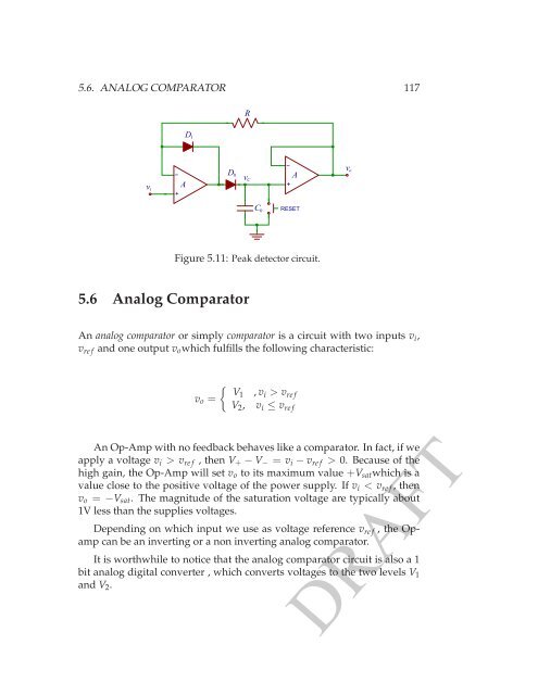
D 0<br />
v C<br />
v i<br />
A<br />
D 1<br />
R<br />
−<br />
+<br />
−<br />
+<br />
A<br />
v o<br />
C 0<br />
RESET<br />
Figure 5.11: Peak detector circuit.<br />
5.6 <strong>Analog</strong> Comparator<br />
An analog comparator or simply comparator is a circuit with two inputs v i ,<br />
v re f and one output v o which fulfills the following characteristic:<br />
{<br />
V1 , v<br />
v o =<br />
i > v re f<br />
V 2 , v i ≤ v re f<br />
An <strong>Op</strong>-<strong>Amp</strong> with no feedback behaves like a comparator. In fact, if we<br />
apply a voltage v i > v re f , then V + − V − = v i − v re f > 0. Because of the<br />
high gain, the <strong>Op</strong>-<strong>Amp</strong> will set v o to its maximum value +V sat which is a<br />
value close to the positive voltage of the power supply. If v i < v re f , then<br />
v o = −V sat . The magnitude of the saturation voltage are typically about<br />
1V less than the supplies voltages.<br />
Depending on which input we use as voltage reference v re f , the <strong>Op</strong>amp<br />
can be an inverting or a non inverting analog comparator.<br />
It is worthwhile to notice that the analog comparator circuit is also a 1<br />
bit analog digital converter , which converts voltages to the two levels V 1<br />
and V 2 .<br />
DRAFT