Analog Electronics Basic Op-Amp Applications - LIGO
Analog Electronics Basic Op-Amp Applications - LIGO
Analog Electronics Basic Op-Amp Applications - LIGO

Create successful ePaper yourself
Turn your PDF publications into a flip-book with our unique Google optimized e-Paper software.
112 CHAPTER 5. BASIC OP-AMP APPLICATIONS<br />
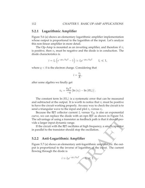
5.2.1 Logarithmic <strong>Amp</strong>lifier<br />
Figure 5.6 (a) shows an elementary logarithmic amplifier implementation<br />
whose output is proportional to the logarithm of the input. Let’s analyze<br />
this non-linear amplifier in more detail.<br />
The <strong>Op</strong>-<strong>Amp</strong> is mounted as an inverting amplifier, and therefore if v i<br />
is positive, then v o must be negative and the diode is in conduction. The<br />
diode characteristics is<br />
)<br />
i = I s<br />
(e −qv o/k B T − 1 ≃ I s e −qv o/k B T<br />
I s ≪ 1,<br />
where q < 0 is the electron charge. Considering that<br />
after some algebra we finally get<br />
i = v i<br />
R ,<br />
v o = k BT<br />
−q [ln(v i)−ln(RI s )] .<br />
The constant term ln(RI s ) is a systematic error that can be measured<br />
and subtracted at the output. It is worth to notice that v i must be positive<br />
to have the circuit working properly. An easy way to check the circuit is to<br />
send a triangular wave to the input and plot v o versus v i .<br />
Because the BJT collector current I c versus V BE is also an exponential<br />
curve, we can replace the diode with an npn BJT as shown in Figure 5.6.<br />
The advantage of using a transistor as feedback path is that it should provide<br />
a larger input dynamic range.<br />
If the circuit with the BJT oscillates at high frequency, a small capacitor<br />
in parallel to the transistor should stop the oscillation.<br />
5.2.2 Anti-Logarithmic <strong>Amp</strong>lifier<br />
Figure 5.7 (a) shows an elementary anti-logarithmic amplifier, i.e. the output<br />
is proportional to the inverse of logarithm of the input. The current<br />
flowing through the diode is<br />
i ≃ I s e −qv i/k B T<br />
I s ≪ 1.<br />
DRAFT