Analog Electronics Basic Op-Amp Applications - LIGO
Analog Electronics Basic Op-Amp Applications - LIGO
Analog Electronics Basic Op-Amp Applications - LIGO

You also want an ePaper? Increase the reach of your titles
YUMPU automatically turns print PDFs into web optimized ePapers that Google loves.
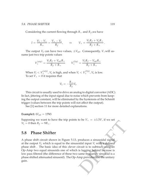
5.8. PHASE SHIFTER 119<br />
Considering the current flowing through R + and R f ,we have<br />
I = V 1− V +<br />
R +<br />
= V +− V o<br />
R f<br />
, ⇒ V + = V 1R f + V o R +<br />
R f + R +<br />
.<br />
The output V o can have two values, ±V sat . Consequently, V + will assume<br />
just two trip points values<br />
V (utp)<br />
+ = V 1R f + V sat R +<br />
R f + R +<br />
V (ltp)<br />
+ = V 1R f − V sat R +<br />
R f + R +<br />
When V i < V (utp)<br />
+ , V o is high, and when V i < V (ltp)<br />
+ , V o is low.<br />
To set V + = 0 it requires that<br />
V 1 = − R +<br />
R f<br />
V o<br />
This circuit is usually used to drive an analog to digital converter (ADC).<br />
In fact, jittering of the input signal due to noise which prevents from keeping<br />
the output constant, will be eliminated by the hysteresis of the Schmitt<br />
trigger (values between the trip points will not affect the output).<br />
See [1] section 11 for more detailed explanations.<br />
Example1: (V sat = 15V)<br />
Supposing we want to have the trip points to be V + = ±1.5V, if we set<br />
V 1 = 0 then R f = 9R + .<br />
5.8 Phase Shifter<br />
A phase shift circuit shown in Figure 5.13, produces a sinusoidal signal<br />
at the output V o which is equal to the sinusoidal input V i with a defined<br />
phase shift . The basic idea of this clever circuit is to subtract using an<br />
<strong>Op</strong>-<strong>Amp</strong> two equal sinusoids one of which is lagging behind because is<br />
low pass filtered (the difference of these two same frequency sinusoid is a<br />
phase shifted attenuated sinusoid). The <strong>Op</strong>-<strong>Amp</strong> provides also the unitary<br />
gain.<br />
DRAFT