Analog Electronics Basic Op-Amp Applications - LIGO
Analog Electronics Basic Op-Amp Applications - LIGO
Analog Electronics Basic Op-Amp Applications - LIGO

You also want an ePaper? Increase the reach of your titles
YUMPU automatically turns print PDFs into web optimized ePapers that Google loves.
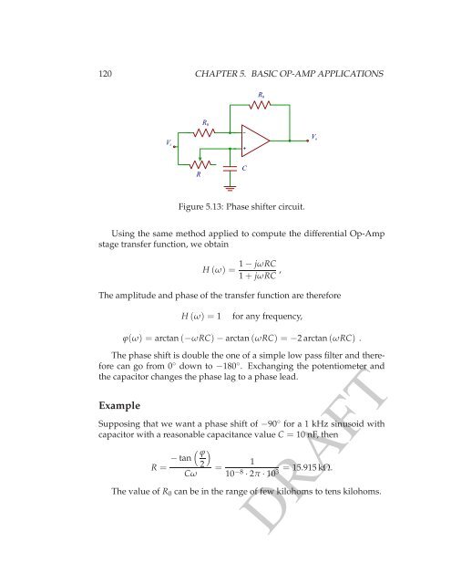
120 CHAPTER 5. BASIC OP-AMP APPLICATIONS<br />
V i<br />
R 0<br />
R 0<br />
−<br />
+<br />
V o<br />
R<br />
C<br />
Figure 5.13: Phase shifter circuit.<br />
Using the same method applied to compute the differential <strong>Op</strong>-<strong>Amp</strong><br />
stage transfer function, we obtain<br />
H(ω) =<br />
1− jωRC<br />
1+ jωRC ,<br />
The amplitude and phase of the transfer function are therefore<br />
H(ω) = 1<br />
for any frequency,<br />
ϕ(ω) = arctan(−ωRC)− arctan(ωRC) = −2 arctan(ωRC) .<br />
The phase shift is double the one of a simple low pass filter and therefore<br />
can go from 0 ◦ down to −180 ◦ . Exchanging the potentiometer and<br />
the capacitor changes the phase lag to a phase lead.<br />
Example<br />
Supposing that we want a phase shift of −90 ◦ for a 1 kHz sinusoid with<br />
capacitor with a reasonable capacitance value C = 10 nF, then<br />
R =<br />
( ϕ<br />
− tan<br />
2)<br />
Cω<br />
=<br />
1<br />
10 −8· = 15.915 kΩ.<br />
2π·103 The value of R 0 can be in the range of few kilohoms to tens kilohoms.<br />
DRAFT