Analog Electronics Basic Op-Amp Applications - LIGO
Analog Electronics Basic Op-Amp Applications - LIGO
Analog Electronics Basic Op-Amp Applications - LIGO

You also want an ePaper? Increase the reach of your titles
YUMPU automatically turns print PDFs into web optimized ePapers that Google loves.
5.10. PROBLEMS PREPARATORY TO THE LABORATORY 123<br />
5.10 Problems Preparatory to the Laboratory<br />
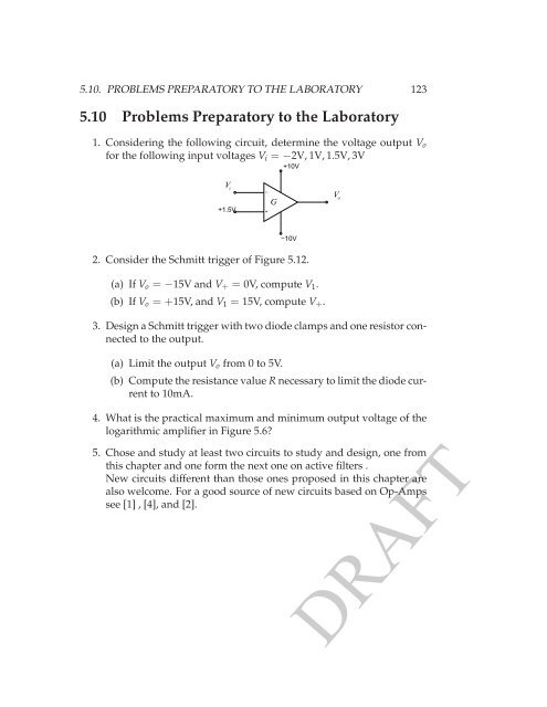
1. Considering the following circuit, determine the voltage output V o<br />
for the following input voltages V i = −2V, 1V, 1.5V, 3V<br />
+10V<br />
V i<br />
+1.5V<br />
−<br />
+<br />
G<br />
V o<br />
−10V<br />
2. Consider the Schmitt trigger of Figure 5.12.<br />
(a) If V o = −15V and V + = 0V, compute V 1 .<br />
(b) If V o = +15V, and V 1 = 15V, compute V + .<br />
3. Design a Schmitt trigger with two diode clamps and one resistor connected<br />
to the output.<br />
(a) Limit the output V o from 0 to 5V.<br />
(b) Compute the resistance value R necessary to limit the diode current<br />
to 10mA.<br />
4. What is the practical maximum and minimum output voltage of the<br />
logarithmic amplifier in Figure 5.6?<br />
5. Chose and study at least two circuits to study and design, one from<br />
this chapter and one form the next one on active filters .<br />
New circuits different than those ones proposed in this chapter are<br />
also welcome. For a good source of new circuits based on <strong>Op</strong>-<strong>Amp</strong>s<br />
see [1] , [4], and [2].<br />
DRAFT