Analog Electronics Basic Op-Amp Applications - LIGO
Analog Electronics Basic Op-Amp Applications - LIGO
Analog Electronics Basic Op-Amp Applications - LIGO

Create successful ePaper yourself
Turn your PDF publications into a flip-book with our unique Google optimized e-Paper software.
114 CHAPTER 5. BASIC OP-AMP APPLICATIONS<br />
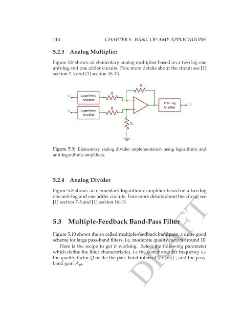
5.2.3 <strong>Analog</strong> Multiplier<br />
Figure 5.8 shows an elementary analog multiplier based on a two log one<br />
anti-log and one adder circuits. Fore more details about the circuit see [1]<br />
section 7-4 and [1] section 16-13.<br />
R<br />
v 1<br />
v 2<br />
Logarithmic<br />
<strong>Amp</strong>lifier<br />
Logarithmic<br />
<strong>Amp</strong>lifier<br />
R<br />
R<br />
−<br />
+<br />
Anti−Log<br />
<strong>Amp</strong>lifier<br />
v o<br />
R 0<br />
Figure 5.9: Elementary analog divider implementation using logarithmic and<br />
anti-logarithmic amplifiers.<br />
5.2.4 <strong>Analog</strong> Divider<br />
Figure 5.8 shows an elementary logarithmic amplifier based on a two log<br />
one anti-log and one adder circuits. Fore more details about the circuit see<br />
[1] section 7-5 and [1] section 16-13.<br />
5.3 Multiple-Feedback Band-Pass Filter<br />
Figure 5.10 shows the so called multiple-feedback bandpass, a quite good<br />
scheme for large pass-band filters, i.e. moderate quality factors around 10.<br />
Here is the recipe to get it working. Select the following parameter<br />
which define the filter characteristics, i.e the center angular frequency ω 0<br />
the quality factor Q or the the pass-band interval (ω 1 , ω 2 ) , and the passband<br />
gain A pb<br />
DRAFT