Analog Electronics Basic Op-Amp Applications - LIGO
Analog Electronics Basic Op-Amp Applications - LIGO
Analog Electronics Basic Op-Amp Applications - LIGO

You also want an ePaper? Increase the reach of your titles
YUMPU automatically turns print PDFs into web optimized ePapers that Google loves.
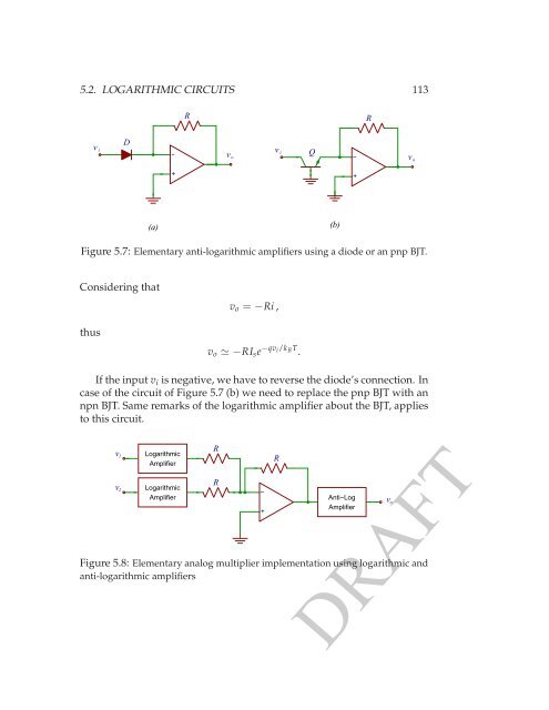
5.2. LOGARITHMIC CIRCUITS 113<br />
R<br />
R<br />
v<br />
i<br />
D<br />
−<br />
Q<br />
v<br />
v i<br />
o −<br />
v o<br />
+<br />
+<br />
(a)<br />
(b)<br />
Figure 5.7: Elementary anti-logarithmic amplifiers using a diode or an pnp BJT.<br />
Considering that<br />
thus<br />
v o = −Ri ,<br />
v o ≃ −RI s e −qv i/k B T .<br />
If the input v i is negative, we have to reverse the diode’s connection. In<br />
case of the circuit of Figure 5.7 (b) we need to replace the pnp BJT with an<br />
npn BJT. Same remarks of the logarithmic amplifier about the BJT, applies<br />
to this circuit.<br />
v 1<br />
v 2<br />
Logarithmic<br />
<strong>Amp</strong>lifier<br />
Logarithmic<br />
<strong>Amp</strong>lifier<br />
R<br />
R<br />
−<br />
+<br />
Anti−Log<br />
<strong>Amp</strong>lifier<br />
Figure 5.8: Elementary analog multiplier implementation using logarithmic and<br />
anti-logarithmic amplifiers<br />
R<br />
v o<br />
DRAFT