paper - Odeon
paper - Odeon
paper - Odeon

You also want an ePaper? Increase the reach of your titles
YUMPU automatically turns print PDFs into web optimized ePapers that Google loves.
SPL(dB)<br />
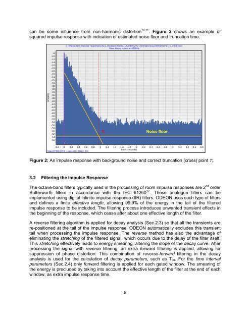
can be some influence from non-harmonic distortion 10,11 . Figure 2 shows an example of<br />
squared impulse response with indication of estimated noise floor and truncation time.<br />
D:\Measured Impulse responses\isra_measurements1\Auditorium21GEorgeClaus15feb2013\s1r1_4000.wav<br />
Raw decay curve at 4000Hz<br />
-8<br />
-10<br />
-12<br />
-14<br />
-16<br />
-18<br />
-20<br />
-22<br />
-24<br />
-26<br />
-28<br />
-30<br />
-32<br />
-34<br />
-36<br />
-38<br />
-40<br />
-42<br />
-44<br />
-46<br />
-48<br />
-50<br />
-52<br />
-54<br />
-56<br />
-58<br />
-60<br />
-62<br />
-64<br />
-66<br />
T t<br />
Noise floor<br />
gfedcb<br />
gfedcb<br />
gfedcb<br />
gfedcb<br />
E, Measured<br />
Noise floor<br />
Onset time<br />
Truncation time<br />
-0.2 0 0.2 0.4 0.6<br />
<strong>Odeon</strong>©1985-2013 Licensed to: <strong>Odeon</strong> A/S<br />
0.8<br />
1<br />
1.2<br />
1.4<br />
1.6 1.8 2<br />
time (seconds)<br />
2.2<br />
2.4<br />
2.6<br />
2.8<br />
3<br />
3.2<br />
3.4<br />
3.6<br />
3.8<br />
Figure 2: An impulse response with background noise and correct truncation (cross) point T t.<br />
3.2 Filtering the Impulse Response<br />
The octave-band filters typically used in the processing of room impulse responses are 2 nd order<br />
Butterworth filters in accordance with the IEC 61260 12 . These analogue filters can be<br />
implemented using digital infinite impulse response (IIR) filters. ODEON uses such type of filters<br />
and defines a finite effective length, allowing 99.9% of the energy in the tail of the filtered<br />
impulse response to be included. The filtering process introduces unwanted transient effects in<br />
the beginning of the response, which cease after about one effective length of the filter.<br />
A reverse filtering algorithm is applied for decay analysis (Sec.2.3) so that all the transients are<br />
re-positioned at the tail of the impulse response. ODEON automatically excludes this transient<br />
tail when processing the impulse response. The reverse method has also the advantage of<br />
eliminating the stretching of the filtered signal, which occurs due to the delay of the filter itself.<br />
This stretching effectively leads to energy smearing, altering the slope of the decay curve. After<br />
processing the signal with reverse filtering, an extra forward filtering is applied, allowing for<br />
suppression of phase distortion. This combination of reverse-forward filtering in the decay<br />
analysis is used for the calculation of decay parameters, such as T 30 . For the time interval<br />
parameters (Sec.2.4) only forward filtering is applied for each gated window. The smearing of<br />
the energy is precluded by taking into account the effective length of the filter at the end of each<br />
window, as extra impulse response time.<br />
9