LAC-1 single axis controller manual
LAC-1 single axis controller manual
LAC-1 single axis controller manual

Create successful ePaper yourself
Turn your PDF publications into a flip-book with our unique Google optimized e-Paper software.
SMAC<br />
<strong>LAC</strong>-1 Technical Reference Manual<br />
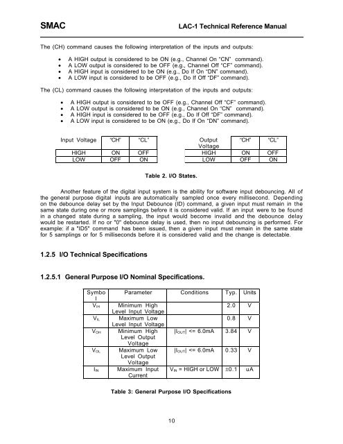
The (CH) command causes the following interpretation of the inputs and outputs:<br />
• A HIGH output is considered to be ON (e.g., Channel On ÒCNÓ command).<br />
• A LOW output is considered to be OFF (e.g., Channel Off ÒCFÓ command).<br />
• A HIGH input is considered to be ON (e.g., Do If On ÒDNÓ command).<br />
• A LOW input is considered to be OFF (e.g., Do If Off ÒDFÓ command).<br />
The (CL) command causes the following interpretation of the inputs and outputs:<br />
• A HIGH output is considered to be OFF (e.g., Channel Off ÒCFÓ command).<br />
• A LOW output is considered to be ON (e.g., Channel On ÒCNÓ command).<br />
• A HIGH input is considered to be OFF (e.g., Do If Off ÒDFÓ command).<br />
• A LOW input is considered to be ON (e.g., Do If On ÒDNÓ command).<br />
Input Voltage ÒCHÓ ÒCLÓ Output ÒCHÓ ÒCLÓ<br />
Voltage<br />
HIGH ON OFF HIGH ON OFF<br />
LOW OFF ON LOW OFF ON<br />
Table 2. I/O States.<br />
Another feature of the digital input system is the ability for software input debouncing. All of<br />
the general purpose digital inputs are automatically sampled once every millisecond. Depending<br />
on the debounce delay set by the Input Debounce (ID) command, a given input must remain in the<br />
same state during one or more samplings before it is considered valid. If an input were to be found<br />
in a changed state during a sampling, the input would become invalid and the debounce delay<br />
would be restarted. If no or "0" debounce delay is used, then no input debouncing is performed. For<br />
example: if a "ID5" command has been issued, then a given input must remain in the same state<br />
for 5 samplings or for 5 milliseconds before it is considered valid and the change is detectable.<br />
1.2.5 I/O Technical Specifications<br />
1.2.5.1 General Purpose I/O Nominal Specifications.<br />
Symbo<br />
l<br />
V IH<br />
V IL<br />
V OH<br />
V OL<br />
I IN<br />
Parameter Conditions Typ. Units<br />
Minimum High<br />
Level Input Voltage<br />
Maximum Low<br />
Level Input Voltage<br />
Minimum High<br />
Level Output<br />
Voltage<br />
Maximum Low<br />
Level Output<br />
Voltage<br />
Maximum Input<br />
Current<br />
2.0 V<br />
0.8 V<br />
|I OUT |