LAC-1 single axis controller manual
LAC-1 single axis controller manual
LAC-1 single axis controller manual

Create successful ePaper yourself
Turn your PDF publications into a flip-book with our unique Google optimized e-Paper software.
SMAC<br />
<strong>LAC</strong>-1 Technical Reference Manual<br />
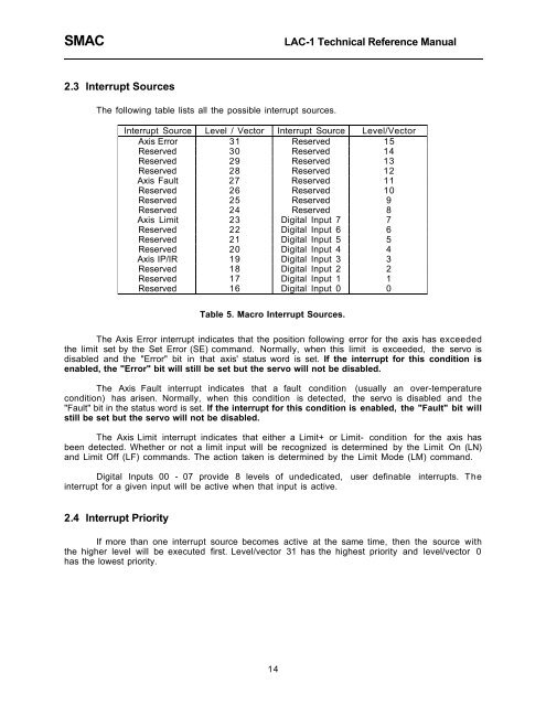
2.3 Interrupt Sources<br />
The following table lists all the possible interrupt sources.<br />
Interrupt Source Level / Vector Interrupt Source Level/Vector<br />
Axis Error 31 Reserved 15<br />
Reserved 30 Reserved 14<br />
Reserved 29 Reserved 13<br />
Reserved 28 Reserved 12<br />
Axis Fault 27 Reserved 11<br />
Reserved 26 Reserved 10<br />
Reserved 25 Reserved 9<br />
Reserved 24 Reserved 8<br />
Axis Limit 23 Digital Input 7 7<br />
Reserved 22 Digital Input 6 6<br />
Reserved 21 Digital Input 5 5<br />
Reserved 20 Digital Input 4 4<br />
Axis IP/IR 19 Digital Input 3 3<br />
Reserved 18 Digital Input 2 2<br />
Reserved 17 Digital Input 1 1<br />
Reserved 16 Digital Input 0 0<br />
Table 5. Macro Interrupt Sources.<br />
The Axis Error interrupt indicates that the position following error for the <strong>axis</strong> has exceeded<br />
the limit set by the Set Error (SE) command. Normally, when this limit is exceeded, the servo is<br />
disabled and the "Error" bit in that <strong>axis</strong>' status word is set. If the interrupt for this condition is<br />
enabled, the "Error" bit will still be set but the servo will not be disabled.<br />
The Axis Fault interrupt indicates that a fault condition (usually an over-temperature<br />
condition) has arisen. Normally, when this condition is detected, the servo is disabled and the<br />
"Fault" bit in the status word is set. If the interrupt for this condition is enabled, the "Fault" bit will<br />
still be set but the servo will not be disabled.<br />
The Axis Limit interrupt indicates that either a Limit+ or Limit- condition for the <strong>axis</strong> has<br />
been detected. Whether or not a limit input will be recognized is determined by the Limit On (LN)<br />
and Limit Off (LF) commands. The action taken is determined by the Limit Mode (LM) command.<br />
Digital Inputs 00 - 07 provide 8 levels of undedicated, user definable interrupts. The<br />
interrupt for a given input will be active when that input is active.<br />
2.4 Interrupt Priority<br />
If more than one interrupt source becomes active at the same time, then the source with<br />
the higher level will be executed first. Level/vector 31 has the highest priority and level/vector 0<br />
has the lowest priority.<br />
14