LAC-1 single axis controller manual
LAC-1 single axis controller manual
LAC-1 single axis controller manual

You also want an ePaper? Increase the reach of your titles
YUMPU automatically turns print PDFs into web optimized ePapers that Google loves.
SMAC<br />
<strong>LAC</strong>-1 Technical Reference Manual<br />
1.2 Digital I/O Interface<br />
The <strong>LAC</strong>-1 includes 8 channels of HCT TTL general purpose digital input and 8 channels<br />
of HCT TTL general purpose digital output. Additionally, there are four channels of TTL dedicated<br />
digital input. The general purpose I/O are buffered with 74HCT541. An expansion interface allows<br />
for optional expansion of I/O to 64 channels.<br />
1.2.1 Dedicated Digital Inputs<br />
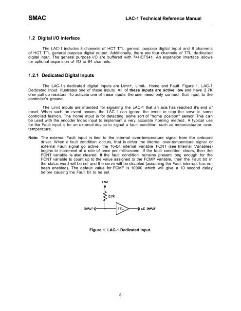
The <strong>LAC</strong>-1Õs dedicated digital inputs are Limit+, Limit-, Home and Fault. Figure 1. <strong>LAC</strong>-1<br />
Dedicated Input. illustrates one of these inputs. All of these inputs are active low and have 2.7K<br />
ohm pull up resistors. To activate one of these inputs, the user need only connect that input to the<br />
<strong>controller</strong>Õs ground.<br />
The Limit inputs are intended for signaling the <strong>LAC</strong>-1 that an <strong>axis</strong> has reached itÕs end of<br />
travel. When such an event occurs, the <strong>LAC</strong>-1 can ignore the event or stop the servo in some<br />
controlled fashion. The Home input is for detecting some sort of "home position" sensor. This can<br />
be used with the encoder Index input to implement a very accurate homing method. A typical use<br />
for the Fault input is for an external device to signal a fault condition such as motor/actuator overtemperature.<br />
Note: The external Fault input is tied to the internal over-temperature signal from the onboard<br />
driver. When a fault condition occurs, that is either the internal over-temperature signal or<br />
external Fault signal go active, the 16-bit internal variable FCNT (see Internal Variables)<br />
begins to increment at a rate of once per millisecond. If the fault condition clears, then the<br />
FCNT variable is also cleared. If the fault condition remains present long enough for the<br />
FCNT variable to count up to the value assigned to the FCMP variable, then the Fault bit in<br />
the status word will be set and the servo will be disabled (assuming the Fault interrupt has not<br />
been enabled). The default value for FCMP is 10000 which will give a 10 second delay<br />
before causing the Fault bit to be set.<br />
Figure 1. <strong>LAC</strong>-1 Dedicated Input.<br />
8