LAC-1 single axis controller manual
LAC-1 single axis controller manual
LAC-1 single axis controller manual

You also want an ePaper? Increase the reach of your titles
YUMPU automatically turns print PDFs into web optimized ePapers that Google loves.
SMAC<br />
<strong>LAC</strong>-1 Technical Reference Manual<br />
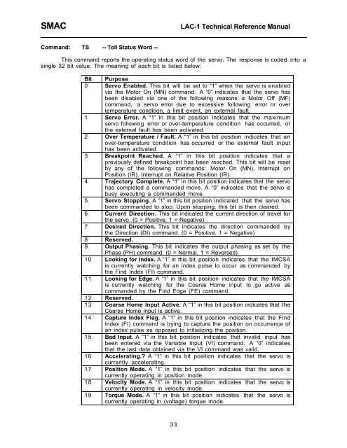
Command: TS -- Tell Status Word --<br />
This command reports the operating status word of the servo. The response is coded into a<br />
<strong>single</strong> 32 bit value. The meaning of each bit is listed below:<br />
Bit Purpose<br />
0 Servo Enabled. This bit will be set to Ò1Ó when the servo is enabled<br />
via the Motor On (MN) command. A Ò0Ó indicates that the servo has<br />
been disabled via one of the following reasons: a Motor Off (MF)<br />
command, a servo error due to excessive following error or over<br />
temperature condition, a limit event, an external fault.<br />
1 Servo Error. A Ò1Ó in this bit position indicates that the maximum<br />
servo following error or over-temperature condition has occurred, or<br />
the external fault has been activated.<br />
2 Over Temperature / Fault. A Ò1Ó in this bit position indicates that an<br />
over-temperature condition has occurred or the external fault input<br />
has been activated.<br />
3 Breakpoint Reached. A Ò1Ó in this bit position indicates that a<br />
previously defined breakpoint has been reached. This bit will be reset<br />
by any of the following commands: Motor On (MN), Interrupt on<br />
Position (IR), Interrupt on Relative Position (IR).<br />
4 Trajectory Complete. A Ò1Ó in this bit position indicates that the servo<br />
has completed a commanded move. A Ò0Ó indicates that the servo is<br />
busy executing a commanded move.<br />
5 Servo Stopping. A Ò1Ó in this bit position indicated that the servo has<br />
been commanded to stop. Upon stopping, this bit is then cleared.<br />
6 Current Direction. This bit indicated the current direction of travel for<br />
the servo. (0 = Positive, 1 = Negative)<br />
7 Desired Direction. This bit indicates the direction commanded by<br />
the Direction (DI) command. (0 = Positive, 1 = Negative)<br />
8 Reserved.<br />
9 Output Phasing. This bit indicates the output phasing as set by the<br />
Phase (PH) command. (0 = Normal, 1 = Reversed)<br />
10 Looking for Index. A Ò1Ó in this bit position indicates that the IMCSA<br />
is currently watching for an index pulse to occur as commanded by<br />
the Find Index (FI) command.<br />
11 Looking for Edge. A Ò1Ó in this bit position indicates that the IMCSA<br />
is currently watching for the Coarse Home input to go active as<br />
commanded by the Find Edge (FE) command.<br />
12 Reserved.<br />
13 Coarse Home Input Active. A Ò1Ó in this bit position indicates that the<br />
Coarse Home input is active.<br />
14 Capture Index Flag. A Ò1Ó in this bit position indicates that the Find<br />
Index (FI) command is trying to capture the position on occurrence of<br />
an index pulse as opposed to initializing the position.<br />
15 Bad Input. A Ò1Ó in this bit position indicates that invalid input has<br />
been entered via the Variable Input (VI) command. A Ò0Ó indicates<br />
that the last data obtained via the VI command was valid.<br />
16 Accelerating.? A Ò1Ó in this bit position indicates that the servo is<br />
currently accelerating.<br />
17 Position Mode. A Ò1Ó in this bit position indicates that the servo is<br />
currently operating in position mode.<br />
18 Velocity Mode. A Ò1Ó in this bit position indicates that the servo is<br />
currently operating in velocity mode.<br />
19 Torque Mode. A Ò1Ó in this bit position indicates that the servo is<br />
currently operating in (voltage) torque mode.<br />
33