
You also want an ePaper? Increase the reach of your titles
YUMPU automatically turns print PDFs into web optimized ePapers that Google loves.
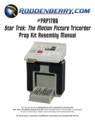
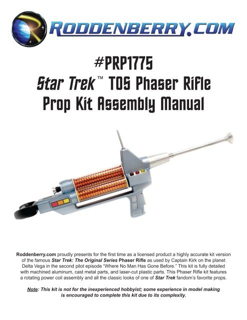
#PRP1775<br />
<strong>Star</strong> <strong>Trek</strong> TOS Phaser Rifle<br />
Prop Kit Assembly Manual<br />
<strong>Roddenberry</strong>.<strong>com</strong> proudly presents for the first time as a licensed product a highly accurate kit version<br />
of the famous <strong>Star</strong> <strong>Trek</strong>: The Original Series Phaser Rifle as used by Captain Kirk on the planet<br />
Delta Vega in the second pilot episode “Where No Man Has Gone Before.” This kit is fully detailed<br />
with machined aluminum, cast metal parts, and laser-cut plastic parts. This Phaser Rifle kit features<br />
a rotating power coil assembly and all the classic looks of one of <strong>Star</strong> <strong>Trek</strong> fandom’s favorite props.<br />
Note: This kit is not for the inexperienced hobbyist; some experience in model making<br />
is encouraged to <strong>com</strong>plete this kit due to its <strong>com</strong>plexity.
2<br />
#PRP1775 - St a r Tr e k: TOS Ph a s e r Rifle Pr o p Kit As s e m b l y Ma n u a l<br />
Tools And Supplies Needed:<br />
• Auto body spot putty, and/or Bondo filler<br />
• Sandpaper (220 rough grit, 320, 400, up to 600 finish grits)<br />
• Dremel tool<br />
• Hand drill<br />
• 3/32 -inch drill bit<br />
• 1/16 -inch drill bit<br />
• 1/8 -inch drill bit<br />
• Hobby knife (X-Acto brand or similar)<br />
• 5-minute epoxy glue<br />
• Cyanoacrylate Glue<br />
• Testors Clear Parts Cement<br />
• Masking tape (blue low-tack painter’s tape re<strong>com</strong>mended)<br />
• An assistant for certain 2-person assembly operations (re<strong>com</strong>mended)<br />
Paint Options:<br />
• Sandable-type gray primer (Undercoat)<br />
• Plastikote 1540 Light Blue Truck Paint (Main Body)<br />
• Krylon Dull Aluminum or silver (Barrel Base)<br />
• Krylon Metallic Copper (Power Coil Cores)<br />
• Krylon Semi-Flat Black (Handgrip)<br />
• Brush-on gold (Barrel Fins)
Parts Prep<br />
#PRP1775 - St a r Tr e k: TOS Ph a s e r Rifle Pr o p Kit As s e m b l y Ma n u a l 3<br />
Step 1: Wash your resin castings with a chlorine-based soap such as Ajax or Comet along with water to<br />
remove any trace of mold release. Rinse thoroughly and let dry.<br />
Sand all mold lines, flashing, and sprues from the resin and unfinished cast metal parts as well as the<br />
bottoms of the six-colored core end rings and the three indicators until smooth, and bondo and putty any<br />
objectionable holes or lines in the resin parts. Some holes may already be filled by the manufacturer before<br />
shipping.<br />
Any parts that fit into other parts may need to be sanded for proper fit. And with the exception of the rear<br />
body to the handgrip bridge, drill your holes before painting. Check and recheck the fit of all parts before<br />
painting or permanently assembling anything. There isn’t a set procedure for drilling and finishing your<br />
parts and making your sub-assemblies, but there is a definite assembly procedure for putting the main rifle<br />
pieces together. Taking your time with this project will yield a prop you’ll be proud of!<br />
Sand and use the Scotchbrite pad on the trigger and the cast metal side indicator and slotted plates for<br />
a brushed metal finish. You may also use the Scotchbrite on the aluminum barrel tube if desired. Drill the<br />
mounting holes on the two plates with up to a 3/32” bit, and clean up the countersinks so the 2-56 screws<br />
will be flat with the surface.<br />
The machined metal parts should not require any further finishing work.<br />
Any acrylic parts you will be gluing to acrylic are best glued with acrylic or styrene solvent cement to “weld”<br />
the parts together. And when securing to resin or metal, use 5-minute epoxy, or a “window builder” glue like<br />
Testors Clear Parts Cement if gluing something that will be visible, like the rear side windows. Avoid using<br />
cyanoacrylate glues on visible acrylic details, they may white-fog and craze acrylic plastics.
4<br />
#PRP1775 - St a r Tr e k: TOS Ph a s e r Rifle Pr o p Kit As s e m b l y Ma n u a l<br />
Front Body and Handgrip Bridge Assembly<br />
Bullet catches and power coil bushings, showing the approximate height of the bullet above the bushing surface.<br />
Step 2: Test fit the bullet catches on the two body parts, roughen the resin surface where the bushings<br />
will be glued, then glue on the two power coil bushings with CA glue, being sure they’re centered on each<br />
bullet catch and on the center axle hole. Sand the bushings so they’re smooth, and before painting the<br />
body parts, mask the bushings – you don’t need to have paint rubbing off and possibly gumming the works<br />
when you’re rotating the power coil, and it also serves to mask the axle holes. You may glue the catches at<br />
this time or wait until after painting – see later in the instructions for gluing details.<br />
Step 3: Drill 1/16” holes for securing the front body indicator and slotted plates (slot plate on left, the 3-hole<br />
plate on right when facing forward with the part as if you’re holding it to fire at a target). You can try to<br />
thread the 2-56 screws in the resin...or if you can, buy a 2-56 tap (available at many hobby or hardware<br />
stores).
#PRP1775 - St a r Tr e k: TOS Ph a s e r Rifle Pr o p Kit As s e m b l y Ma n u a l 5<br />
Styrene pieces in bridge resin, and front body to handgrip bridge assembly.<br />
Step 4: The handgrip bridge has several pieces of white plastic that are visible and/or sticking out of the<br />
casting. These are put on during the casting process to suspend two metal stiffening rods and should be<br />
sanded or ground away with a Dremel tool below the part surface, then bondo filled and sanded smooth.<br />
If they are merely sanded flush, they might show up later after painting as all cast resin parts shrink a little<br />
over time.<br />
The front body should be secured to the handgrip bridge before painting. It will save from having to<br />
manhandle the parts too much from going through the placement and drilling process after painting with the<br />
risk of damaging the paint finish. When placed at its desired spot with the front edges of bridge and body<br />
flush to each other, use a T-square or other 90º square tool or object and square the back side with the<br />
length of the handgrip bridge and mark and drill into the front body with your 1/8” drill for the 2 1/2” screws.<br />
It is highly re<strong>com</strong>mended that you pre-screw in these two holes with the screws (just like using a tap for<br />
threading holes for machine screws) before you actually attach the parts, just in case you’re having a hard<br />
time getting them in – it is possible for the screws to break before they go in all the way. You may fill in the<br />
screw heads, if desired, for a smooth finish, or leave them alone, as this is accurate to the film-used prop.<br />
CA glue may also be used in the joint, if you want, after screwing it together for greater strength.<br />
Important Note: The rear body cannot be marked or drilled until after the prop is painted and the<br />
rotating power coil is fully assembled with the bullet catches in place on the two body parts.
6<br />
#PRP1775 - St a r Tr e k: TOS Ph a s e r Rifle Pr o p Kit As s e m b l y Ma n u a l<br />
PAINTING<br />
Masking and final paint finish of handgrip.<br />
Step 5: Mask those areas that will be glued to each other or that need to be free of paint – if they’re not<br />
masked, they’ll need to have the paint scraped, as glue does not stick to paint very well. Spray a primer<br />
coat first, fill in and sand holes and flaws that you missed, then primer again.<br />
When the primer finish of your parts is good, spray in metallic blue the front body/handgrip bridge<br />
assembly, and the rear body.<br />
If you look at the episode and/or look at screen captures of the rifle, it appears the recesses in the handgrip<br />
might have been painted silver. It is entirely a personal preference if you want to paint the grip recesses<br />
silver or not, but if you do, paint the silver contrast color after you paint the finish blue coat...and be sure<br />
you cover everything you don’t want silver overspray on. It can be a pain to clean up from an already<br />
finished surface.<br />
Step 6: Spray in silver the resin barrel, and brush paint with gold or brass the 12 ribs in the front end. You<br />
may paint inside this area with black to make the gold stand out better if desired, either with brush paint or<br />
with spray paint as part of the silver painting process before you apply the gold.
#PRP1775 - St a r Tr e k: TOS Ph a s e r Rifle Pr o p Kit As s e m b l y Ma n u a l 7<br />
Spraying and masking the rear body contrast colors.<br />
Step 7: Spray in semi-flat black the slightly inset large square detail on the top of the rear body and the<br />
circle on the back of the round cylinder that the eyecup screws onto (mask the blue first, or spray black first<br />
and mask the square and the circle before spraying blue – regardless of the order of painting, allow several<br />
hours or overnight for your first color to cure before applying any masking tape).<br />
Rear handle, and eyecup masking before spraying the exposed metal black.<br />
Step 8: Also primer and spray semi-flat black the rear handle (mask the threaded stud) and the eyecup<br />
body but not the flared flange (see masking in photo).
8<br />
#PRP1775 - St a r Tr e k: TOS Ph a s e r Rifle Pr o p Kit As s e m b l y Ma n u a l<br />
Sample paint photo left to right: Tamiya custom mix on raw metal as used on the instruction pictures,<br />
raw aluminum, and Krylon Metallic Copper on primer<br />
Step 9: The machined aluminum power coil cores are finished in copper; they may be painted with primer<br />
then Krylon Metallic Copper or a similar copper paint, which is the most economical method without<br />
purchasing an airbrush or sending them to a plating or anodizing shop. While dull looking, it does make it<br />
look a little more like “used” or “oxidized” copper.<br />
Before painting using your chosen method, clean any residual oils off the cores with a solvent or with soap<br />
and water, let dry before painting.<br />
HMS Creative Productions painting expert Darcienne Sparber suggests that if you want to make the copper<br />
look more like shiny new metal and you have access to an airbrush (expert airbrush use not required), you<br />
can airbrush directly on the metal -- no primer needed! You will need to create a custom mix of transparent<br />
red and orange with Tamiya brand jar paints re<strong>com</strong>mended (approx. 60-70 percent transparent red with the<br />
rest transparent orange) to create a plated-looking metal finish. Add a few drops of transparent green to<br />
the mix to cut down on the screaming orange glare – copper metal does have a little bit of a greenish tone.<br />
Airbrush one or more thin coats on the cores, and you’ll be amazed at how well they’ll look. And if for some<br />
reason the color or the finish isn’t quite to your liking, you can easily strip Tamiya paints from the cores<br />
using denatured alcohol, acetone, or some other solvent and try again. Test spray a small portion of one<br />
core or a scrap piece of aluminum before <strong>com</strong>mitting all of the cores to paint if necessary.<br />
Another method you may decide to use for the power coil cores is airbrushing Alclad brand paint (copper),<br />
but wey re<strong>com</strong>mend the part be painted gloss black first for all their paints. It is too thin to be sprayed<br />
directly on metal and have it darken enough for the desired look – but you will have a convincing-looking<br />
copper power core.<br />
One other method you can use is copper anodizing or plating, but this be<strong>com</strong>es expensive and is<br />
impractical for most people.
#PRP1775 - St a r Tr e k: TOS Ph a s e r Rifle Pr o p Kit As s e m b l y Ma n u a l 9<br />
Power Coil End plates<br />
Step 10: Assemble the two power coil end plates as follows: remove the paper from all plastic parts, then<br />
insert the 3/16” brass alignment pin into the center hole and place one of the axles on this. With acrylic<br />
solvent cement, glue the axle in place, making sure you have a solid glue joint without any voids. Allow the<br />
joint to harden up a few minutes, then you can remove the pin and repeat the process for the other end<br />
plate. The glue pictured above is fairly thick, but will work as long as you allow it to cure to its maximum<br />
strength – don’t play with the parts while the glue is doing its work! Pressing down and slightly rotating<br />
the parts will help in “welding” the joints.<br />
On the opposite side of the plate from the axle, use the 1/8” pin to align and glue each of the three inner<br />
core alignment plates onto the end plate, again allowing a little time before you remove the pin, as there<br />
might be a danger of the part shifting on you if the joint is still fresh. Do not put these plates on the same<br />
side as the axle; the part will not work and will be almost irreparable if you do.
10<br />
#PRP1775 - St a r Tr e k: TOS Ph a s e r Rifle Pr o p Kit As s e m b l y Ma n u a l<br />
Power Coils<br />
Power coil parts before assembly.<br />
All-thread rod in one of the end plates, and sanding the bottom of the core end rings.<br />
Step 11: Have your 8-32 all-thread rod ready with one end having a nut and washer and through an end<br />
plate.<br />
If you haven’t done it before now, sand the bottoms of the colored core end rings and remove any flashing<br />
from them, making sure they fit in the clear tubes.<br />
Clean the three clear tubes using a plastic cleaner, preferably one that will make the plastic anti-static, and<br />
try to keep dust out of the tubes and off the copper finished cores when you’re assembling.
#PRP1775 - St a r Tr e k: TOS Ph a s e r Rifle Pr o p Kit As s e m b l y Ma n u a l 11<br />
Assembly of power coil.<br />
Step 12: Assemble the power coil by laying down on a table one of the end plates with the all-thread<br />
sticking upwards, and putting in place the cores and clear tubes, along with the colored core end rings.<br />
Don’t try to push a core end ring through the length of tube – work one core at a time, and make sure the<br />
same color is on the same core. You might want the assistance of a friend for this assembly.<br />
Any imperfections in any of the parts can be rotated to the inside so they won’t be as obviously visible on<br />
the finished prop. If done properly, gluing is not necessary for any of these parts.
12<br />
#PRP1775 - St a r Tr e k: TOS Ph a s e r Rifle Pr o p Kit As s e m b l y Ma n u a l<br />
Step 13: When the other end plate is secured, get a washer and nut on the all-thread to keep it together.<br />
When properly tightened and straight (try not to stress the acrylic end plates by overtightening, but be sure<br />
the assembly isn’t loose; gently twist the assembly to check for looseness), use the other two nuts and<br />
tighten against the first two nuts to keep everything secured and prevent the assembly from working itself<br />
loose.
Final Assembly<br />
#PRP1775 - St a r Tr e k: TOS Ph a s e r Rifle Pr o p Kit As s e m b l y Ma n u a l 13<br />
Gluing front grill to the black square background.<br />
Step 14: The clear grill portion should be painted silver, either with a brush after gluing, or use spray paint<br />
while it is still separate from the background piece. You can leave the grill clear if you want, but when glued<br />
onto the black background square, it might not look as good or show up as well. Sand the bottom side of<br />
the grill detail (and not the black background) to get rid of residual paint, then glue the grill onto the black<br />
square with solvent cement at the corners and/or edges. Use just enough for a good joint and allow to cure.<br />
You might need to sand the edges of the assembled grill before it will fit into the body recess.<br />
Step 15: Before (or after) painting, glue on the two bullet catches with 5-minute epoxy, making real sure<br />
you don’t glue the interior springs of the catches or the moving bullet core itself – these allow the power coil<br />
assembly to “lock in place” at the desired settings with an audible click. You won’t have a second chance if<br />
you use too much glue to where it gums up the works – you only need a little glue on one side of the hole.<br />
The bullet catches may be pressed in without glue if the hole is tight enough for it to stay in place. When<br />
correctly installed, the lip of the catch body will be below the surface of the bushing plate (see the pictures<br />
earlier in the instructions), with the bullet end sticking out so they will engage the end plate holes. When<br />
you’re making the final assembly of your rifle, you can use a small drop of oil in the bullet catch to make the<br />
spring-action a little easier.
14<br />
#PRP1775 - St a r Tr e k: TOS Ph a s e r Rifle Pr o p Kit As s e m b l y Ma n u a l<br />
Trigger orientation to grip.<br />
Step 16: Stick the foam strip to the back edge of the trigger near the round end – it is a self-stick strip, but<br />
you may use CA if needed. The trigger is secured by the 4-40 set screw from the right side and will capture<br />
the trigger. While it will hang loose, it shouldn’t swing wildly out the front.<br />
Front grill and resin barrel base on rifle.<br />
Step 17: After painting, glue the <strong>com</strong>pleted front grill into the square depression below the barrel by scraping<br />
paint away from the raised middle and using epoxy glue (glue does not stick well to painted surfaces). Glue<br />
the painted resin barrel base in place with CA glue or 5-minute epoxy before (or after) assembling the power<br />
coil and the rear body to the main rifle. You’ll want to align the ribs so they appear even with the body. Test<br />
fit this part first before gluing! Do not glue the aluminum barrel tube at this time, though you can glue the<br />
emitter dish and tip as a sub-assembly...but without gluing the dish to the barrel tube.<br />
Step 18: Install the antenna to the top of the front body, rounded end up. You may need to get a 5/16” drill<br />
bit and a drill to loosen the hole slightly, as well as possibly having to angle the hole if the antenna doesn’t sit<br />
straight on the body – check antenna fit before drilling anything. Once the antenna is glued using 5-minute<br />
epoxy sparingly on one side of the hole (using too much glue may create an air seal which will make it very<br />
difficult to push the antenna in), slip on and epoxy glue the antenna collar in place. You may want to sand the<br />
bottom surface of the collar flat before installing.
#PRP1775 - St a r Tr e k: TOS Ph a s e r Rifle Pr o p Kit As s e m b l y Ma n u a l 15<br />
Step 19: Carefully cut out and apply the self-stick target sight graphic onto the square white/milk plex<br />
piece, then glue to the front body with epoxy glue (scrape away the paint in the middle first!).<br />
Step 20: Screw the indicator plate to the right side, then glue the three round indicators into the holes of<br />
the indicator plate (back to front: red, orange, yellow). Apply the strip of black vinyl tape in the left side<br />
depression – it should reach from end to end in the depression, and then screw the slotted plate on.<br />
The photo on the right shows clearly the sight and two side panels of the Front Body in their finished form.<br />
Vinyl, graphics, and plates and details are installed.<br />
Step 21: Cut out the two side indicator graphics and fit these in the side depressions as shown (red to<br />
the back, and be sure it fully fits without it buckling when the window is put in). Then, after peeling the<br />
protective paper from the side windows, put these in place one at a time and glue using Testors Clear Parts<br />
Cement & Window Maker without scraping the paint – and try to avoid getting glue inside the window,<br />
which may damage the graphic. If desired, you may want to brush paint some black along the inside edges<br />
just in case you cut away any of the black border on the graphic sheets before gluing. Follow the directions<br />
on the glue; it may take an hour or two before the joint is secure enough for you to glue the other side.
16<br />
#PRP1775 - St a r Tr e k: TOS Ph a s e r Rifle Pr o p Kit As s e m b l y Ma n u a l<br />
Screwing in eyecup, and finished with eyecup dot in place.<br />
Step 22: On the rear body, secure the eyecup and tube on the back of the round resin area with the 1 1/2”<br />
screw (pre-screw the hole first!), then hide the screw by gluing on the black plastic dot with CA or epoxy.<br />
Drilling and screwing on the rear body to the rifle.<br />
Step 23: Now that you have your parts painted, your power coil assembled, and the front body in place<br />
with both bullet catches installed; you may now place and secure the rear body, which is done by holding<br />
the power coil and the rear body together on the handgrip bridge and pushing together on the front body as<br />
straight as possible (remember you have two bullet catches that may be pushing the parts away from each<br />
other, and you want all of the parts to be tight). Secure the use of the previously-mentioned friend if needed<br />
(which is mentioned in the tool list – get one at least!) and mark the location of the two screw holes. Then<br />
set everything else aside and drill the two 1/8” holes in the rear body (without going through the body…),<br />
then assemble the three main assemblies together. Again, you should pre-screw (tap) the two screw holes<br />
before actually assembling.
#PRP1775 - St a r Tr e k: TOS Ph a s e r Rifle Pr o p Kit As s e m b l y Ma n u a l 17<br />
Rear Handle screws into back of rifle.in place.<br />
Step 24: The back handle screws in place in the back of the rear body, which allows it to rotate in place.<br />
Although it is pretty strong, it is re<strong>com</strong>mended you do not carry the rifle by the handle as it can still break if<br />
it’s holding up the weight of the rifle.<br />
Rifle showing rotation of power coil.<br />
Step 25: Once done, it shouldn’t ever have to <strong>com</strong>e apart. Gravity acting on the weight of the front and<br />
back body parts should cause the bridge to flex just enough for the power coil to rotate freely, yet click in<br />
place when it’s in a position to engage the bullet catches.<br />
View of bottom of <strong>com</strong>pleted rifle assembly.<br />
Step 26: Again, the exposed screws are screen-used accurate...though if you wish, you may Bondo fill and<br />
sand the screw holes and carefully paint over them, masking everything else off to keep from applying over<br />
spray to the remainder of the prop.
18<br />
#PRP1775 - St a r Tr e k: TOS Ph a s e r Rifle Pr o p Kit As s e m b l y Ma n u a l<br />
Emitter dish details.<br />
Step 27: Finally the emitter barrel tube can be installed. Don’t forget the small barrel detail tube (grooves<br />
towards the front), and glue the barrel on the body with CA, and the detail tube to the back against the resin<br />
barrel. Glue the two emitter parts together, and glue the emitter to the barrel last.<br />
Enjoy your newly assembled <strong>Star</strong> <strong>Trek</strong> The Original Series Phaser Rifle!<br />
IMPORTANT NOTES:<br />
The reproduction of the <strong>Roddenberry</strong>.<strong>com</strong> <strong>Star</strong> <strong>Trek</strong>: TOS Phaser Rifle or any of its parts by any<br />
means known or yet to be invented (including molding and recasting, reverse-engineering, or<br />
3D scanning and SLA printing) for any purpose is expressly prohibited by United States and<br />
international copyright and product protection laws.<br />
Copyright © 2009 <strong>Roddenberry</strong> Productions.<br />
<strong>Star</strong> <strong>Trek</strong> and related marks and logos are Trademarks of CBS Studios Inc. All rights reserved.