The Search for Spock Phaser Prop Kit - Roddenberry.com
The Search for Spock Phaser Prop Kit - Roddenberry.com
The Search for Spock Phaser Prop Kit - Roddenberry.com

You also want an ePaper? Increase the reach of your titles
YUMPU automatically turns print PDFs into web optimized ePapers that Google loves.
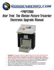
#PRP1764<br />
Star Trek III: <strong>The</strong> <strong>Search</strong> <strong>for</strong> <strong>Spock</strong> <br />
<strong>Phaser</strong> <strong>Prop</strong> <strong>Kit</strong> Assembly Manual<br />
<strong>Roddenberry</strong>.<strong>com</strong> presents the STAR TREK III: <strong>The</strong> <strong>Search</strong> For <strong>Spock</strong> <strong>Phaser</strong> as an<br />
economical alternative <strong>for</strong> those who like to put together their own prop projects.<br />
This kit has all needed parts to <strong>com</strong>plete either one of two designs: the phaser as seen in the movie<br />
and years later on <strong>The</strong> Next Generation in the episode “Final Mission,” or the phaser as originally<br />
conceived by the model shop at Industrial Light and Magic which went through minor detailing<br />
changes to make the finished movie phaser (photos of which appeared in at least one of the<br />
early 1980’s game manuals <strong>for</strong> FASA’s “Star Trek: <strong>The</strong> Role Playing Game”).
2<br />
#PRP1764 - STAR TREK III Ph a s e r Pr o p <strong>Kit</strong> As s e m b l y Ma n u a l<br />
Introduction:<br />
This kit may require some prop or model making experience to finish, and is made hollow <strong>for</strong><br />
incorporation of electronic upgrades. Electronic circuits, working switches, or parts not included.<br />
For reference, due to its design similarity to the TOS phaser prop, the main parts are referred to as<br />
“<strong>Phaser</strong> 1” and “<strong>Phaser</strong> 2”<br />
Parts and instructions specific to the “prototype” or “FASA” phaser are in bold blue.<br />
Parts included with the kit:<br />
• <strong>Phaser</strong> 1 (P1) resin castings top and bottom<br />
• <strong>Phaser</strong> 2 (P2) resin castings -- top “banana” and bottom handgrip/body (both P1 and P2 castings are<br />
made with the original prototype detailing)<br />
• <strong>Phaser</strong> 1 parts:<br />
- Clear red-cast emitter plate<br />
- Force-setting plate with 4 simulated-cast LEDs<br />
- Green-cast LED “trigger”<br />
- Micro-slide switch<br />
- Graphics plate with red and white vinyl strips<br />
- Blue vinyl graphics and plates<br />
- Chrome mylar strip<br />
- Non-functional micro-slide switch casting<br />
- 3 screws (2 @ 2-56 x 3/4”; 1 @ 4-40 x 1/2”)<br />
• <strong>Phaser</strong> 2 parts:<br />
- Clear emitter rod<br />
- Trigger (switch cap) with trigger sleeve<br />
- Left and right side plates<br />
- Three screws (2-56 x 3/8)<br />
- 4 magnets<br />
- Black felt square<br />
Paints needed <strong>for</strong> both phaser versions (spray paints unless noted):<br />
Primer (sandable scratch-filler type)<br />
Zynolyte<br />
Dark Gray Primer or other dark gray paint<br />
Krylon or other brand metallic silver -- or Plastikote 7173 or similar<br />
Semi-Gloss or Gloss Black<br />
Testors Model Master Bright Blue (small jar)<br />
White (small jar) or white paint pen<br />
Matte or semigloss clear spray (optional)
Introduction (continued):<br />
#PRP1764 - STAR TREK III Ph a s e r Pr o p <strong>Kit</strong> As s e m b l y Ma n u a l 3<br />
Tools and other supplies needed:<br />
Sandpaper (320, 400 to 600 grits)<br />
X-Acto or other brand hobby knife<br />
Philips screwdriver<br />
Cyanoacrylate (CA) glue with cure accelerator<br />
5-minute epoxy glue or epoxy gel<br />
Auto body spot putty or modeler’s putty<br />
Small detail paint brush<br />
Masking tape.<br />
If making a movie phaser, you should have a Dremel tool with a bit <strong>for</strong> making slots or a drill with a<br />
1/8” bit, and some small files.<br />
Optional tools and materials:<br />
Dremel tool with 1/8” slot cutting bit<br />
Bondo filler<br />
Soldering iron and solder<br />
Hot glue gun<br />
Pushbutton switch (Radio Shack Momentary Pushbutton Switch part #275-1547)<br />
Two wires <strong>for</strong> the pushbutton switch approximately 6 inches long minimum<br />
For a functioning phaser, you will want a slide switch to use in place of the switch casting, also a<br />
bi-color (red/yellow) square 4-element LED (Hewlett-Packard manufacture, part #HLMP-2950), and<br />
4 @ rectangular red LEDs 2.5 x 7mm -- all used with a working electronic phaser to replace colored<br />
cast substitutes included with the kit.<br />
Obey all materials use instructions!<br />
Start by washing your resin cast parts with a chlorine-based cleanser like Ajax or Comet to wash away<br />
traces of mold release from the surfaces. Also sand away any mold flashing present, and fill in with spot<br />
putty...and sand any objectionable holes, scratches, or other areas with 320-400 grit paper.<br />
Do not paint at this time. Test fit your parts to be sure they’re working out.
4<br />
#PRP1764 - STAR TREK III Ph a s e r Pr o p <strong>Kit</strong> As s e m b l y Ma n u a l<br />
Assembly:<br />
Here are some photos showing the differences<br />
between the two phaser versions.<br />
You have a choice of building up either one of the<br />
two [Figs. 1 to 3].<br />
Note the prototype version doesn’t allow <strong>for</strong><br />
electronic upgrades to the <strong>Phaser</strong> 1 as there<br />
were no LED or other surface lighting effects<br />
designed into it. <strong>The</strong>re are also two silver<br />
details in both sides of the <strong>Phaser</strong> 2 body which<br />
could be thought of as “recharging jacks” or a<br />
“dilithium crystal” power source which were<br />
covered up on the movie phaser by a couple of<br />
detail plates.
#PRP1764 - STAR TREK III Ph a s e r Pr o p <strong>Kit</strong> As s e m b l y Ma n u a l 5<br />
Step 1 (option A):<br />
For either the FASA or Movie version <strong>Phaser</strong>, if you are making a non-functioning dummy prop with a<br />
static trigger, glue the trigger on the trigger sleeve and then onto the <strong>Phaser</strong> 2. Skip to Step 5.<br />
Step 1 (option B):<br />
For either the FASA or Movie version <strong>Phaser</strong>, if you want the trigger to work, or if you’re installing an<br />
electronics upgrade, purchase a momentary pushbutton switch. <strong>The</strong> one re<strong>com</strong>mended is listed under<br />
Optional Tools and Materials, and it <strong>com</strong>es as a four-pack [Fig. 4]. Try inserting the switch cap casting into<br />
the trigger housing -- this should slide in easily and <strong>com</strong>e back out without it hanging up, and remember<br />
the cap will be painted, so take that into consideration. Press on the momentary switch to the switch<br />
cap casting [Figs. 5 and 6] -- this may take some doing as it should be a tight fit, so glue should not be<br />
necessary. But if it’s loose or if you need to enlarge the hole to make it fit, glue it on with a small drop of CA.<br />
Step 2 (do only if choosing option B):<br />
Insert the switch into the trigger sleeve, pushing it in as far as needed <strong>for</strong> the push button action to work,<br />
and glue from the back side with 5-minute epoxy or hot glue. To ensure it will be in the right place, press<br />
both ends together until the glue is cured [Fig. 7].<br />
Step 3 (do only if choosing option B):<br />
If it will be a functioning phaser either now or sometime in the future, solder a couple of wires to the<br />
switch, as you will not be able to get to the switch once inside the phaser body. And make sure you have<br />
plenty of length <strong>for</strong> the wires [Fig. 8].
6<br />
#PRP1764 - STAR TREK III Ph a s e r Pr o p <strong>Kit</strong> As s e m b l y Ma n u a l<br />
Step 4 (do only if choosing option B):<br />
Glue the switch assembly to the <strong>Phaser</strong> 2 body and orient it square to the rest of the phaser<br />
[Figs. 9 and 10].<br />
Step 5 (do <strong>for</strong> all phasers):<br />
<strong>The</strong>re are four magnets included to aid in keeping the <strong>Phaser</strong> 1 attached to the <strong>Phaser</strong> 2 unit. Glue two<br />
magnets to the inside of the <strong>Phaser</strong> 1 bottom shell at the back, the other two to the underside of the<br />
<strong>Phaser</strong> 2 top “banana” casting -- insert them all the way in the holes provided [Fig. 11].<br />
Very important:<br />
Be very sure the magnets are attracting each other so you’ll have a positive lock when the P1 is<br />
inserted in its place -- it will do you no good if the P1 repels the P2 body. This is a very good way to<br />
keep the two phaser parts together during normal handling and play, but there’s a chance the <strong>Phaser</strong><br />
1 can be dislodged off the <strong>Phaser</strong> 2 by violent shaking of the prop or having it catch on something.<br />
If making the non-functioning Prototype/FASA <strong>Phaser</strong> 1, do Step 6.<br />
If making the Movie <strong>Phaser</strong> and/or a functioning <strong>Phaser</strong>, skip to Step 7.
#PRP1764 - STAR TREK III Ph a s e r Pr o p <strong>Kit</strong> As s e m b l y Ma n u a l 7<br />
Step 6 (do if making the non-functioning Prototype/FASA <strong>Phaser</strong> 1):<br />
Glue the nonfunctional slide switch casting to the rectangular hole at the right back corner of the<br />
<strong>Phaser</strong> 1. Also glue on the square light green LED casting into the square hole [Fig.12]. Sand or file<br />
flat both switch and square LED to their respective surfaces if making the prototype/FASA phaser --<br />
the triangle detail is a smooth surface [Fig. 13].<br />
If making the non-functioning Prototype/FASA <strong>Phaser</strong> 1, skip to Step 12.<br />
Step 7 (do <strong>for</strong> Movie <strong>Phaser</strong> only, not <strong>for</strong> Prototype/FASA <strong>Phaser</strong>):<br />
To modify the parts <strong>for</strong> the movie phaser, sand the raised detail rings from the two recharging jacks of the<br />
<strong>Phaser</strong> 2 until smooth with the rest of the body surface, and be careful you do not sand the three ribs<br />
[Fig. 14]. If you like, you may use Bondo to fill in the two holes and sand until smooth. <strong>The</strong>n glue on the two<br />
side plates with CA glue, being careful you don’t use too much -- don’t let it ooze out the plate edges<br />
[Figs. 15 and 16].<br />
Step 8 (do <strong>for</strong> Movie <strong>Phaser</strong> only, not <strong>for</strong> Prototype/FASA <strong>Phaser</strong>):<br />
With the <strong>Phaser</strong> 1 top body, remove the dividing line in the center using your knife and/or other tools at your<br />
disposal such as a chisel or file, or your Dremel tool [Fig. 17].
8<br />
#PRP1764 - STAR TREK III Ph a s e r Pr o p <strong>Kit</strong> As s e m b l y Ma n u a l<br />
Step 9 (do <strong>for</strong> Movie <strong>Phaser</strong> only, not <strong>for</strong> Prototype/FASA <strong>Phaser</strong>):<br />
Once it’s smoothed out, take the <strong>for</strong>ce setting plate and place it on the P1 body, then with a pencil or pen<br />
trace out the four rectangular LED holes [Fig. 18].<br />
Step 10 (do <strong>for</strong> Movie <strong>Phaser</strong> only, not <strong>for</strong> Prototype/FASA <strong>Phaser</strong>):<br />
Cut through all your traced holes with a Dremel tool, or drill and file the holes (the casting is thin at that<br />
area), making them large enough <strong>for</strong> your (real or simulated) LEDs to fit [Figs. 19 and 20].<br />
Step 11 (do <strong>for</strong> Movie <strong>Phaser</strong> only, not <strong>for</strong> Prototype/FASA <strong>Phaser</strong>):<br />
Glue the <strong>for</strong>ce setting plate to the <strong>Phaser</strong> 1 with CA or epoxy. Glue the thin rectangular styrene piece at the<br />
scribed rectangle on the main plate [Figs. 21 and 22]. If it will be a non-functioning phaser, glue the red<br />
slide switch casting in the small rectangular hole to the back right side. Don’t let it stick outside the surface,<br />
and do not glue any of the LEDs <strong>for</strong> now.
#PRP1764 - STAR TREK III Ph a s e r Pr o p <strong>Kit</strong> As s e m b l y Ma n u a l 9<br />
PAINTING:<br />
Step 12 (All <strong>Phaser</strong>s):<br />
With masking tape, mask the inside of at least your <strong>Phaser</strong> 1 top shell in such a way that the interior is<br />
protected and the outer edge is exposed. You will see this edge when the phaser is screwed together, and<br />
you’ll need to glue to the inside of the shell -- glue does not stick well to painted surfaces. Hang your phaser<br />
parts with a stiff wire. Spray primer the first coat, let dry. Check <strong>for</strong> holes or dents you may have missed<br />
previously, fill with spot putty, then sand and primer again until it’s all smooth.<br />
[<strong>Phaser</strong> 1] Spray your first coat of Semi-Gloss (or Gloss) Black both outside and inside, wet sand with 600<br />
grit paper, then spray a final coat and let dry <strong>for</strong> several hours or overnight [Fig. 23].<br />
[<strong>Phaser</strong> 2] <strong>The</strong> re<strong>com</strong>mended paint <strong>for</strong> the main color is Zynolyte Dark Gray Primer. Since this can be<br />
difficult to find, you can use something else that’s a very dark, almost black gray, or even black like the<br />
semi-gloss black you use to paint the <strong>Phaser</strong> 1, or a flat black or black primer. A good brand to get if you<br />
can find it is World Of Color Dark Primer; this matches almost exactly to the Zynolyte primer color.<br />
Step 13 (All <strong>Phaser</strong>s):<br />
Secure the top “banana” body part to the handgrip with three 2-56 x 3/8” screws so it will be painted as one<br />
unit. Note this design allows <strong>for</strong> interior access to the P2 to change batteries in a working phaser prop<br />
[Figs. 24 and 25].<br />
If this is a non-functioning phaser without electronics, you can either leave the method of attachment as is,<br />
or you can glue the two parts together permanently and fill in the screw holes with Bondo, or make sure the<br />
screws are sunk in slightly below the surface and fill those in. Beware that if you do glue the <strong>Phaser</strong> 2<br />
parts together you won’t be able to take them apart later.<br />
Spray the <strong>Phaser</strong> 2 with Zynolyte Dark Gray Primer or similar paint, wet sand with 600 grit paper, then<br />
spray a second coat of Zynolyte.
10<br />
#PRP1764 - STAR TREK III Ph a s e r Pr o p <strong>Kit</strong> As s e m b l y Ma n u a l<br />
Step 14 (do only if making the Prototype/FASA <strong>Phaser</strong> 2):<br />
Mask the emitter detailing as shown. This area will remain dark gray/black [Fig. 26].<br />
Step 15 (All <strong>Phaser</strong>s):<br />
<strong>The</strong> next step can be somewhat tricky; you’ll be spraying a fine mist of metallic silver on the <strong>Phaser</strong> 2. You<br />
should have as new a can of paint as possible, and it should not be a cold can (put it in a warm place such<br />
as a sunlit window to warm the can be<strong>for</strong>e you try it).<br />
You may substitute Plastikote 7173 or other metallic gray or silver <strong>for</strong> misting onto the gray/black. <strong>The</strong><br />
7173 is re<strong>com</strong>mended if you are painting black as your color. It will help to make the overall finish more like<br />
misted regular silver on gray.<br />
Hold the phaser body as far away from you and the paint can as possible, then let loose with a fog of paint<br />
[Fig. 27]. <strong>The</strong> effect is like how mist accumulates on your windshield when driving in a fog or a light misty<br />
rain, and you’ll end up with a uni<strong>for</strong>m light “sandpapery” finish. Make sure all <strong>Phaser</strong> 2 surfaces are<br />
misted as evenly as possible.<br />
A cold can, or older or used and almost empty can, may produce unwanted large droplets. So if you get<br />
larger drops on your phaser, you may have to touch it up with a small paint brush, re-paint your phaser in<br />
that spot, or you may have to re-paint the whole thing. When it’s good, if you like, you can spray a final coat<br />
of matte or semi-gloss clear to protect the misted silver finish. Let the finish cure be<strong>for</strong>e proceeding.
#PRP1764 - STAR TREK III Ph a s e r Pr o p <strong>Kit</strong> As s e m b l y Ma n u a l 11<br />
Step 16 (do only if making the Prototype/FASA <strong>Phaser</strong> 2):<br />
Mask off the <strong>Phaser</strong> 2 so only the two recharging jacks are exposed to the outer rings, then paint in<br />
Metallic Silver or a finish that will simulate machined metal [Fig. 28]. Remove all masking, including<br />
the emitter masking.<br />
FINAL ASSEMBLY:<br />
Step 17 (All <strong>Phaser</strong>s):<br />
Glue the clear emitter rod into the phaser emitter using 5-minute epoxy, with the machined end facing out<br />
and flush to the casting [Fig. 29].<br />
Step 18 (do only if making the Prototype/FASA <strong>Phaser</strong> 1):<br />
On the <strong>Phaser</strong> 1, glue the red emitter plate in place with 5-minute epoxy to either the top or bottom<br />
shell [Figs. 30 and 31]. Screw the two shells together with the 2 @ 2-56 x 3/4” and the 4-40 x 1/2”<br />
screws.
12<br />
#PRP1764 - STAR TREK III Ph a s e r Pr o p <strong>Kit</strong> As s e m b l y Ma n u a l<br />
Step 19 (do only if making the Prototype/FASA <strong>Phaser</strong> 1):<br />
Apply the blue vinyl stickers to the top face where shown [Fig. 32]. Apply the chrome mylar tape<br />
around the perimeter of the <strong>Phaser</strong> 1, and a small strip of mylar tape to cover the lower right<br />
rectangular slide switch casting at the top [Figs. 1 and 33].<br />
Step 20 (do <strong>for</strong> Movie <strong>Phaser</strong> only, not <strong>for</strong> Prototype/FASA <strong>Phaser</strong>)<br />
If you’re not installing working LEDs and are using the castings, paint with a detailing brush the perimeter<br />
edge of the green LED casting in white (or use a white paint pen) [Fig. 34], then glue it into the triangle hole<br />
as in Fig. 12. Glue the red LED blocks in place with epoxy [Fig. 35]. Note that you can mix in a little baking<br />
soda in with the epoxy to make it thicker, and it will help to keep the glue from oozing through the LED<br />
holes to the outside. <strong>The</strong>se LEDs may stick out a little, set flush, or be depressed, but be sure you get them<br />
all even. <strong>The</strong>n apply the red and white strips to the rectangle on the <strong>for</strong>ce setting plate you glued on earlier.<br />
NOTE: with the phaser facing <strong>for</strong>ward, the red one is to the right [consult Fig. 1].<br />
If this is a working phaser, glue a working slide switch into the P1 hole at the back right, and be very careful<br />
you don’t get any glue in the switch, as it is likely you’ll be using it to turn on and off your circuit.<br />
Glue the red emitter plate to either the top or bottom shell [Figs. 30 and 31], then screw the <strong>Phaser</strong> 1<br />
shells together with the 2 @ 2-56 x 3/4” and the 4-40 x 1/2” screws.<br />
If you’re making an electronic light-up phaser, note that if you can’t find the right size of red LEDs <strong>for</strong> the<br />
<strong>for</strong>ce setting plate, you can put in LEDs below the transparent red-cast ones and they should light up just<br />
as well. Other HP manufactured square LEDs (.400 x .400” size) may also work <strong>for</strong> you if you are unable to<br />
locate the bi-color ones.
#PRP1764 - STAR TREK III Ph a s e r Pr o p <strong>Kit</strong> As s e m b l y Ma n u a l 13<br />
Step 21 (All <strong>Phaser</strong>s):<br />
Stick the black felt piece on the <strong>Phaser</strong> 2 up inside where the <strong>Phaser</strong> 1 nose is captured to help in keeping<br />
the <strong>Phaser</strong> 1 from getting paint damage [Fig. 36].<br />
Step 22 (All <strong>Phaser</strong>s):<br />
Finally, with your fine detail paint brush, lightly paint the three thin strips on both sides of the <strong>Phaser</strong> 2 with<br />
Testors Model Master Bright Blue [Fig. 37], insert the <strong>Phaser</strong> 1 into the <strong>Phaser</strong> 2, and your Star Trek III:<br />
<strong>The</strong> <strong>Search</strong> For <strong>Spock</strong> <strong>Phaser</strong> is finished!<br />
IMPORTANT NOTES:<br />
<strong>The</strong> physical reproduction by any means known or yet to be invented (including molding<br />
and recasting, reverse-engineering, and stereo lithography scanning and printing) of this<br />
<strong>Roddenberry</strong>.<strong>com</strong> Star Trek III <strong>Phaser</strong> <strong>Prop</strong> <strong>Kit</strong> or its parts and graphics, or reproducing<br />
any pre-existing parts and graphics, is expressly prohibited under U.S. and international<br />
copyright and product protection laws.<br />
Copyright © 2009 <strong>Roddenberry</strong> Productions.<br />
Star Trek and related marks and logos are Trademarks of CBS Studios Inc. All rights reserved.