The Search for Spock Phaser Prop Kit - Roddenberry.com
The Search for Spock Phaser Prop Kit - Roddenberry.com
The Search for Spock Phaser Prop Kit - Roddenberry.com

Create successful ePaper yourself
Turn your PDF publications into a flip-book with our unique Google optimized e-Paper software.
12<br />
#PRP1764 - STAR TREK III Ph a s e r Pr o p <strong>Kit</strong> As s e m b l y Ma n u a l<br />
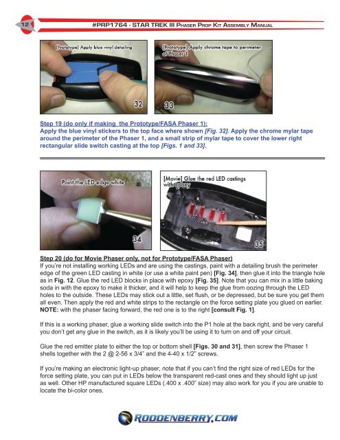
Step 19 (do only if making the Prototype/FASA <strong>Phaser</strong> 1):<br />
Apply the blue vinyl stickers to the top face where shown [Fig. 32]. Apply the chrome mylar tape<br />
around the perimeter of the <strong>Phaser</strong> 1, and a small strip of mylar tape to cover the lower right<br />
rectangular slide switch casting at the top [Figs. 1 and 33].<br />
Step 20 (do <strong>for</strong> Movie <strong>Phaser</strong> only, not <strong>for</strong> Prototype/FASA <strong>Phaser</strong>)<br />
If you’re not installing working LEDs and are using the castings, paint with a detailing brush the perimeter<br />
edge of the green LED casting in white (or use a white paint pen) [Fig. 34], then glue it into the triangle hole<br />
as in Fig. 12. Glue the red LED blocks in place with epoxy [Fig. 35]. Note that you can mix in a little baking<br />
soda in with the epoxy to make it thicker, and it will help to keep the glue from oozing through the LED<br />
holes to the outside. <strong>The</strong>se LEDs may stick out a little, set flush, or be depressed, but be sure you get them<br />
all even. <strong>The</strong>n apply the red and white strips to the rectangle on the <strong>for</strong>ce setting plate you glued on earlier.<br />
NOTE: with the phaser facing <strong>for</strong>ward, the red one is to the right [consult Fig. 1].<br />
If this is a working phaser, glue a working slide switch into the P1 hole at the back right, and be very careful<br />
you don’t get any glue in the switch, as it is likely you’ll be using it to turn on and off your circuit.<br />
Glue the red emitter plate to either the top or bottom shell [Figs. 30 and 31], then screw the <strong>Phaser</strong> 1<br />
shells together with the 2 @ 2-56 x 3/4” and the 4-40 x 1/2” screws.<br />
If you’re making an electronic light-up phaser, note that if you can’t find the right size of red LEDs <strong>for</strong> the<br />
<strong>for</strong>ce setting plate, you can put in LEDs below the transparent red-cast ones and they should light up just<br />
as well. Other HP manufactured square LEDs (.400 x .400” size) may also work <strong>for</strong> you if you are unable to<br />
locate the bi-color ones.