“DusTbusTeR” PhaseR PRoP - Roddenberry.com
“DusTbusTeR” PhaseR PRoP - Roddenberry.com
“DusTbusTeR” PhaseR PRoP - Roddenberry.com
Create successful ePaper yourself
Turn your PDF publications into a flip-book with our unique Google optimized e-Paper software.
#PRP1745<br />
The Next Generation 1st Season "Dustbuster"<br />
Phaser Prop Kit Assembly Manual<br />
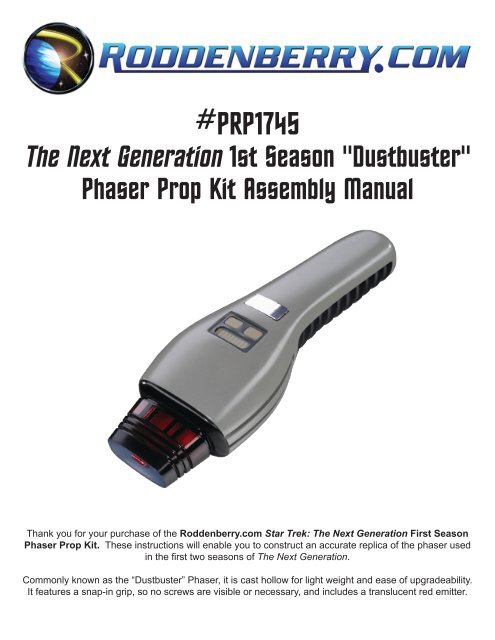
Thank you for your purchase of the <strong>Roddenberry</strong>.<strong>com</strong> Star Trek: The Next Generation First Season<br />
Phaser Prop Kit. These instructions will enable you to construct an accurate replica of the phaser used<br />
in the first two seasons of The Next Generation.<br />
Commonly known as the “Dustbuster” Phaser, it is cast hollow for light weight and ease of upgradeability.<br />
It features a snap-in grip, so no screws are visible or necessary, and includes a translucent red emitter.
2<br />
#PRP1745 - Th e Ne x t Generation 1s t Se a s o n “Du s t b u s t e r” Ph a s e r Pr o p Kit As s e m b l y Ma n u a l<br />
BASIC LAYOUT AND INVENTORY<br />
Parts List:<br />
• 1 Main Body<br />
• 1 Emitter<br />
• 1 Grip<br />
• 2 Bullet Catches<br />
• 1 LED Detail Plate<br />
• 1 Trigger and<br />
Force Setting<br />
Button Template<br />
• 1 .090” Plastic Strip<br />
for buttons<br />
• 1 .040” Plastic Strip<br />
for trigger button<br />
Tools and supplies:<br />
(available at your local hardware or hobby stores)<br />
• Hobby Knife<br />
• Automotive spot putty<br />
• Cyanoacrylate Glue (“gap filling” type<br />
re<strong>com</strong>mended)<br />
• Sandpaper (240, 400, and up to 600 grit)<br />
• Low tack glue (“Glue Stik”) or double-sided tape<br />
• Masking tape (low-tack blue tape re<strong>com</strong>mended)<br />
• Hot glue gun and hot glue<br />
• Paint brushes (small size for painting the LEDs,<br />
a larger brush for the display background)<br />
Optional tool:<br />
• File (flat or half-round)<br />
SPRAY PAINTS:<br />
• Spray primer (both gray and black<br />
sandable type)<br />
• Krylon “Dove Gray” or “Stone Gray”<br />
• Krylon or other brand Silver or similar<br />
• Semi-Gloss or Gloss Black<br />
• Transparent Blue or Metallic Light Blue<br />
Brush PAINTS:<br />
• Light Green<br />
• Dark gray (this may be a spray paint if desired)<br />
• Beige (also can be a spray paint)<br />
Always follow manufacturer’s instructions and safety tips on your materials.<br />
Always work in a well-ventilated area when using putty, paints, and glues; and when sanding.
#PRP1745 - Th e Ne x t Generation 1s t Se a s o n “Du s t b u s t e r” Ph a s e r Pr o p Kit As s e m b l y Ma n u a l 3<br />
Step 1: Wash your parts with soap and water to remove traces of mold release before starting.<br />
Step 2: Test fit the LED plate, sand it if necessary until it looks good and fits properly. Also test fit the emitter<br />
and the grip.<br />
Step 3: Sand away the sprues and any mold seams on the body. Putty any objectionable bubbles or lines,<br />
sanding marks, etc., and sand until smooth.
4<br />
#PRP1745 - Th e Ne x t Generation 1s t Se a s o n “Du s t b u s t e r” Ph a s e r Pr o p Kit As s e m b l y Ma n u a l<br />
Step 4: When the body is prepared, hang the body on a hook and spray your first coat of gray primer.<br />
When dry, putty and sand any pits or dips that weren’t visible before painting. When you have a surface<br />
you’re pleased with, spray a fresh coat of primer over the sanded areas before proceeding.<br />
Step 5: Spray your Dove Gray (a.k.a. Stone Gray) finish coat next. Two light coats are better than one<br />
heavy coat; this may be wet sanded between coats with 600 or finer grit sandpaper if desired. When you<br />
have the final gray finish, lightly mist a fog of silver spray paint over all the body to give you the pictured<br />
finish.<br />
Step 6: Be sure you check to see that visible hidden areas like the inside grip area is also painted and finished.<br />
Step 7: Allow several hours or overnight for the finish to cure before handling.
#PRP1745 - Th e Ne x t Generation 1s t Se a s o n “Du s t b u s t e r” Ph a s e r Pr o p Kit As s e m b l y Ma n u a l 5<br />
Step 8: Mask around the top display block with the masking tape and either brush-on or spray a coat of<br />
dark gray in the visible area.<br />
Step 9: Prepare the grip like you did the body -- cut off the sprue and sand the mold seams until smooth<br />
and putty if necessary. Lightly sand the surface with 400-grit sandpaper to allow the paint to stick better.<br />
Step 10: Prepare the holes in both ends of the grip; clear away with your knife if necessary, then test fit the<br />
bullet catches. The catches should fit snugly but not be too difficult to push in. Remove the catches before<br />
painting.
6<br />
#PRP1745 - Th e Ne x t Generation 1s t Se a s o n “Du s t b u s t e r” Ph a s e r Pr o p Kit As s e m b l y Ma n u a l<br />
Step 11: Make a hook as shown using a wire hanger, then spray primer (with gray or black), then spray<br />
the color coats with the semi-gloss or gloss black. A gloss finish will look better, but it takes longer to dry<br />
and will show off more surface flaws than the duller paints. Allow to cure several hours or overnight before<br />
handling.<br />
Step 12: With the cyanoacrylate glue, apply a small amount on one edge of one grip hole and push in a<br />
bullet catch until set in place.<br />
Step 13: Do the same with the other end.<br />
Step 14: Be sure that you don’t accidentally get glue in the catches themselves, press the catch balls in to<br />
be sure they still function.
#PRP1745 - Th e Ne x t Generation 1s t Se a s o n “Du s t b u s t e r” Ph a s e r Pr o p Kit As s e m b l y Ma n u a l 7<br />
Step 15: Prepare the emitter by sanding the mold seams and lightly sanding the surfaces. Be very careful<br />
around the lightly detailed areas, you do not want to sand the squared details off!<br />
Step 16: Mask the “inner” details as shown. Measure the width of the squares and cut your tape to that<br />
width, then wrap around the emitter, mark the lines on the tape, and cut off the “strips” all around the<br />
emitter. Or cut the squares out of a length of tape and place individually on the emitter. Also apply some<br />
tape on the little tip area at the front end, and the block of material that goes into the phaser.<br />
Step 17: You may, if desired, mask the three grooves -- some phasers were unpainted red there and some<br />
were black painted; it’s a matter of personal preference.<br />
Step 18: Spray black primer onto the emitter, then your finish black coats with the same semi-gloss or<br />
gloss black that you painted the grip. As with the body, you can wet sand the emitter for the ultimate<br />
smooth finish -- allow the water to dry <strong>com</strong>pletely before spraying the next coat. Allow to cure several hours<br />
before handling.
8<br />
#PRP1745 - Th e Ne x t Generation 1s t Se a s o n “Du s t b u s t e r” Ph a s e r Pr o p Kit As s e m b l y Ma n u a l<br />
Step 19: When the paint is cured, pry off the masking tape from everywhere except the front tip -- leave<br />
that tape on! You may need to lightly use your hobby knife on the tape edges to separate them and to keep<br />
from lifting your fresh paint job.<br />
Step 20: To paint the blue front end, mask off the rest of the emitter body and the tip in the middle, then spray<br />
silver on the front. When dry, spray transparent blue on top of the silver; this gives an attractive translucent<br />
“candy” car look to that part of the phaser. Or spray with a metallic light blue, this will look about the same.<br />
Step 21: When cured enough to handle, remove the masking tape and admire your handiwork!<br />
Step 22: With the paper template of the buttons, cut off the two smaller buttons and tack this down with<br />
the glue stik or double sided tape onto the .090 piece of plastic. Tack the large button down on the piece of<br />
.040 plastic.
#PRP1745 - Th e Ne x t Generation 1s t Se a s o n “Du s t b u s t e r” Ph a s e r Pr o p Kit As s e m b l y Ma n u a l 9<br />
Step 23: Carefully cut the buttons to size and file or sand to final size.<br />
Step 24: Test fit on the body and sand more if needed.<br />
Step 25: Secure the buttons on a Popsicle stick, cardboard, etc. and spray primer. The two small buttons<br />
are beige in color, these can be brushed-on or spray-painted. The trigger button is silver.<br />
Step 26: When dry, test fit the buttons.
10<br />
#PRP1745 - Th e Ne x t Generation 1s t Se a s o n “Du s t b u s t e r” Ph a s e r Pr o p Kit As s e m b l y Ma n u a l<br />
Step 27: Scrape away the paint on the body where the buttons (and the LED detail plate) will be glued to --<br />
glue joints work better on resin than on paint. Apply glue to the button depressions (NOT the LED slot) and<br />
place the buttons. Don’t use so much glue that it seeps out of the edges and onto your finish.<br />
Step 28: Prepare the LED plate by sanding flat the bottom side and making sure it fits in the hole properly.<br />
Step 29: The LED plate simulates a 10-element green bar graph LED array with green elements bordered<br />
by a light gray. If the resin color is not to your liking, you may spray primer the surface, then spray a coat of<br />
Dove Gray. When dry, or if the resin color is good enough, cut strips of masking tape and apply on all the<br />
raised areas of the LED plate. Brush on the light green paint to the exposed areas.
#PRP1745 - Th e Ne x t Generation 1s t Se a s o n “Du s t b u s t e r” Ph a s e r Pr o p Kit As s e m b l y Ma n u a l 11<br />
Step 30: When dry, remove the tape.<br />
Step 31: Apply glue to the LED depression and install the LED plate.<br />
Step 32: Scrape away paint from the inside of the large phaser cavity where the emitter goes.
12<br />
#PRP1745 - Th e Ne x t Generation 1s t Se a s o n “Du s t b u s t e r” Ph a s e r Pr o p Kit As s e m b l y Ma n u a l<br />
Step 33: With the hot glue gun, spread a quantity of hot glue all around the inside of the front hole and<br />
push in the emitter, again making sure you don’t get glue on the outside surfaces. You have a little time to<br />
get enough hot glue in and to install and align the emitter onto the phaser before the hot glue hardens.<br />
Step 34: Snap in your grip...
#PRP1745 - Th e Ne x t Generation 1s t Se a s o n “Du s t b u s t e r” Ph a s e r Pr o p Kit As s e m b l y Ma n u a l 13<br />
Step 35: ...and you have a <strong>com</strong>pleted TNG First Season “Dustbuster” Phaser!<br />
IMPORTANT NOTES:<br />
The physical reproduction by any means known or yet to be invented (including recasting<br />
and/or reverse-engineering or 3D scanning/printing) of the <strong>Roddenberry</strong>.<strong>com</strong> Next Generation<br />
First Season Phaser Kit or any of its parts is expressly prohibited under U.S. and International<br />
copyright and product protection laws.<br />
Copyright © 2009 <strong>Roddenberry</strong> Productions.<br />
Star Trek and related marks and logos are Trademarks of CBS Studios Inc. All rights reserved.


