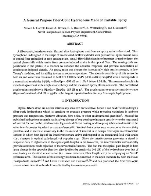
A General Purpose Fiber-Optic Hydrophone Made of Castable Epoxy
A General Purpose Fiber-Optic Hydrophone Made of Castable Epoxy
A General Purpose Fiber-Optic Hydrophone Made of Castable Epoxy
You also want an ePaper? Increase the reach of your titles
YUMPU automatically turns print PDFs into web optimized ePapers that Google loves.
A <strong>General</strong> <strong>Purpose</strong> <strong>Fiber</strong>-<strong>Optic</strong> <strong>Hydrophone</strong> <strong>Made</strong> <strong>of</strong> <strong>Castable</strong> <strong>Epoxy</strong><br />
Steven L. Garrett, David A. Brown, B. L. Beaton(a), K. Wetterskog(a), and J. Serocki(a)<br />
Naval Postgraduate School, Physics Department, Code PH/Gx<br />
Monterey, CA 93943<br />
ABSTRACT<br />
A fiber-optic, interferometric, flexural disk hydrophone cast from an epoxy resin is described. This<br />
hydrophone is designed in the shape <strong>of</strong> an enclosed, hollow cylinder with pairs <strong>of</strong> flat, spiral wound coils<br />
<strong>of</strong> optical fiber embedded in each sensing plate. An all-fiber Michelson interferometer is used to detect the<br />
optical phase shift which results from pressure induced strains in the optical fiber. The sensing coils are<br />
positioned in the plates in a manner to enhance the acoustic response and provide cancelation <strong>of</strong><br />
acceleration induced signals. An epoxy resin was chosen for its relatively high tensile strength, its low<br />
Young's modulus, and its ability to cure at room temperature. The acoustic sensitivity <strong>of</strong> this sensor in<br />
both air and water was measured to be 0.277 0.005 rad/Pa (-131.2 dB re radfliPa) which corresponds to<br />
a normalized sensitivity 4/p = a1n4/ap<br />
= -297 dB re 1 iPa1 below 1 .0 kHz. This measured result is in<br />
excellent agreement with simple elastic theory and the measured epoxy elastic constants. The normalized<br />
acceleration sensitivity is 3/4aa = ln/aa -163 dB re g1. The acceleration-to-acoustic sensitivity ratio<br />
(figure-<strong>of</strong>-merit) <strong>of</strong> -134 dB re g4tPa is the largest reported to date for any fiber-optic hydrophone.<br />
1. INTRODUCTION<br />
<strong>Optic</strong>al fibers alone are neither intrinsically sensitive nor selective, hence it can be difficult to design a<br />
fiber-optic hydrophone which is sensitive to acoustic pressure while rejecting variations in ambient<br />
pressure and temperature, platform vibration, flow noise, or other environmental quantities1. Most <strong>of</strong> the<br />
published hydrophone research has involved the use <strong>of</strong> one coating to increase sensitivity to the measurand<br />
<strong>of</strong> interest for one on the interferometer legs and a different coating or decoupling scheme to desensitize the<br />
other interferometer leg which acts as a reference2'3. We feel that a better way to overcome the selectivity<br />
problem and to increase sensitivity to the measurand <strong>of</strong> interest is to design fiber-optic interferometric<br />
sensors in which both legs <strong>of</strong> the interferometer are active and respond to the measurand field with strains<br />
(i.e., changes in optical path-length) <strong>of</strong> opposite sign. Since the interferometer generates a signal in<br />
response only to differences in the optical path lengths in the two arms, the interferometer automatically<br />
provides common-mode rejection <strong>of</strong> the unwanted influences. The fact that the optical path-length in both<br />
arms change in the opposite direction also doubles the sensitivity (+6 dB) <strong>of</strong> the hydrophone over that <strong>of</strong><br />
one having an identical construction (i.e., same materials, fiber length, etc.) but employing an "ideal"<br />
reference arm. The success <strong>of</strong> this strategy has been documented in the open literature by both the Naval<br />
Postgraduate Schoo1418 and Litton Guidance and Control19'2° and has produced the first fiber-optic<br />
sensor whose detection threshold was limited by its own temperature21.<br />
SPIE Vol. 1367 <strong>Fiber</strong> <strong>Optic</strong> and Laser Sensors VIII (1990) / 13
2. DUAL FLEXURAL PLATE HYDROPHONE ELEMENT DESIGN<br />
2 . 1 Pressure and Acceleration Response<br />
When .a thin circular plate is subject to a pressure differential across its surface, it will deform and<br />
therefore experience a surface strain which is compressive on one side and expansive on the other. This<br />
fact has been used previously to develop a hydrophone element using piezoelectric polymer films as the<br />
strain transducers22'23. We have applied this strategy to fiber-optic hydrophone designs by bonding flat<br />
spiral coils <strong>of</strong> optical fiber to both surfaces12 14,17, 1 8 jf the two coils act as the two legs <strong>of</strong> an<br />
interferometer, the plate becomes the transduction mechanism in a push-pull fiber-optic hydrophone.<br />
A single-plate hydrophone will also sense accelerations in the direction normal to the plate surface<br />
because the mass <strong>of</strong> the plate is not zero. Such an acceleration would produce a deflection which is equal<br />
to that produced by a pressure differential given by the product <strong>of</strong> the plate mass and its acceleration<br />
divided by the surface area <strong>of</strong> the plate. The acceleration sensitivity can be reduced by using two identical<br />
plates and four coils as shown schematically in Figures 1 and 2. When the element is subjected to an<br />
excess external pressure, both plates are displaced inward toward the air gap. This deformation causes the<br />
length <strong>of</strong>both Al and A2 to decrease while both Bi and B2 increase producing a "push-pull" enhancement<br />
<strong>of</strong> the optical path length change due to the applied pressure excess. The signs <strong>of</strong> these changes would<br />
reverse for a pressure reduction. This doubles the element's sensitivity to pressure over a single plate<br />
hydrophone <strong>of</strong> identical design.<br />
- If the entire sensor element is accelerated in a direction which is normal to the plate surface, then the<br />
two plates move in unison and the length <strong>of</strong> Al and B2 would increase while the length <strong>of</strong> A2 and Bl<br />
would decrease. The signs <strong>of</strong> these changes would reverse for a reversal in the direction <strong>of</strong> acceleration.<br />
Since the coils in each arm <strong>of</strong> the interferometer ideally experience no net change in length in either arm,<br />
AA1 + L\A2 = AB1 + EB2 = 0, the element is, in principal, immune to accelerations. If the plates, and the<br />
location <strong>of</strong> the fiber-optic coils in each plate, are not identical, the cancelation will not be optimized, so<br />
careful attention has been paid in the fabrication process to make these elements as symmetric as possible<br />
about both the air gap and the rotation axis.<br />
Al<br />
A2<br />
3 dB<br />
Bl 52<br />
Fig. 1. <strong>Fiber</strong>-optic Michelson interferometer. Each sensing leg consists <strong>of</strong> two flat spiral coils 4.50m in<br />
length and 4.0 cm in diameter. The two coils labeled Al and A2 are placed on the outer surfaces <strong>of</strong> the<br />
sensing plates and the two coils B 1 and B2 are placed on the inner surfaces which face the air gap.<br />
14 / SPIE Vol. 1367 <strong>Fiber</strong> <strong>Optic</strong> and Laser Sensors VIII (1990)
ATMOSPHERIC PRESSURE<br />
Sensing Plate 1<br />
(a)<br />
<strong>Fiber</strong> Coils<br />
:: r5::::e: Air Gap<br />
AirGap<br />
Sensing Plate 2<br />
(a)<br />
PRESSURE RESPONSE<br />
1<br />
(b)<br />
Sensing Plates<br />
(b)<br />
TEST DEPTH<br />
(C)<br />
(C)<br />
Fig. 2. (Left) Schematic representation <strong>of</strong> the four-coil, dual-plate hydrophone element showing a crosssectional<br />
view (a) with the dimensions <strong>of</strong> the plates, air gap, and stem (coupler housing). The location <strong>of</strong><br />
the fused evanescent wave directional coupler and the fiber coils is shown in cross-section in (b) and in<br />
plan view in (c).<br />
Fig. 3. (Right) Static pressure response <strong>of</strong> a dual-plate flexural disk hydrophone. Cross-sectional views<br />
show the position <strong>of</strong> the plates and the air gap at (a) atmospheric pressure, (b) operating pressure, and (c)<br />
maximum operating depth where the plates touch.<br />
2.2 Dynamic Flexural Plate Theory<br />
We have previously constructed and tested several flexural plate hydrophone designs using 6061-T6<br />
aluminium and have found that their measured sensitivity and their theoretical sensitivity, based on the<br />
elastic properties <strong>of</strong> the plate material and the boundary conditions, are in excellent agreement for both<br />
hydrostatic and acoustic pressure fie1ds1214'17. The sensitivity, M = (a/P), <strong>of</strong> the dual-plate, fourcoil<br />
hydrophone element, assuming that the perimeter <strong>of</strong> the plate is rigidly clamped, can be expressed in<br />
terms <strong>of</strong> the length <strong>of</strong> the optical fiber in one leg, L, the elastic properties <strong>of</strong> the plate material, and the plate<br />
and fiber coils' physical dimensions.<br />
SPIE Vol. 1367 <strong>Fiber</strong> <strong>Optic</strong> and Laser Sensors VIII (1990) / 15
M=a<br />
8icnL<br />
2<br />
- b2 - c2)<br />
(1)<br />
Here 4 represents the optical pathlength in radians and P is the applied excess acoustic pressure. E and<br />
are the Young's modulus and Poisson's ratio <strong>of</strong> the plate material, 2h is the plate thickness, and a,b, and<br />
c, are the radius <strong>of</strong> the plate and the maximum and minimum spiral coil radii respectively. The wavelength<br />
<strong>of</strong> light in vacuum is , and n is the effective index <strong>of</strong> refraction <strong>of</strong> the optical fiber core. The derivation <strong>of</strong><br />
this result and similar results for simply supported plates with bonded optical fiber spirals have been<br />
published elsewhere13'16'17.<br />
It is conventional to normalize this sensitivity to provide a comparison with other fiber-optic<br />
hydrophones that may use different mechanical designs, fiber lengths, optical wavelengths, and glasses<br />
with different indices <strong>of</strong> refraction. The normalized sensitivity, M = = is<br />
determined by dividing the acoustic sensitivity by the optical path length (in radians <strong>of</strong> phase) <strong>of</strong> one leg <strong>of</strong><br />
the sensor. This convention has been used because most early interferometric sensors use one leg as a<br />
reference leg. The sensitivity can be expressed in a particularly simple form for two plates totally wrapped<br />
on each side with optical fiber and having ideal clamped boundary conditions as<br />
M=O.52—<br />
(2)<br />
Hence, the product <strong>of</strong> the sensitivity and the square <strong>of</strong> the fundamental plate resonance frequency, f02, is a<br />
constant which depends only upon the wavenumber <strong>of</strong> the light in the fiber, kg 2ltflIX, the density <strong>of</strong> the<br />
plate material, p, and the outside diameter <strong>of</strong> the optical fiber, D. For the simply supported case, the prefactor<br />
in (2) is equal to 0. 125 (5 + c)/(1 + ). When 0.27, the pre-factors for both cases are identical.<br />
The fundamental resonance frequency <strong>of</strong> the plate is given by<br />
f0=A2J1—4F E (3)<br />
ita2 V 12(1-&)p<br />
where A2 = 10.2 for a clamped plate. For a simply supported plate, A2 4.9, and is a very weak function<br />
<strong>of</strong> Poisson's ratio.<br />
By Newton's Second Law, the acceleration, a, <strong>of</strong> a plate normal to its surface produces a force which<br />
is the product <strong>of</strong> the mass <strong>of</strong> the plate and its acceleration. That force, divided by the area <strong>of</strong> the plate,<br />
produces an equivalent acceleration induced pressure. One can use this "equivalence" to write an<br />
expression for the acceleration sensitivity, Ma, for a plate <strong>of</strong> mass m = 2itpha2.<br />
M=2.=2Mhp<br />
(4)<br />
16 / SP/E Vol. 1367 <strong>Fiber</strong> <strong>Optic</strong> and Laser Sensors Vii (1990)
The reader is reminded that M is the acoustic sensitivity as defined in equation (1). This result is useful in<br />
the determination <strong>of</strong> how successful the dual-plate design has been in canceling the acceleration induced<br />
forces. An ideal acceleration canceling hydrophone would have a measured Macc which would be<br />
identically zero. This, however, is very difficult to achieve since the physical dimensions, the plate<br />
boundary condition, the plate mass, and the length <strong>of</strong> fiber in each coil and their distance from the plate's<br />
neutral axis would all have to be identical for both sensing plates.<br />
2 . 2 Static Flexural Plate Theory<br />
In any hydrophone application one has also to consider the response to changes in operating depth.<br />
Because this design is "air backed", it is important to limit the deformation <strong>of</strong> the plates for two reasons.<br />
The first is simply structural. If the plate is constructed from a material with a yield strength, Tyjeld, the<br />
maximum operating pressure, m' must be limited to4,<br />
max 16h2 Tyjeld (5)<br />
3a<br />
The second reason the plate deformation must be limited is unique to fiber-optic hydrophones and is due to<br />
the fact that the maximum strain which can be tolerated by the typical glass fiber with breakage17 is<br />
approximately 0.5%.<br />
If one chooses not to employ pressure compensation techniques25 to equilibrate the static pressure<br />
inside and outside the hydrophone element due to the added complexity or degradation <strong>of</strong> the low<br />
frequency response, 1max a function <strong>of</strong> the plate dimensions and material and is inversely proportional<br />
to the hydrophone sensitivity. Equations (1) and (5) can be combined to produce an approximate<br />
expression for the normalized sensitivity <strong>of</strong> a hydrophone element <strong>of</strong> this flexural plate design.<br />
I M = = aln Tyjeld<br />
n<br />
4E max<br />
ap , A.<br />
ap<br />
(6)<br />
Approximations involved in deriving equation (6) include assuming a clamped boundary condition, letting<br />
a = b >> c, and setting factors such as (1 - 2), which are close to one, equal to one. Equation (6)<br />
suggests that the optimum material for this style <strong>of</strong> hydrophone element would be one which has the<br />
greatest ratio <strong>of</strong> yield strength to Young's modulus. Plastics tend to be about five times better than<br />
aluminum based on that criterion22 although the temperature dependance <strong>of</strong> their Young's modulus is<br />
significantly larger2 and the resulting resonance frequency and bandwidth is also lowered.<br />
By Hooke's Law, the maximum stresses can be related to the maximum strains and hence,17 the<br />
maximum strain in the optical fiber occuring at max' can be expressed using the same<br />
approximations as used in equation (6), for a clamped disk as<br />
(AL) max<br />
Tyjeld<br />
SPIE Vol 1367 <strong>Fiber</strong> <strong>Optic</strong> and Laser Sensors VIII (1990) / 17
Since the normalized sensitivity is proportional to AL/L, the sensitivity <strong>of</strong> a hydrophone element based on<br />
the integrated strain on the surfaces <strong>of</strong> a flexural plate will also be proportional to the ratio <strong>of</strong> yield strength<br />
to Young's modulus.<br />
It is possible to use the size <strong>of</strong> the air gap in the dual-plate hydrophone element to control the maximum<br />
strain experienced by the glass fiber and to provide support at depths which are greater than those given be<br />
equation (5)23. This is accomplished, as shown in Figure 3, by choosing the plate spacing provided by<br />
the air gap to be twice the displacement <strong>of</strong> a single plate at the maximum operating pressure. The<br />
displacement <strong>of</strong> the center <strong>of</strong> a thin clamped plate, z, is given26 as<br />
3(1 -<br />
zc=<br />
128Eh3<br />
(8)<br />
With the plates in contact, the hydrophone element will be protected from catastrophic failure at the<br />
expense <strong>of</strong> becoming acoustically insensitive until the pressure is once again reduced below 1max<br />
3.1 Material Selection<br />
3. HYDROPHONE ELEMENT CONSTRUCTION<br />
A castable epoxy was chosen as the capsule material so that the fiber coils could be cast directly into<br />
the sensing plates <strong>of</strong> the hydrophone. This also facilitated the fabrication <strong>of</strong> plates which were <strong>of</strong> uniform<br />
thickness. Casting the sensor capsule as a single unit also ensures that the boundary conditions at the wall<br />
were well matched and reproducible for both plates.<br />
TABLE 1. Measured Material Properties <strong>of</strong> E-CAST F-28<br />
Property<br />
Mass density<br />
Dynamic Young's modulus (E)<br />
Dynamic shear modulus (G)<br />
Thermal coefficient <strong>of</strong> dynamic elasticity (lnE/aT)<br />
Thermal coefficient <strong>of</strong> dynamic elasticity ()lnG/aT)<br />
Static Young's modulus (Estat)<br />
Tensile strength (Tyjeld)<br />
Poisson's ration ()<br />
Strength-to-modulusratio (TyjeidE)<br />
Value<br />
1.15<br />
3.4 0.2<br />
1.15 0.09<br />
0.41 0.2<br />
0.39 0.2<br />
3.0 0.2<br />
6.8 0.4<br />
0.39<br />
0.02<br />
Units<br />
gm/cm3<br />
iO Pa<br />
10 Pa<br />
%/°C<br />
%/°C<br />
10 Pa<br />
10 Pa<br />
The process which led to the selection <strong>of</strong> E-CAST F-28 with 215 hardner27 as the hydrophone<br />
element body and plate material involved the testing <strong>of</strong> seventeen different room temperature castable<br />
epoxy compounds and composites to determine their static Young's modulus, yield strength, and dynamic<br />
shear and Young's moduli as a function <strong>of</strong> temperature in the range from 0°C to 25°C and for frequencies<br />
18 / SPIE Vol. 1367 <strong>Fiber</strong> <strong>Optic</strong> and Laser Sensors VIII (1990)
on the order <strong>of</strong> one kilohertz. The results <strong>of</strong> these measurements, on all seventeen materials, will be<br />
reported separately28 as well as the method29 and apparatus3° which was developed to automate the<br />
measurements <strong>of</strong> the dynamic shear and Young's moduli as a function <strong>of</strong> temperature. The static Young's<br />
modulus and tensile strength were determined by conventional techniques31. The measured properties <strong>of</strong><br />
the E-CAST F-28 are listed in Table 1. This was the only epoxy material used in the construction <strong>of</strong> the<br />
capsule so in all subsequent discussion the term epoxy will be understood to refer to E-CAST F-28.<br />
3 . 2 Resonance Frequency<br />
The gravest resonance frequency <strong>of</strong> the capsule sets an upper limit on the hydrophone bandwidth and<br />
also provides insight into the actual boundary conditions experienced by the plates. The theoretical<br />
resonance frequency <strong>of</strong> the sensing plates can be calculated from equation (3). Assuming ideally clamped<br />
plate boundary conditions, a resonance frequency <strong>of</strong> 1 1 .0 kHz was predicted for each plate. If the<br />
boundary was simply supported, rather than clamped, the resonance frequency would be 5.3 kHz. The<br />
actual resonance frequencies for both plates were measured by tapping on the plates and recording the<br />
resulting free decay response with a microphone and digital storage oscilloscope. Based on the period <strong>of</strong><br />
twenty cycles, the resonance frequency <strong>of</strong> the top and bottom plates was determined to be 7.79 0.03<br />
kHz and 7.77 0.01 kHz respectively. Since the measured resonance frequencies fall between the two<br />
ideal cases, the boundary conditions were considered to be a compromise between ideally clamped and<br />
simply supported.<br />
To further investigate the modes <strong>of</strong> vibration, a finite element model <strong>of</strong> the capsule was generated.<br />
That model predicted a resonance frequency <strong>of</strong> 7. 14 kHz which was within eight percent <strong>of</strong> the measured<br />
result. That small difference may be due to the perturbations induced by fiber coils and the attachment <strong>of</strong><br />
the stem which housed the coupler, neither <strong>of</strong> which were included in the model. The modal shape is<br />
shown in the upper portion <strong>of</strong> Figure 4. It is interesting to note that a slight deformation <strong>of</strong> the outer wall<br />
occurs and hence the boundary condition is truly elastic33. The resonant mode for an acceleration induced<br />
response occurs at 8.95 kHz and is shown in the lower portion <strong>of</strong> Figure 5. If the plates are identical, this<br />
mode produces no net change in the interferometer's optical path length and therefore, it can be employed<br />
to evaluate the effectiveness <strong>of</strong> the acceleration canceling design.<br />
3 . 3 Interferometer Fabrication<br />
The objective <strong>of</strong> this sensor design was to provide a means <strong>of</strong> fabrication that was relatively simple,<br />
yet integrates delicate fiber optic components into a single, rugged capsule that is suitable for sustained<br />
underwater use. The first step in the fabrication process was the construction <strong>of</strong> the all-fiber, Michelson<br />
interferometer.<br />
The flat spiral optical fiber coils were wound by hand between two lucite plates separated by a washer<br />
with a thickness <strong>of</strong> approximately 300 .tm. This allowed the optical fiber which had an acrylate coating<br />
with an outer diameter <strong>of</strong> 250 m to pass between the plates but prevented the individual turns from<br />
sliding over each other during the winding process. Each coil consisted <strong>of</strong> 4.50 meters <strong>of</strong> fiber with<br />
approximately one centimeter <strong>of</strong> fiber between the coil pairs. The coils were bonded with thin strips <strong>of</strong><br />
rubber adhesive before they were removed from the winding jig to prevent unwinding prior to their<br />
attachment to the sensing plates.<br />
SPIE Vol. 1367 <strong>Fiber</strong> <strong>Optic</strong> and Laser Sensors VIII (1990) / 19
After the coils were wound, the input lead <strong>of</strong> the coupler34 was spliced to a pigtailed Hitachi HL83 12G<br />
laser diode35. A Litton Model 87B <strong>Fiber</strong> <strong>Optic</strong> Sensor Demodulator36 was used to power to the laser<br />
diode, modulate the laser output wavelength by modulating the diode current, and monitor the output <strong>of</strong><br />
the interferometer. A 20 kHz current modulation was applied to the laser diode. By monitoring the optical<br />
output <strong>of</strong> the interferometer, the fiber ends were cleaved to achieve an optimal path length difference<br />
between the two interferometer legs for demodulation purposes and to maximize the modulation depth<br />
(i.e., fringe visibility). The result was a difference in length <strong>of</strong> 2.4 cm. This was small enough to ensure<br />
operation within the coherence length <strong>of</strong> the laser diode and large enough to avoid the use <strong>of</strong> an<br />
unacceptably high laser diode current modulation amplitude. At this point the cleaved ends were protected<br />
by using an adhesive to bond plastic sleeves over the ends <strong>of</strong> the fiber.<br />
<strong>Fiber</strong> leads 7<br />
from couplerf<br />
L<br />
Wax disk<br />
<strong>Fiber</strong> coils<br />
(a)<br />
(a)<br />
Inner Core<br />
Thin epoxy layer<br />
Outer<br />
Capsule<br />
Shell<br />
Walls <strong>of</strong> sensor<br />
(b)<br />
Fig. 4. (Left) Finite element model <strong>of</strong> capsule mechanical resonances. a) Fundamental pressure<br />
response resonant mode. b) Fundamental acceleration response resonant mode.<br />
Fig. 5. (Right) Sensor inner core construction. a) Exploded view <strong>of</strong> "sandwich. b) Inner core within<br />
completed epoxy capsule.<br />
20 / SPIE Vol. 1367 <strong>Fiber</strong> <strong>Optic</strong> and Laser Sensors V/Il (1990)
3 .4 Capsule Fabrication<br />
The task <strong>of</strong> packaging the four interconnected fiber-optic coils and their coupler in a compact unit with<br />
an air gap <strong>of</strong> controlled size is not trivial. Since the two sensing coils are connected by the delicate fibers,<br />
the capsule can not be easily molded in two sections and later bonded into a single unit. The solution to<br />
this problem was to pour the capsule in one step as a single unit and create the air gap with parafin' wax<br />
using the "lost wax" technique.<br />
An inner core was constructed by making the "sandwich" shown schematically in Figure 5. The inner<br />
spacing disks were used to maintain an equal spacing between the coils in each plate. The circular wax<br />
disk was formed by pouring melted paraffin in a mold. Two 2-56x 1/4" machine screws were set into the<br />
wax disk to provide "feet" for the inner core shown in Figure 6. These screws provided for alignment <strong>of</strong><br />
the sensor when standing upright in the outer shell mold and also provided two ducts for the removal <strong>of</strong><br />
the wax after the assembled capsule had cured.<br />
Fig. 6. Photograph <strong>of</strong> an assembled inner core showing coupler at the left and machine screw "feet" at the<br />
right.<br />
Fig. 7. Photograph <strong>of</strong> the completed capsule.<br />
SPIE Vol. 1367 <strong>Fiber</strong> <strong>Optic</strong> and Laser Sensors V/il (1990) / 21
The inner core was placed in a lucite mold which could then be filled with epoxy to form the capsule.<br />
After the epoxy had cured, the capsule was removed from the mold and the two machine screws were<br />
removed from the capsule. The capsule was then placed in a vacuum oven and heated for approximately<br />
twelve hours at 500 C to remove the wax and post-cure the epoxy. Before encapsulation, both screw holes<br />
were filled with epoxy, but at this stage only one hole was filled so that the other hole could be used to<br />
connect the capsule to a vacuum rig for static pressure sensitivity calibration. A photograph <strong>of</strong> the<br />
completed capsule is shown as Figure 7.<br />
4. HYDROPHONE CALIBRATION AND COMPARISON TO THEORY<br />
The results reported in this section were obtained by the comparison technique39 in air and in water<br />
near atmospheric pressure in the calibrators which were small compared to the acoustic wavelengths <strong>of</strong><br />
interest since the hydrophone was compact'0 (i.e., small compared to the wavelengths <strong>of</strong> interest) and its<br />
response is expected to be omnidirectional The hydrophone was tested in water over the range <strong>of</strong><br />
temperatures from 7.5 °C to 45 °C, at ambient pressure.<br />
The acoustical and vibration sensitivities were measured by a fixed phase shift techniquel8 which<br />
involved the adjustment <strong>of</strong> a sinusoidal excitation (acoustic pressure or acceleration) until the output <strong>of</strong> the<br />
interferometer, observed on an oscilloscope, corresponded to an identifiable amount <strong>of</strong> optical phase shift<br />
(integer multiples <strong>of</strong> 2it radians per half-cycle <strong>of</strong> excitation). This technique can provide results which<br />
were accurate to better than and agreed with the Bessel function zero-crossing technique4'5 also to<br />
better than 1 %. The results reported here are therefore demodulator independent. The normalized<br />
sensitivity, M, was obtained from the measured sensitivities by subtracting 20 log10 (2nkL) from the<br />
measured sensitivities expressed in decibels. The factor <strong>of</strong> two appears due to the "double pass" in a<br />
Michelson interferometer. For this hydrophone, n = 1.48, A = 830 nm, and L = 9.0 m, which<br />
corresponds to a normalization factor is 166 dB.<br />
4 . 1 Comparison Calibration Standards<br />
Measurements <strong>of</strong> acoustic pressure sensitivity in air were made between 60 Hz and 900Hz using a 1-<br />
inch laboratory standard condenser microphone (Brüel & Kjer Model 4132, S/N 172894) as a transfer<br />
standard. The calibration <strong>of</strong> this microphone with its associated pre-amplifier (Brüel & Kjer Model<br />
2660), cable, and power supply (BrUel & Kjer Model 2807) was checked using a pistonphone (Brüel &<br />
Kjer Model 4220) for acoustic calibration prior to and immediately after use. This calibration was verified<br />
with a high precision reciprocity calibration <strong>of</strong> the 1-inch microphone using the BrUel & Kjer Type 4143<br />
Reciprocity Calibration Apparatus and two additional BrUel & Kjar 1-inch reference microphones. The<br />
measured sensitivity was 48.3 mV/Pa.<br />
Measurements <strong>of</strong> acceleration sensitivity were made between 40 Hz and 1 kHz using a piezoelectric<br />
accelerometer (BrUel & Kjar Type 4382) followed by a voltage pre-amplifier (Ithaco Model 1201). The<br />
calibration <strong>of</strong> the accelerometer, cable, and amplifier were checked 159 Hz using a calibration exciter<br />
(Brüel & Kjar Type 4294) which was itself check by comparison to the "chatter" method based on the<br />
magnitude if the Earth's gravitational acceleration41. The two calibrations were found to agree to within<br />
2%.<br />
22 / SPIE Vol. 1367 <strong>Fiber</strong> <strong>Optic</strong> and Laser Sensors VIII (1990)
Acoustic calibrations in water were made between 14 Hz and 300 Hz in a water-filled compliant tube<br />
calibrator2. A Brüel & Kjar Type 8103 hydrophone followed by an Ithaco Model 1201 pre-amplifier<br />
served as the reference hydrophone. The hydrophone, cable, and pre-amplifier were calibrated in air using<br />
a BrUel & Kjer Type 4223 Calibrator.<br />
4 . 2 Acoustic Sensitivity<br />
The acoustical sensitivity <strong>of</strong> the hydrophone capsule measured in water and air near room temperature<br />
are summarized in Figure 8, and yield an average sensitivity from 14 Hz to 900 Hz <strong>of</strong> 0.277 0.005<br />
radians/Pa (±0.16 dB), for peak acoustic pressure amplitudes in the range <strong>of</strong> 1 1 to 95 Pa in air and 45 to<br />
480 Pa in water. As expected, the sensitivities measured in air and water are identical. The corresponding<br />
normalized acoustic sensitivity is d/dp = a1n4/ap = -297 dB re 1 pPa1. The predicted sensitivity based<br />
on equation (1) is 0.263 radians per Pascal, where we have set n = 1.48, L = 4.5 m, = 0.39, a = 2.0<br />
cm, b = 0.82 cm, c = 1.96 cm, E = 3.4 x iO Pa, h = t/2 = 0.25 cm, and = 830 nm.<br />
This excellent agreement between measurement and theory is not fortuitous! Although the assumption<br />
underlying equation (1) is that <strong>of</strong> an ideally clamped boundary condition, the prefactor for equation (2),<br />
which expresses the sensitivity in terms <strong>of</strong> the fiber properties and the flexural plate resonance frequency,<br />
is insensitive to the specific boundary condition. For the perfectly clamped case it is 0.52 and for the<br />
simply supported case it is 0.48. If we take the intermediate case prefactor to be 0.5 and include a 10%<br />
increase in the fiber diameter (250 tim) to allow for wrapping and adhesive, the measured resonance<br />
frequency (7.8 kHz) yields a boundary condition independent sensitivity <strong>of</strong> 0.29 radians per Pascal.<br />
4 . 3 Static Pressure Sensitivity<br />
As shown in Table 1, the static Young's modulus <strong>of</strong> the plate material was measured to be 12% lower<br />
than the dynamic Young's modulus which suggests, based on equation (1), that the static pressure<br />
sensitivity should be 1 2% greater than the acoustic sensitivity. This was measured by evacuating the air<br />
gap within capsule through one <strong>of</strong> the wax drainage ducts and recording the optical fringes on a strip chart<br />
recorder while the pressure was slowly equilibrated. The static sensitivity, fl radians per Pascal<br />
can be expressed as<br />
Mstatic = 1.856 x i0 -u--- (9)<br />
AP<br />
where N is the number <strong>of</strong> interferometric fringes produced while the pressure is changed by an amount,<br />
Al?, expressed in inches <strong>of</strong> mercury. The prefactor in (9) arises from the fact that a "fringe" corresponds<br />
to 2it radians <strong>of</strong> optical phase shift and 1013 mbar equals 29.92 inches Hg.<br />
The capsule was evacuated to 0. 1 in Hg and was allowed to leak at an initial rate <strong>of</strong> 0.6 in Hg per<br />
minute. Three thousand two hundred ninety-two fringes were counted when the pressure reached 20.0<br />
0.2 in Hg. This produced a static sensitivity <strong>of</strong> 0.305 radians per Pascal which is about 10% higher than<br />
the acoustic measurements. This result very close to what would be expected since the measured<br />
differences between the static and dynamic Young's moduli differ by 12%.<br />
SPIE Vol. 1367 <strong>Fiber</strong> <strong>Optic</strong> and Laser Sensors VIII (1990) / 23
C. 5<br />
C-.<br />
Ct<br />
D.. —<br />
P<br />
><br />
C.3—<br />
am 4t am ,v,. - -<br />
cL 'p w'<br />
Cs)<br />
a)<br />
Li)<br />
0<br />
0.2<br />
U)<br />
C<br />
0<br />
100<br />
Freouenc, hertz<br />
DOD<br />
Fig. 8 Measured acoustic sensitivity <strong>of</strong> the hydrophone capsule in air and water. The solid line represents<br />
a best fit to the measured data and has a value <strong>of</strong> 0.277 0.005 rad/Pa. The water measurements are<br />
represented by the filled circles and were made at 23° C. The air measurements are represented by the<br />
open diamonds and were made at 22° C.<br />
4 . 4 Temperature Coefficient <strong>of</strong> Acoustic Sensitivity<br />
The hydrophone capsule was calibrated in water over the temperature range from 7.5° C to 45° C<br />
(45.5° F to 1 1 3° F) and the sensitivity was found to change at the rate <strong>of</strong> +1 .1% /°C . That is, the<br />
sensitivity <strong>of</strong> the capsule increases with increasing temperature (+0. 10 dB/°C). This result includes the<br />
correction for the temperature coefficient <strong>of</strong> the sensitivity <strong>of</strong> the Bruel and Kjer Type 8103 which is given<br />
by the manufacturer as -0.03 dB/°C.<br />
Based on the modulus measurements <strong>of</strong> the epoxy18'23 shown in Table 1, one would expect a<br />
temperature coefficient <strong>of</strong> acoustic sensitivity that was equal to the measured temperature coefficient <strong>of</strong> the<br />
Young's modulus which was only +0.4 %/°C. In an attempt to check this result, the temperature<br />
coefficient <strong>of</strong> the elastic moduli were remeasured using a variation <strong>of</strong> technique and reaffirmed the original<br />
results.<br />
At the present time, the best available explanation for this discrepency is that the temperature<br />
dependance <strong>of</strong> the Young's modulus <strong>of</strong> the epoxy also effected the boundary conditions (and the<br />
resonance frequency) and therefore had a greater effect than would be predicted from consideration <strong>of</strong><br />
equations (1) or (2). The finite element model in Figure 5a tends to reinforce this hypothesis since the<br />
elastic response <strong>of</strong> the junction <strong>of</strong> the two plates is clearly also flexing. Further studies will be attempted<br />
to resolve and quantify this discrepancy.<br />
24 / SPIE Vol. 1367 <strong>Fiber</strong> <strong>Optic</strong> and Laser Sensors V/li (1990)
4 . 5 Acceleration Sensitivity and Cancelation Figure-<strong>of</strong>-Merit<br />
The hydrophone capsule was mounted on the surface <strong>of</strong> an APS 120S shaker table using a support<br />
ring with two BrUel and Kjar Type 4382 piezoelectric accelerometers as shown in Figure 9. The use <strong>of</strong><br />
two accelerometers ensured that the acceleration experienced by the hydrophone capsule mounted between<br />
the two accelerometers was uniform. The results <strong>of</strong> these measurements for accelerations in the direction<br />
normal to the sensor plate surfaces is shown in Figure 10. The filled dots represent the measurement<br />
when the capsule stem was supported and show an average acceleration sensitivity between 70 Hz and 900<br />
Hz <strong>of</strong> 1.4 0.6 rad/g (-163 dB re 1 g1), where g is the acceleration due to gravity (9.8 m/sec2). For<br />
comparison, the predicted single-plate, dual-coil acceleration sensitivity, based on equation (4) is shown as<br />
a solid line at 7.4 rad/g. The X's represent the measured acceleration sensitivity <strong>of</strong> the capsule when the<br />
stem containing the coupler and about 1 .5 cm <strong>of</strong> optical fiber is not supported on the shaker table. It is<br />
clear that the stem has a cantilever flexural resonance at about 300 Hz which would significantly degrade<br />
the acceleration response if neglected. The transverse acceleration sensitivity was measured by mounting<br />
the capsule on the shaker table with the stem pointing upward. The average acceleration sensitivity in this<br />
orientation, between 250 Hz and 1 kHz was determined to be 1 .8 0.7 rad/g (-161 dB re 1 g1), again<br />
with the stem unsupported.<br />
To estimate the success <strong>of</strong> the acceleration canceling design, one can form the ratio <strong>of</strong> the acceleration<br />
output when the two plates are "wired" to enhance acceleration sensitivity44 (and cancel pressure) to the<br />
output when the plates are in their acceleration canceling configuration. If both plates were used to<br />
measure acceleration the sensitivity would be twice the single plate sensitivity or 14.8 rad/g. Since the<br />
average measured acceleration sensitivity was 1.4 rad/g, the design can be said to provide slightly better<br />
than 20 dB <strong>of</strong> acceleration rejection independent <strong>of</strong> any additional vibration isolating mounting.<br />
Figure 9. Photograph <strong>of</strong> the hydrophone capsule mounted on the shaker table with two piezoelectric<br />
accelerometers.<br />
SPIE Vol. 1367 <strong>Fiber</strong> <strong>Optic</strong> and Laser Sensors VIII (1990) / 25
ic.D<br />
><br />
.-)<br />
C<br />
Cr)<br />
C<br />
0<br />
.-)<br />
0<br />
a)<br />
a)<br />
0<br />
e.<br />
6.0<br />
4.0<br />
2.0<br />
liii ZI1II 1ZI ZI 1.<br />
x<br />
xXZ)<br />
.<br />
--;-;-<br />
T<br />
0.0<br />
40 ido<br />
.<br />
><br />
Figure 10. Axial acceleration sensitivity. The filled dots represent the measurement when the capsule<br />
stem was supported and show an average acceleration sensitivity between 70 Hz and 900 Hz <strong>of</strong> 1.4 0.6<br />
rad/g, represented by the dashed line. For comparison, the predicted single-plate, dual-coil acceleration<br />
sensitivity, based on equation (4) is shown as a solid line at 7.4 rad/g. The X's represent the measured<br />
acceleration sensitivity <strong>of</strong> the capsule when the stem containing the coupler and about 1.5 cm <strong>of</strong> optical<br />
fiber is not supported on the shaker table.<br />
In a vibrationally noisy environment, the ratio <strong>of</strong> the acceleration sensitivity to the acoustic sensitivity<br />
to is a good figure-<strong>of</strong>-merit for comparison <strong>of</strong> their noise-limited performance. Since this ratio removes<br />
the output parameter (volts or radians), it is also useful for comparing fiber-optic hydrophones to<br />
piezoelectric hydrophones. Reporting this ratio in decibels, the hydrophone capsule discussed in this<br />
paper has a figure-<strong>of</strong>-merit is -134 dB re g/Pa. This is 43 dB better than the Naval Research<br />
Laboratory's planar flexible fiber-optic interferometric hydrophone and 57 dB better than the piezoelectric<br />
polymer (PVF2) hydrophone <strong>of</strong> similar geometry3. An overall comparison <strong>of</strong> the NRL and NPS designs<br />
is given in Table 2.<br />
TABLE 2. NPS and NRL Planar <strong>Hydrophone</strong>s<br />
Performance measurement NRL NPS NPS Advantage<br />
Normalized acoustic sensitivity (dB re: lpPa1) -321 -297<br />
Normalized acceleration sensitivity (dB re: lj.iPa1) -144 -163<br />
Acoustic-to-acceleration FOM (dB re: g/jiPa) -177 -134<br />
x<br />
Table 2. The NPS flexural disk hydrophone is 16 times more sensitive to pressure and 9 time less<br />
sensitive to acceleration than the NRL spiral3 giving the NPS design a factor <strong>of</strong> 43 dB improvement over<br />
the spiral in a vibrationally noisy application.<br />
.<br />
>(<br />
Freauenc, Kertz<br />
.<br />
:<br />
iiiIziiziizI Iz1 1ZI I 11 1<br />
cT .<br />
:<br />
1000<br />
(dB)<br />
+24<br />
+19<br />
+43<br />
26 1 SPIE Vol. 1367 <strong>Fiber</strong> <strong>Optic</strong> and Laser Sensors VIII (1990)
5. DISCUSSIONOF RESULTS<br />
The results reported here represent the highest normalized sensitivity ever reported for a fiber-optic<br />
hydrophone designed to operate under conditions <strong>of</strong> static pressure higher than 500 psi. It also represents<br />
the best acceleration cancellation figure <strong>of</strong> merit for any fiber-optic hydrophone. One additional feature <strong>of</strong><br />
the design which should be considered equally important is that its performance is in excellent agreement<br />
with simple elastic theory so that hydrophone designers can scale these results as necessary for other<br />
applications requiring differing materials, bandwidth, depth tolerance, etc., with a good deal <strong>of</strong><br />
confidence.<br />
The fact that this hydrophone capsule can be fabricated as a single unit cast out <strong>of</strong> epoxy suggests that<br />
its cost for mass production may be significantly lower that other hydrophone designs requiring machined,<br />
thin, air-backed, cylindrical mandrils which may require subsequent fabrication steps that make internal<br />
access for fiber winding, and thus push-pull performance impractical.<br />
Thus far, the discussion <strong>of</strong> acoustic performance has concentrated on the normalized sensitivity. That<br />
parameter provides a comparison between design strategies on a meter-for-meter basis. We would like to<br />
conclude this discussion with comparison <strong>of</strong> the NPS flexural disk and NRL flexible planar designs which<br />
also introduces the effects <strong>of</strong> "winding density" since this allows comparison <strong>of</strong> the actual available phase<br />
modulation (i.e., signal). The overall available phase modulation amplitude determines the detection<br />
threshold if one assumes a given demodulator detection threshold. Similarly, one could use an acoustic<br />
basis to set the detection threshold and allow the hydrophone sensitivity to dictate the required demodulator<br />
performance, which then determines the cost and complexity <strong>of</strong> the demodulator, laser diodes, etc.<br />
6. ACKNOWLEDGEMENTS<br />
Over the past six years this work has been supported by the Office <strong>of</strong> Naval Research - Physics<br />
Division, the Office <strong>of</strong> Naval Technology, the Space and Naval Warfare Systems Command, the Naval<br />
Sea Systems Command, and the Naval Postgraduate School Direct Funded Research Program.<br />
7. REFERENCES<br />
a) Lieutenant, U. S. Navy<br />
1 . T. G. Giallorenzi, A. Dandridge, and A. D. Kersey, "Interferometric and intensity sensors become<br />
more sophisticated" Laser Focus World 27(7), 137-143 (July, 1989).<br />
2. N. Lagakos, A. Dandridge, and J. A. Bucaro, "Optimizing fiber coatings for interferometric acoustic<br />
sensing (U)", U. S. Navy J. Underwater Acoustics 37(3), 233-254 (July,1987).<br />
3 . N. Lagakos, P. Ehrenfeuchter, T. R. Hickman, A. Tveten, and J. A. Bucaro, "Planar flexible fiberoptic<br />
interferometric acoustic sensor", Opt. Lett. 13(9), 788-790; OFC '90 Tech. Digest (22-26 Jan<br />
1990, San Francisco, CA) p. 46; N. Lagokos, J. A. Bucaro, P. A. Ehrenfeuchter, T. R. Hickman,<br />
A. B. Tveten, and A. Dandridge, "Planar-conformal fiber optic acoustic sensing element", in <strong>Fiber</strong><br />
<strong>Optic</strong> Smart Structures and Skins II, Proc. Soc. Photo-<strong>Optic</strong>al Instrumentation Eng. (SPIE) 1170,<br />
472-477, (1989).<br />
SPIE Vol. 1367 <strong>Fiber</strong> <strong>Optic</strong> and Laser Sensors VIII (1990) / 27
4. G. B. Mills, S. L. Garrett, and E. F. Carome, "<strong>Fiber</strong> optic gradient hydrophone", in <strong>Fiber</strong> <strong>Optic</strong> and<br />
Laser Sensors II, Proc. Soc. Photo-<strong>Optic</strong>al Instrumentation Eng. (SPIE) 478, 98-103 (1984).<br />
5 . G. B. Mills, "<strong>Fiber</strong> optic gradient hydrophone", Master's thesis, Naval Postgraduate School (June,<br />
1984), DTIC Report No. A 143 975.<br />
6. G. E. MacDonald, "<strong>Fiber</strong> optic gradient hydrophone construction and calibration for sea trials",<br />
Master's thesis, Naval Postgraduate School (March, 1985), DTIC Report No. A 156 469.<br />
7 . P. A. Feldmann, "Construction <strong>of</strong> a fiber optic gradient hydrophone using a Michelson<br />
configuration", Master's thesis, Naval Postgraduate School (March, 1986), DTIC Report No. A 167<br />
892.<br />
8. D. L. Gardner, T. H<strong>of</strong>ler, S. R. Baker, R. K. Yarber, and S. L. Garrett, "A fiber-optic<br />
interferometric seismometer", J. Lightwave Tech. 5(7), 953-960 (1987).<br />
9. D. L. Gardner, and S. L. Garrett, "<strong>Fiber</strong> optic seismic sensor", in <strong>Fiber</strong> <strong>Optic</strong> and Laser Sensors V,<br />
Proc.Soc. Photo-<strong>Optic</strong>al Instrumentation Eng. (SPIE) 838, 27 1 -278 (1987).<br />
10. D. L. Gardner, "A fiber-optic interferometric seismic sensor with hydrophone applications", Ph.D.<br />
thesis, Naval Postgraduate School (September, 1987), DTIC Report No. B 1 12 487<br />
1 1 . D. L. Gardner and S. L. Garrett, "High sensitivity fiber-optic compact directional hydrophone (U)",<br />
U. S. Navy J. Underwater Acoust. 38(1), 1-23 (1988).<br />
12. D. A. Brown, T. H<strong>of</strong>ler, and S. L. Garrett, "<strong>Fiber</strong> optic flexural disk microphone", in <strong>Fiber</strong> <strong>Optic</strong><br />
and Laser Sensors IV, Proc. Soc. Photo-<strong>Optic</strong>al Instrumentation Eng. (SPIE) 985, 172-182 (1988).<br />
1 3 . D. A. Brown, "A fiber-optic flexural disk hydrophone", Master's thesis, Naval Postgraduate School<br />
(March, 1989), DTIC Report No. B 132 243.<br />
14. J. A. Flayharty and B. M. Fitzgerald, "Design and fabrication <strong>of</strong> a fiber optic acceleration canceling<br />
hydrophone", Master's thesis, Naval Postgraduate School (September, 1989), DTIC Report No. B<br />
136 179.<br />
1 5. D. A. Danielson and S. L.Garrett, "<strong>Fiber</strong>-optic ellipsoidal flextensional hydrophones", J. Lightwave<br />
Tech. 7(12), 1995-2002 (1989).<br />
16. D. A. Brown, S. L. Garrett, and D. A. Danielson, "<strong>Fiber</strong>-optic oblate flextensional hydrophone", in<br />
<strong>Fiber</strong> <strong>Optic</strong> and Laser Sensors VII, Proc. Soc. Photo-<strong>Optic</strong>al Instrumentation Eng. (SPIE) 1169,<br />
240-248 (1989).<br />
17. D. A. Brown, T. H<strong>of</strong>ler, and S. L. Garrett, "High sensitivity, fiber-optic, flexural disk hydrophone<br />
with reduced acceleration response", <strong>Fiber</strong> and Integrated <strong>Optic</strong>s 8(3), 169-191 (1989).<br />
1 8. K. Wetterskog, B. L. Beaton, and J. Serocki, "A fiber-optic acceleration canceling hydrophone made<br />
<strong>of</strong> a castable epoxy", Master's thesis, Naval Postgraduate School (June, 1990).<br />
19. M. R. Layton, B. A. Danver, J. D. Last<strong>of</strong>ka, D. P. Bevan, and E. F. Carome, "A practical fiber<br />
optic accelerometer", in <strong>Fiber</strong> <strong>Optic</strong> and Laser Sensors V, Proc. Soc. Photo-<strong>Optic</strong>al Instrumentation<br />
Eng. (SPIE) 838, 279-284 (1987).<br />
20. M. R. Layton, A. D. Meyer, D. P. Bevan, and J. S. Bunn, "Multiplexed fiber optic hydrophones",<br />
DOD <strong>Fiber</strong> <strong>Optic</strong>s Conference '88 (22-25 Mar 1988, McLean, VA) p. 85.<br />
21. T. J. H<strong>of</strong>ler and S. L. Garrett, "Thermal noise in a fiber optic sensor", J. Acoust. Soc. Am. 84(2),<br />
471-475 (1988); J. Acoust. Soc. Am. 87(3), 1362-1365 (1990).<br />
22. T. Sullivan and J. Powers, "Piezoelectric polymer flexural disk hydrophone", J. Acoust. Soc. Am.<br />
63(5), 1396-1401 (1978).<br />
28 / SPIE Vol. 1367 <strong>Fiber</strong> <strong>Optic</strong> and Laser Sensors VIII (1990)
23. D. Ricketts, "Model for a piezoelectric polymer flexural plate hydrophone", J. Acoust. Soc. Am.<br />
70(4), 929-935 (1981).<br />
24. S. Timoshenko and S. Woinowsky-Kreiger, Theory <strong>of</strong> Plates and Shells, 2nd edition (McGraw-<br />
Hill, 1959), pp. 51-58.<br />
25. C. L. LeBlanc, Handbook <strong>of</strong> <strong>Hydrophone</strong> Element Design Technology, (Naval Underwater<br />
Systems Center Technical Document 5813, 1 1 October 1978),<br />
26. A. E. H. Love, A Treatise on the Mathematical Theory <strong>of</strong> Elasticity, 4th edition (Dover, 1944), p.<br />
484.<br />
27. United Resin Corporation, 2730 S. Harbour Blvd., Santa Ana, CA 92704.<br />
28. S. L. Garrett, D. A. Brown, J. Serocki, K. Wetterskog, and B. L. Beaton, "Elastic moduli <strong>of</strong><br />
castable epoxies", submitted to the U. S. Navy Journal <strong>of</strong> Underwater Acoustics.<br />
29. S. L. Garrett, "Resonant acoustic determination <strong>of</strong> elastic moduli", J. Acoust. Soc. Am. 88(1), 210-<br />
221 (1990).<br />
30. Mechanical Measurement Devices, Model 3012A Dynamic Modulus Measurement System, P. 0. Box<br />
8716b, Monterey, CA 93943.<br />
3 1 . ASTM D 638, 1989 Annual Book <strong>of</strong>ASTM Standards,(American Society for Testing and Materials,<br />
1989), Section 8, Plastics, volume 08.01, pp. 156-166.<br />
32. Coming Glass Works, Telecommunications Prothicts Division, Coming, NY 14831.<br />
33. A. W. Leissa, Vibration <strong>of</strong>Plates, NASA Tech Doc: SP-160-N70-18461 (1969),<br />
34. Interfuse 945 Series single mode coupler, Amphenol Corp., Lisle, IL 60532.<br />
3 5 . Seastar <strong>Optic</strong>s, Model PT-450, Sidney, B .C., Canada V8L 31.<br />
36. Litton Guidance and Control Systems, Woodland Hills, CA 91367.<br />
37. Hexcel Corporation, Chemical Products Division, Chatsworth, CA 91311.<br />
38. International Transducer Corporation, Goleta, CA 93117.<br />
39. R. J. Bobber, Underwater Acoustic Measurements, (Naval Research Laboratory, 1970).<br />
40. J. Lighthill, Waves in Fluids, (Cambridge University Press, 1978),<br />
41. J. D. Ramboz, "Calibration <strong>of</strong> pickups", in Shock and Vibration Handbook, 2nd ed., C. M. Harris<br />
and C. E. Crede, editors (McGraw-Hill, 1976), pg. 18-14.<br />
42. M. B. Johnson, "Reciprocity calibration in a compliant cylindrical tube", Master's Thesis, Naval<br />
Postgraduate School, Monterey, CA, June, 1985; DTIC Report No. A158-998.<br />
43. D. A. Brown and S. L. Garrett, "An interferometric fiber optic accelerometer", in <strong>Fiber</strong> <strong>Optic</strong> and<br />
Laser Sensors VIII, Proc. Soc. Photo-<strong>Optic</strong>al Instrumentation Eng. (SPIE) 1367-34, (1990), in<br />
press.<br />
SPIE Vol. 1367 <strong>Fiber</strong> <strong>Optic</strong> and Laser Sensors VIII (1990) / 29


