A novel coupling structure suitable for cross-coupled filters with ...
A novel coupling structure suitable for cross-coupled filters with ...
A novel coupling structure suitable for cross-coupled filters with ...

You also want an ePaper? Increase the reach of your titles
YUMPU automatically turns print PDFs into web optimized ePapers that Google loves.
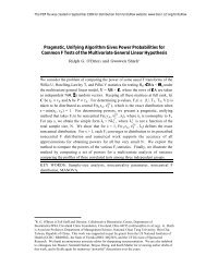
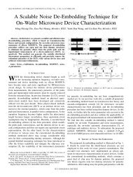
IEEE MICROWAVE AND WIRELESS COMPONENTS LETTERS, VOL. 13, NO. 12, DECEMBER 2003 517<br />
A Novel Coupling Structure Suitable<br />
<strong>for</strong> Cross-Coupled Filters With<br />
Folded Quarter-Wave Resonators<br />
Chi-Yang Chang and Cheng-Chung Chen<br />
Abstract—A new class of <strong>coupling</strong> <strong>structure</strong> <strong>for</strong> <strong>cross</strong>-<strong>coupled</strong><br />
<strong>filters</strong> <strong>with</strong> folded quarter-wave resonators is presented. The<br />
<strong>cross</strong> <strong>coupling</strong> mechanism is realized by magnetic <strong>coupling</strong> from<br />
the short ends of the resonator. The proposed magnetic <strong>coupling</strong><br />
solves the problem of response limitation of folded quarter-wave<br />
resonator <strong>cross</strong>-<strong>coupled</strong> <strong>filters</strong> that were introduced previously<br />
using electrical <strong>cross</strong> <strong>coupling</strong>. Several quadruplet and trisection<br />
<strong>filters</strong> are proposed and fabricated. The measured results matched<br />
well <strong>with</strong> the theoretical prediction.<br />
Index Terms—Cross-<strong>coupled</strong> filter, magnetic <strong>cross</strong> <strong>coupling</strong>,<br />
quarter-wave resonator.<br />
I. INTRODUCTION<br />
RECENTLY, several compact microstrip <strong>cross</strong>-<strong>coupled</strong><br />
filter configurations have been proposed [1]–[7]. While<br />
most of reported literatures use half-wave resonators [1]–[4],<br />
some use quarter-wave resonators [5]–[7] that have advantage<br />
on size reduce of the filter and stop-band rejection. In [6],<br />
[7], the planar <strong>cross</strong>-<strong>coupled</strong> <strong>filters</strong> realize the electrical <strong>cross</strong><br />
<strong>coupling</strong> by bending the open end of quarter-wave or folded<br />
quarter-wave resonators. The various responses of the <strong>filters</strong><br />
are achieved by alter one of the resonator in main <strong>coupling</strong> path<br />
to cause 180 phase difference. Among those quarter-wave<br />
resonator <strong>filters</strong>, the folded quarter-wave resonator filter [6]<br />
has the smallest size. However, <strong>for</strong> the folded quarter-wave<br />
resonator filter, the use of the open-end electrical <strong>coupling</strong><br />
proposed in [6] have following shortcomings. Firstly, in order<br />
to obtain the flat group delay response, the quadruplet filter<br />
needs to reverse the second or the third resonator and leads to<br />
an asymmetric layout that makes filter design more complex.<br />
Moreover, in the case of trisection <strong>filters</strong> to be presented in this<br />
paper, if the electrical-<strong>cross</strong>-<strong>coupling</strong> is applied, the filter can<br />
have a transmission zero only at the lower stop-band. It is not<br />
possible to realize an upper stop-band transmission zero by<br />
reversing the second resonator in the trisection filter. To solve<br />
these problems, a <strong>novel</strong> magnetic <strong>coupling</strong> <strong>structure</strong> <strong>suitable</strong><br />
<strong>for</strong> <strong>cross</strong>-<strong>coupled</strong> filter <strong>with</strong> folded quarter-wave resonators as<br />
shown in Fig. 1 and 2 is proposed in this paper. In Fig. 1(b) and<br />
Fig. 2(b), the <strong>cross</strong> <strong>coupling</strong> is achieved by magnetic <strong>coupling</strong><br />
Manuscript received February 21, 2003; revised July 13, 2003. This work<br />
was supported in part by National Science Council under Grant NSC90-2213-<br />
E009-055 and by the Ministry of Education under Grant 89-E-FA06-2-4. The<br />
review of this letter was arranged by Associate Editor Dr. Shigeo Kawasaki.<br />
The authors are <strong>with</strong> the Institute of Electrical Communication Engineering,<br />
National Chiao Tung University, Hsinchu 300, Taiwan, R.O.C.<br />
Digital Object Identifier 10.1109/LMWC.2003.819957<br />
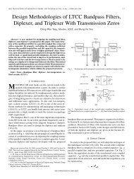
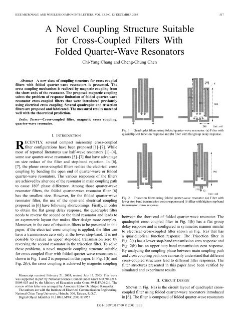
Fig. 1. Quadruplet <strong>filters</strong> using folded quarter-wave resonator. (a) Filter <strong>with</strong><br />
quasielliptical function response and (b) filter <strong>with</strong> flat group delay response.<br />
Fig. 2. Trisection <strong>filters</strong> using folded quarter-wave resonator. (a) Filter <strong>with</strong><br />
lower stop band transmission zeros response and (b) filter <strong>with</strong> higher stop band<br />
transmission zeros response.<br />
between the short-end of folded quarter-wave resonator. The<br />
quadruplet <strong>cross</strong>-<strong>coupled</strong> filter in Fig. 1(b) has a flat group<br />
delay response and is configured in symmetric manner similar<br />
to electrical <strong>cross</strong>-<strong>coupled</strong> filter shown in Fig. 1(a) that has<br />
a quasielliptical function response. The Trisection filter in<br />
Fig. 2(a) has a lower stop-band transmission zero response and<br />
Fig. 2(b) has an upper stop-band transmission zero response.<br />
By analyzing the <strong>coupling</strong> phase between main <strong>coupling</strong> path<br />
and <strong>cross</strong> <strong>coupling</strong> path, one can easily understand that different<br />
<strong>cross</strong>-<strong>coupled</strong> <strong>structure</strong>s lead to different filter responses. The<br />
filter <strong>structure</strong>s presented in this paper have been verified by<br />
simulated and experiment results.<br />
II. CIRCUIT DESIGN<br />
Shown in Fig. 1(a) is the circuit layout of quadruplet <strong>cross</strong><strong>coupled</strong><br />
filter using folded quarter-wave resonators introduced<br />
in [6]. The filter is composed of folded quarter-wave resonators<br />
1531-1309/03$17.00 © 2003 IEEE
518 IEEE MICROWAVE AND WIRELESS COMPONENTS LETTERS, VOL. 13, NO. 12, DECEMBER 2003<br />
TABLE I<br />
DESIGN PARAMETERS FOR QUADRUPLET AND TRISECTION<br />
CROSS-COUPLED FILTER<br />
in comb-type <strong>coupling</strong> and the <strong>cross</strong> <strong>coupling</strong> is realized by the<br />
electrical <strong>coupling</strong> from the open end of first and fourth resonators.<br />
According to the analysis in [6], the filter has quasielliptical<br />
function response. In Fig. 1(b), a new <strong>structure</strong> of quadruplet<br />
filter similar to Fig. 1(a) is proposed except that the <strong>cross</strong><br />
<strong>coupling</strong> between first and fourth resonator is achieved by magnetic<br />
<strong>coupling</strong> between short ends of resonators. As shown in<br />
Fig. 1(b), a short high impedance line connects two resonators<br />
at proper position near two short ends. The specified strength of<br />
<strong>cross</strong> <strong>coupling</strong> can be realized by appropriately adjust the distance<br />
between this high impedance line and two short ends. If<br />
this high impedance line is omitted, the magnetic <strong>cross</strong> <strong>coupling</strong><br />
could be too weak to realize enough <strong>coupling</strong> strength. The magnetic<br />
<strong>cross</strong> <strong>coupling</strong> in Fig. 1(b) shows 180 phase difference to<br />
the electrical <strong>cross</strong> <strong>coupling</strong> in Fig. 1(a) at both frequency range<br />
and . As a result, the filter response changes from<br />
quasielliptical function to flat group delay.<br />
The trisection <strong>filters</strong> using folded quarter-wave resonator is<br />
shown in Fig. 2. The first and second resonators of the <strong>filters</strong><br />
are <strong>coupled</strong> by comb-type <strong>coupling</strong> and the second and third by<br />
interdigital-type. The filter in Fig. 2(a) has a transmission zero at<br />
lower stop-band as a result of electrical <strong>cross</strong> <strong>coupling</strong> through<br />
the open ends of first and third folded quarter-wave resonators.<br />
On the contrary, the filter in Fig. 2(b) has an upper stop band<br />
transmission zero as a result of magnetic <strong>cross</strong> <strong>coupling</strong>. Note<br />
the layout of magnetic <strong>cross</strong> <strong>coupling</strong> in Fig. 2(b) is different<br />
from that in Fig. 1(b). It is because the desired strength of <strong>cross</strong><br />
<strong>coupling</strong> <strong>for</strong> trisection filter is larger than quadruplet filter on<br />
condition that both <strong>filters</strong> have same position of transmission<br />
zero. To achieve this, layout <strong>with</strong> larger magnetic <strong>coupling</strong> is<br />
proposed as shown in Fig. 2(b). In Fig. 2(b), the first and third<br />
resonators are shorted to grounding via a common transmission<br />
line. The transmission line served as a mutually <strong>coupled</strong> inductors<br />
and the length of the line determine the strength of the magnetic<br />
<strong>cross</strong> <strong>coupling</strong>. The method proposed in [6], [7] to analyze<br />
the phase difference between main <strong>coupling</strong> and <strong>cross</strong> <strong>coupling</strong><br />
path can be used to analyze the stop-band behavior of the proposed<br />
<strong>cross</strong>-<strong>coupled</strong> <strong>filters</strong>. Let us concentrate our attention to<br />
newly proposed <strong>structure</strong> Figs. (1b) and (2b). After the <strong>coupling</strong><br />
phases along main <strong>coupled</strong> and <strong>cross</strong> <strong>coupled</strong> path are studied<br />
and added up, the simulated results demonstrate that the filter<br />
in Fig. 1(b) has 0 phase difference between main <strong>coupling</strong> and<br />
<strong>cross</strong> <strong>coupling</strong> at both frequency range and . Con-<br />
(a)<br />
(b)<br />
Fig. 3. Coupling <strong>structure</strong>s and design curve <strong>for</strong> magnetic <strong>cross</strong> <strong>coupling</strong>.<br />
(a) Fig. 1(b) and (b) Fig. 2(b).<br />
sequently, the filter <strong>with</strong> flat-group delay response is realized.<br />
With the same procedure, we conclude the phase difference between<br />
the main <strong>coupling</strong> path and the <strong>cross</strong> <strong>coupling</strong> path of the<br />
trisection filter in Fig. 2(b) is 0 <strong>for</strong> and 180 <strong>for</strong> .<br />
Thus, the filter has the response <strong>with</strong> a transmission zero at the<br />
upper stop-band.<br />
III. DESIGN EXAMPLES<br />
To verify the proposed filter configurations, the quadruplet<br />
filter in Fig. 1(b) and trisection filter in Fig. 2(b) are designed.<br />
The physical parameters are obtained by determining the <strong>coupling</strong><br />
coefficients between resonators and external quality factor<br />
using a full-wave EM simulator from Sonnet [8]. The <strong>coupling</strong><br />
coefficients are synthesized following the method described in<br />
[9], [10] and listed in Table I. The <strong>coupling</strong> coefficient of electrical<br />
<strong>cross</strong> <strong>coupling</strong> of the filter in Fig. 2(a) is achieved by<br />
determining the gap between two open ends of resonators. On
CHANG AND CHEN: NOVEL COUPLING STRUCTURE SUITABLE FOR CROSS-COUPLED FILTERS 519<br />
and Fig. 2(b) respectively. As <strong>for</strong> the external quality factor, the<br />
singly loaded method introduced in [11] is used to determine<br />
the tap-in position of input and output resonators.<br />
The trial <strong>filters</strong> are fabricated on a Rogers RO4003 substrate.<br />
The substrate has a relative dielectric constant of 3.38, a thickness<br />
of 20 mils, and a copper cladding of half an ounce. Fig. 4(a)<br />
shows the measured , and group delay of the <strong>cross</strong><strong>coupled</strong><br />
filter in Fig. 1. Comparing <strong>with</strong> the Chebyshev filter<br />
using folded quarter-wave resonator, this CQ filter shows flat<br />
pass-band group delay characteristics. The measure results of<br />
trisection filter in Fig. 2(b) are shown in Fig. 4(b). The filter has<br />
a higher stop band transmission zero as the results of magnetic<br />
<strong>cross</strong> <strong>coupling</strong>.<br />
(a)<br />
IV. CONCLUSIONS<br />
We have presented a <strong>novel</strong> <strong>coupling</strong> <strong>structure</strong> to realize the<br />
trisection and quadruplet <strong>cross</strong>-<strong>coupled</strong> filter <strong>for</strong>med by folded<br />
quarter-wave resonators. The newly proposed magnetic <strong>coupling</strong><br />
<strong>structure</strong> solves the problem of limitation of response of a<br />
trisection filter and layout symmetry of a quadruplet filter. Either<br />
open end or short end of the folded quarter-wave resonators<br />
can be bent to achieve <strong>cross</strong> <strong>coupling</strong>. With this newly proposed<br />
<strong>cross</strong> <strong>coupling</strong> <strong>structure</strong>, a designer has larger degree of freedom<br />
to design a CT or CQ <strong>cross</strong>-<strong>coupled</strong> filter.<br />
(b)<br />
Fig. 4. (a) Measured results of quadruplet filter <strong>with</strong> flat group delay response<br />
in Fig. 1(a) and Chebyshev filter. (b) Measured and simulated results of<br />
trisection filter in Fig. 2(b).<br />
the other hand, the <strong>coupling</strong> coefficient of magnetic <strong>cross</strong> <strong>coupling</strong><br />
of the filter in Fig. 1(b) is achieved by determining the<br />
distance between the high impedance connecting line and two<br />
short ends. In Fig. 2(b), the length of common transmission line<br />
connected to grounding determines the <strong>coupling</strong> coefficient of<br />
magnetic <strong>cross</strong> <strong>coupling</strong> of the filter. Fig. 3(a) and Fig. 3(b)<br />
present the design curves and physical parameters <strong>for</strong> the determination<br />
of magnetic <strong>coupling</strong> coefficients of the <strong>filters</strong> in Fig. 1<br />
REFERENCES<br />
[1] P. L. Field, I. C. Hinter, and J. G. Gardiner, “Asymmetric bandpass filter<br />
using a <strong>novel</strong> microstrip <strong>structure</strong>,” IEEE Microwave Guided Wave Lett.,<br />
vol. 2, pp. 247–249, June 1992.<br />
[2] J. S. Hong and M. J. Lancaster, “Theory and experiment of <strong>novel</strong> microstrip<br />
slow-wave open-loop resonator <strong>filters</strong>,” IEEE Trans. Microwave<br />
Theory Tech, vol. 45, pp. 2358–2365, Dec. 1997.<br />
[3] , “Cross-<strong>coupled</strong> microstrip hairpin-resonator <strong>filters</strong>,” IEEE Trans.<br />
Microwave Theory Tech., vol. 46, pp. 118–122, Jan. 1998.<br />
[4] , “Microstrip <strong>cross</strong>-<strong>coupled</strong> trisection bandpass <strong>filters</strong> <strong>with</strong><br />
asymmetric frequency characteristics,” IEE Proc. Microw. Antenna<br />
Propagat., vol. 146, no. 1, Feb. 1999.<br />
[5] S. J. Yao, R. R. Bonetti, and A. E. Williams, “Generalized dual-plane<br />
multi<strong>coupled</strong> line <strong>filters</strong>,” IEEE Trans. Microwave Theory Tech., vol.<br />
41, pp. 2182–2189, Dec. 1993.<br />
[6] C. Y. Chang, C. C. Chen, and H. J. Huang, “Folded quarter-wave resonator<br />
filter <strong>with</strong> Chebyshev, flat group delay and quasielliptical function<br />
response,” in IEEE MTT-S Dig., 2002, pp. 1609–1612.<br />
[7] C. C. Chen, Y. R. Chen, and C. Y. Chang, “Miniaturized microstrip<br />
<strong>cross</strong>-<strong>coupled</strong> <strong>filters</strong> using quarter-wave or quasiquarter-wave resonators,”<br />
IEEE Trans. Microwave Theory Tech., vol. 51, pp. 120–131,<br />
Jan. 2003.<br />
[8] Sonnet 6.0a, Sonnet Software, Inc.<br />
[9] R. Levy, “Direct synthesis of cascaded quadruplet (CQ) <strong>filters</strong>,” IEEE<br />
Trans. Microwave Theory Tech., vol. 43, pp. 2940–2945, Dec. 1995.<br />
[10] R. J. Cameron, “Fast generation of Chebyshev filter prototypes <strong>with</strong><br />
asymmetrically-prescribed transmission zeros,” ESA J., vol. 6, no. 1, pp.<br />
83–95, 1982.<br />
[11] R. S. Kwok and J. F. Liang, “Characterization of high-Q resonators <strong>for</strong><br />
microwave-filter application,” IEEE Trans. Microwave Theory Tech.,<br />
vol. 47, pp. 111–114, Jan. 1999.