A Scalable Noise De-Embedding Technique for On ... - IEEE Xplore
A Scalable Noise De-Embedding Technique for On ... - IEEE Xplore
A Scalable Noise De-Embedding Technique for On ... - IEEE Xplore

You also want an ePaper? Increase the reach of your titles
YUMPU automatically turns print PDFs into web optimized ePapers that Google loves.
<strong>IEEE</strong> MICROWAVE AND WIRELESS COMPONENTS LETTERS, VOL. 15, NO. 10, OCTOBER 2005 649<br />
A <strong>Scalable</strong> <strong>Noise</strong> <strong>De</strong>-<strong>Embedding</strong> <strong>Technique</strong> <strong>for</strong><br />
<strong>On</strong>-Wafer Microwave <strong>De</strong>vice Characterization<br />
Ming-Hsiang Cho, Guo-Wei Huang, Member, <strong>IEEE</strong>, Yueh-Hua Wang, and Lin-Kun Wu, Member, <strong>IEEE</strong><br />
Abstract—In this letter, we present a scalable and efficient noise<br />
de-embedding procedure, which is based on transmission-line<br />
theory and cascade configurations, <strong>for</strong> on-wafer microwave measurements<br />
of silicon MOSFETs. The proposed de-embedding<br />
procedure utilizes one open and one thru dummy structures<br />
to eliminate the parasitic effects from the probe pads and the<br />
input/output interconnects of a device-under-test (DUT), respectively.<br />
This method can generate the scalable distributed<br />
interconnect parameters to efficiently and precisely remove the<br />
redundant parasitics of the DUTs with various device sizes and<br />
arbitrary interconnect dimensions.<br />
Index Terms—Calibration, de-embedding, MOSFET, noise,<br />
-parameters.<br />
I. INTRODUCTION<br />
WITH the downscaling device channel length as well<br />
as the increasing operation frequency, on-wafer measurement<br />
and device modeling work on silicon MOSFETs<br />
have become more and more significant <strong>for</strong> RF/microwave<br />
circuit design. To extract the intrinsic device per<strong>for</strong>mance<br />
from measurements, the unnecessary parasitics of the probe<br />
pads and input/output interconnects must be exactly removed<br />
from the measured data. In previous literature [1]–[3], several<br />
parasitic de-embedding methods based on physical equivalent-circuit<br />
models have been developed and extensively<br />
utilized over the past decade. These physics-based methods<br />
treat the device-under-test (DUT) as an intrinsic device connected<br />
to the external parasitics, which come from the probe<br />
pads and interconnects, in parallel-series configurations. As the<br />
operation frequency becomes higher and/or the interconnect<br />
length becomes longer, nevertheless, these equivalent-circuit<br />
assumptions may be inappropriate. Recently, a cascade-based<br />
de-embedding scheme [4] has been presented, which models<br />
the probe pads, interconnects, and the intrinsic device in cascade<br />
configurations and does not require any equivalent-circuit<br />
representation. <strong>On</strong> the other hand, <strong>for</strong> the characterization<br />
of devices in various sizes, the conventional de-embedding<br />
methods mentioned above may occupy considerable chip<br />
area <strong>for</strong> their corresponding dummy structures. Although the<br />
ground-shielded measuring technique has been introduced to<br />
offer the fixture scalability and mitigate the chip-area consumption<br />
[5], the scalability of the interconnect parameters<br />
Manuscript received March 2, 2005; revised May 25, 2005. The review of<br />
this letter was arranged by Associate Editor F. Ellinger.<br />
M. H. Cho and G.-W. Huang are with National Nano <strong>De</strong>vice Laboratories,<br />
Hsinchu 300, Taiwan, R.O.C. (e-mail: mhcho@mail.ndl.org.tw).<br />
Y.-H. Wang and L.-K. Wu are with the <strong>De</strong>partment of Communication Engineering,<br />
National Chiao Tung University, Hsinchu 300, Taiwan, R.O.C.<br />
Digital Object Identifier 10.1109/LMWC.2005.856685<br />
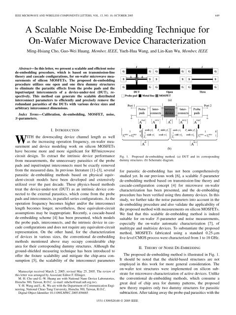
Fig. 1. Proposed de-embedding method. (a) DUT and its corresponding<br />
dummy structures. (b) Schematic diagram.<br />
<strong>for</strong> parasitic de-embedding has not been comprehensively<br />
studied yet. In our previous work [6], a scalable -parameter<br />
de-embedding method based on transmission-line theory and<br />
cascade-configuration concept [4] <strong>for</strong> microwave on-wafer<br />
characterization has been presented, and the de-embedding<br />
procedure has been verified using thru dummy devices. In this<br />
study, we further take the noise parameters into account in the<br />
de-embedding procedure and also validate the applicability of<br />
the proposed method with measurements on silicon MOSFETs.<br />
We find that this scalable de-embedding method is indeed<br />
suitable <strong>for</strong> on-wafer -parameter and noise measurements,<br />
especially the on-wafer automatic characterization [7], of<br />
multitype and multisize devices. To substantiate the proposed<br />
method, MOSFETs fabricated using a standard 0.25- m<br />
five-level CMOS process were characterized from 1 to 18 GHz.<br />
II. THEORY OF NOISE DE-EMBEDDING<br />
The proposed de-embedding method is illustrated in Fig. 1.<br />
It should be noted that the shield-based structures are not<br />
employed in this work <strong>for</strong> more general consideration. The<br />
on-wafer test structures were implemented on silicon substrate<br />
<strong>for</strong> microwave characterization of active devices. Unlike<br />
the conventional de-embedding methods, which consume a<br />
great deal of chip area <strong>for</strong> dummy patterns, the proposed<br />
new theory requires only two dummy structures <strong>for</strong> parasitic<br />
subtraction. After taking away the probe-pad parasitics with the<br />
1531-1309/$20.00 © 2005 <strong>IEEE</strong>
650 <strong>IEEE</strong> MICROWAVE AND WIRELESS COMPONENTS LETTERS, VOL. 15, NO. 10, OCTOBER 2005<br />
open dummy, the per-unit-length transmission-line parameters<br />
of the thru dummy can be evaluated [6]. Then, DUTs with<br />
various device sizes and interconnect lengths can be individually<br />
de-embedded with the application of the interconnect<br />
scalability.<br />
Similar to the conventional cascade-based method [4],<br />
a thru device can be simply modeled in cascade connection.<br />
After de-embedding the pad parasitics from<br />
and converting<br />
the chain matrix to its -parameter matrix<br />
, where the superscript “ ” denotes the inverse of the<br />
matrix and , , and are, respectively,<br />
the chain matrices of the intrinsic interconnects,<br />
probe pads, and thru dummy, the interconnect characteristic<br />
impedance and propagation constant can be calculated as<br />
[8]<br />
and<br />
where is the impedance of the -parameter measurement<br />
system, is the interconnect length, and<br />
For the extraction of and , the “ ” signs in (1) and (2)<br />
are used to correct the unreasonable solutions, such as negative<br />
attenuation constants [8].<br />
Based on the above results, the chain matrices of the<br />
input and output interconnects with arbitrary line lengths can be<br />
generated by respectively substituting the interconnect lengths<br />
and into the chain matrix of a lossy transmission<br />
line as<br />
(1)<br />
(2)<br />
(3)<br />
5) Convert to its -parameter matrix and<br />
calculate the interconnect characteristic impedance<br />
and propagation constant based on (1) and (2).<br />
6) Create the chain matrices and<br />
of the input and output interconnects by, respectively,<br />
substituting the interconnect lengths and into (4).<br />
7) Calculate the chain matrices of the input port<br />
and the output port using<br />
and<br />
, respectively.<br />
8) Convert to its chain matrix and<br />
calculate the chain matrix of the intrinsic<br />
device using .<br />
9) Convert to , where is the intrinsic scattering<br />
matrix of the DUT.<br />
10) Convert and to their impedance matrices<br />
and , respectively.<br />
11) Calculate the noise correlation matrices<br />
and from and<br />
, respectively, where is<br />
the Boltzmann’s constant and is the absolute temperature.<br />
12) Convert and to their chain matrices<br />
and using<br />
and<br />
, respectively, where the superscript<br />
“ ” denotes the Hermitian conjugate of the matrix, and<br />
the trans<strong>for</strong>mation matrix and are<br />
and<br />
13) Calculate the intrinsic correlation matrix<br />
[9].<br />
14) Calculate the intrinsic noise parameters , , and<br />
from the noise correlation matrix using<br />
(6)<br />
(7)<br />
(4)<br />
The proposed -parameter and noise de-embedding procedure<br />
based on cascade connection is listed as follows.<br />
1) Measure the scattering parameters , ,<br />
and of the DUT, open, and thru, respectively.<br />
2) Measure the noise parameters , , and<br />
of the DUT and calculate the correlation matrix<br />
[9].<br />
3) Convert to its admittance matrix and<br />
calculate the chain matrix of the probe<br />
pads from<br />
4) Calculate the intrinsic interconnect parameters using<br />
.<br />
(5)<br />
and<br />
III. RESULTS AND DISCUSSION<br />
(8)<br />
(9)<br />
(10)<br />
The on-wafer -parameter and noise measurements were<br />
per<strong>for</strong>med with ATN NP5B <strong>Noise</strong> Parameter Measurement<br />
System. To validate the proposed scalable de-embedding procedure<br />
<strong>for</strong> active devices, three n-MOSFETs with the same<br />
device dimensions and various interconnect lengths between
CHO et al.: SCALABLE NOISE DE-EMBEDDING TECHNIQUE 651<br />
optimized input reflection coefficient versus frequency<br />
characteristics of the three MOSFETs biased at 1.5 V<br />
and 1.15 V. These results indicate that the intrinsic<br />
noise parameters obtained from the conventional cascade-based<br />
method [4] and proposed method are in good agreement over<br />
the entire frequency range. Fig. 3 exhibits the measured and<br />
de-embedded noise parameters versus drain current characteristics<br />
of the three MOSFETs at 18 GHz. The interconnects at<br />
input port of LS are longer than those of SL and SS and thus<br />
have more impact on the measured noise parameters. However,<br />
after finishing the noise de-embedding, the intrinsic noise<br />
parameters of the three MOSFETs obtained from the conventional<br />
cascade-based method and proposed scalable method<br />
are approximately the same. Based on the above findings, we<br />
can use this proposed de-embedding method instead of the<br />
conventional one to efficiently calculate the intrinsic noise<br />
parameters of the MOSFETs.<br />
Fig. 2. <strong>Noise</strong> parameters versus frequency characteristics (a) NF , (b) R ,<br />
(c) j0 j, and (d) 0 of three different n-MOSFETs—LS, SL, and<br />
SS obtained from measurement results (lines), conventional de-embedding<br />
method (open symbols), and proposed de-embedding method (solid symbols).<br />
The DUTs are biased at V = 1.5 V and V = 1.15 V (I = 13.3 mA).<br />
Fig. 3. <strong>Noise</strong> parameters versus drain current characteristics (a) NF ,<br />
(b) R , (c) j0 j, and (d) 0 of three different n-MOSFETs obtained<br />
from measurement results (lines), conventional method (open symbols), and<br />
proposed method (solid symbols) at 18 GHz. The DUTs are biased at V =<br />
1.5 V and I = 1–30 mA.<br />
the probe pads and DUT—LS ( 200 m, 20 m),<br />
SL ( 20 m, 200 m), and SS ( 20 m,<br />
20 m), and their corresponding dummy structures were<br />
designed and fabricated. The channel length and width of<br />
the n-MOSFET are 0.24 and 110 m (10 m 11), respectively.<br />
The interconnect width and the dimensions of probe<br />
pads are 10 and 70 m 70 m, respectively. Fig. 2 shows<br />
the measured and de-embedded noise parameters—minimum<br />
noise figure , equivalent noise resistance , and<br />
IV. CONCLUSION<br />
In this study, a general noise de-embedding method suitable<br />
<strong>for</strong> on-wafer device characterization has been presented and<br />
verified with various devices. This method requires only one<br />
open and one thru dummy structures to generate the scalable<br />
and repeatable interconnect parameters <strong>for</strong> parasitic subtraction.<br />
There<strong>for</strong>e, the consumption of chip area <strong>for</strong> dummy structures<br />
can be minimized. Compared with the conventional cascadebased<br />
method, the proposed one can eliminate the unwanted parasitics<br />
of the DUTs more efficiently.<br />
REFERENCES<br />
[1] M. C. A. M. Koolen, J. A. M. Geelen, and M. P. J. G. Versleijen, “An<br />
improved de-embedding technique <strong>for</strong> on-wafer high-frequency characterization,”<br />
in Proc. <strong>IEEE</strong> Bipolar Circuits Technol. Meeting, 1991, pp.<br />
188–191.<br />
[2] H. Cho and D. E. Burk, “A three-step method <strong>for</strong> the de-embedding<br />
of high-frequency S-parameter measurements,” <strong>IEEE</strong> Trans. Electron<br />
<strong>De</strong>vices, vol. 38, no. 6, pp. 1371–1371, Jun. 1991.<br />
[3] T. E. Kolding, “A four-step method <strong>for</strong> de-embedding gigahertz<br />
on-wafer CMOS measurements,” <strong>IEEE</strong> Trans. Electron <strong>De</strong>vices, vol.<br />
47, no. 4, pp. 734–740, Apr. 2000.<br />
[4] C. H. Chen and M. J. <strong>De</strong>en, “A general noise and S-parameter deembedding<br />
procedure <strong>for</strong> on-wafer high-frequency noise measurements<br />
of MOSFETs,” <strong>IEEE</strong> Trans. Microw. Theory Tech., vol. 49, no. 5, pp.<br />
1004–1004, May 2001.<br />
[5] T. E. Kolding, “Shield-based microwave on-wafer device measurements,”<br />
<strong>IEEE</strong> Trans. Microw. Theory Tech., vol. 49, no. 6, pp.<br />
1039–1039, Jun. 2001.<br />
[6] M. H. Cho, G. W. Huang, K. M. Chen, and A. S. Peng, “A novel cascadebased<br />
de-embedding method <strong>for</strong> on-wafer microwave characterization<br />
and automatic measurement,” in <strong>IEEE</strong> MTT-S Int. Dig., Jun. 2004, pp.<br />
1237–1240.<br />
[7] G. W. Huang, D. Y. Chiu, K. M. Chen, Y. M. <strong>De</strong>ng, and S. C. Wang, “An<br />
automatic program suitable <strong>for</strong> on-wafer characterization, and statistic<br />
analysis of microwave devices,” in 61st ARFTG Conf. Dig., Jun. 2003,<br />
pp. 157–161.<br />
[8] W. R. Eisenstadt and Y. Eo, “S-parameter-based IC interconnect transmission<br />
line characterization,” <strong>IEEE</strong> Trans. Compon., Hybrids, Manufact.<br />
Technol., vol. 15, no. 5, pp. 483–483, Aug. 1992.<br />
[9] H. Hillbrand and P. H. Russer, “An efficient method <strong>for</strong> computer-aided<br />
noise analysis of linear amplifier networks,” <strong>IEEE</strong> Trans. Circuits Syst.,<br />
vol. CAS-23, no. 4, pp. 235–235, Apr. 1976.