- Page 1 and 2: Anne Arundel County, Maryland Depar
- Page 3 and 4: SPECIFICATIONS TABLE OF CONTENTS DI
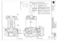
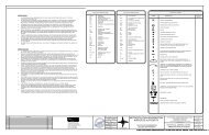
- Page 5 and 6: SECTION 00850 - DRAWING LIST G100-C
- Page 7 and 8: E0.1-Electrical Cover Sheet E1.1-Si
- Page 9 and 10: SECTION 15055 - COMMON MOTOR REQUIR
- Page 11 and 12: 5 89.5 7 1/2 91.0 10 91.7 15 92.4 2
- Page 13 and 14: SECTION 15050 - COMMON WORK RESULTS
- Page 15 and 16: free”, containing not more than 0
- Page 17 and 18: label, as a complete packaged syste
- Page 19 and 20: H. Visual Matching Specification: W
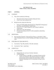
- Page 21 and 22: D. Erection of Metal Supports and A
- Page 23 and 24: D. Remove all construction marking
- Page 25 and 26: D. Provide at least 8 hours straigh
- Page 27 and 28: SECTION 15051 - COMMON WORK RESULTS
- Page 29: 1. Record Drawings: Prepare record
- Page 33 and 34: E. Products specified by Naming Pro
- Page 35 and 36: B. Rough-In required to be installe
- Page 37 and 38: 3.7 CLEANING A. Clean surfaces prio
- Page 39 and 40: 2. Training period shall be perform
- Page 41 and 42: SECTION 15060 - HANGERS AND SUPPORT
- Page 43 and 44: A. General: Submit the following ac
- Page 45 and 46: D. Grout: ASTM C 1107, Grade B, “
- Page 47 and 48: T. Horizontal AWWA Piping (Flanged
- Page 49 and 50: Nom. Pipe Size - In. Steel Pipe Max
- Page 51 and 52: E. Adjust storm collars tight to pi
- Page 53 and 54: SECTION 15061 - HANGERS AND SUPPORT
- Page 55 and 56: A. Terminology used in this Section
- Page 57 and 58: A. Structural Steel: ASTM A 36/A 36
- Page 59 and 60: 2.3 ACOUSTICAL SEALANT A. Sealants
- Page 61 and 62: Nom. Pipe Size - In. Steel Pipe Max
- Page 63 and 64: SECTION 15071 - VIBRATION AND SEISM
- Page 65 and 66: f. Additional deflection to solid u
- Page 67 and 68: 2.1 MATERIALS A. Structural Steel:
- Page 69 and 70: C. Bases 1. Squarely align vibratio
- Page 71 and 72: SECTION 15072 - VIBRATION AND SEISM
- Page 73 and 74: B. Welder certificates signed by Co
- Page 75 and 76: B. Installer: Company specializing
- Page 77 and 78: Pump bases for split case pump shal
- Page 79 and 80: 2.8 GROMMETS movement during starti
- Page 81 and 82:
isolation system. D. Flexible Duct
- Page 83 and 84:
SECTION 15075 - IDENTIFICATION FOR
- Page 85 and 86:
2. Stencil Paint: Standard exterior
- Page 87 and 88:
3.2 INSTALLATION: A. General: 1. Co
- Page 89 and 90:
SECTION 15076 - IDENTIFICATION FOR
- Page 91 and 92:
B. Painted Identification Materials
- Page 93 and 94:
3.2 INSTALLATION A. General: 1. Coo
- Page 95 and 96:
SECTION 15080 - MECHANICAL INSULATI
- Page 97 and 98:
A. Insulate heating system pumps an
- Page 99 and 100:
smoothing coat of insulating cement
- Page 101 and 102:
SECTION 15105 - PIPES AND TUBES FOR
- Page 103 and 104:
24. ANSI/AWA C606, “Grooved and S
- Page 105 and 106:
5. ANSI/AWWA C110, “American Nati
- Page 107 and 108:
1.9 FIELD MEASUREMENTS A. Verify fi
- Page 109 and 110:
C. Plastic Pipe Flange Gasket, Bolt
- Page 111 and 112:
membrane clamps, adjustable type 'B
- Page 113 and 114:
h. Stem: Copper-plated steel, alumi
- Page 115 and 116:
shall be provided and firestopped u
- Page 117 and 118:
B. Joint Construction installed thr
- Page 119 and 120:
1. General: Install flow meters for
- Page 121 and 122:
B. General 3. Install sleeve and me
- Page 123 and 124:
D. Protection not smaller than requ
- Page 125 and 126:
2. Use ambient temperature water as
- Page 127 and 128:
SECTION 15106 - PIPES AND TUBES FOR
- Page 129 and 130:
and Pipe Fittings,” 2004. 6. ASTM
- Page 131 and 132:
1. ASME B31.9, “Building Services
- Page 133 and 134:
1. ASTM B16, metallic, raised face,
- Page 135 and 136:
N. Pipe Guides: thermoplastic linin
- Page 137 and 138:
1. Provide as manufactured by Badge
- Page 139 and 140:
2.3 SLEEVE PENETRATION SYSTEMS d. T
- Page 141 and 142:
connection of strainer. 11. Anchor
- Page 143 and 144:
e. At inlet and outlet of each ther
- Page 145 and 146:
3.8 FIELD QUALITY CONTROL A. Testin
- Page 147 and 148:
SECTION 15110 - GENERAL DUTY VALVES
- Page 149 and 150:
A. General: Submit each item in thi
- Page 151 and 152:
Milwaukee Model: F-2974 2. Ball Val
- Page 153 and 154:
stem, PTFE seats, PTFE packing, & B
- Page 155 and 156:
E. Examine mating flange faces for
- Page 157 and 158:
3.6 ADJUSTING VALVES specified in D
- Page 159 and 160:
SECTION 15111 - GENERAL DUTY VALVES
- Page 161 and 162:
C. Manufacturer's Installation Inst
- Page 163 and 164:
Other manufacturers: Hammond, Lunke
- Page 165 and 166:
1. Provide as manufactured by Watts
- Page 167 and 168:
C. Operate valves from fully open t
- Page 169 and 170:
SECTION 15127 - EXPANSION FITTINGS
- Page 171 and 172:
experience. 1.9 DELIVERY, STORAGE,
- Page 173 and 174:
anticipated change in temperature.
- Page 175 and 176:
SECTION 15184 - REFRIGERANT PIPING
- Page 177 and 178:
B. Globe: 450 psig maximum operatin
- Page 179 and 180:
evaporators, and elsewhere in accor
- Page 181 and 182:
U. Install moisture/liquid indicato
- Page 183 and 184:
1. Install core in filter dryer aft
- Page 185 and 186:
SECTION 15400 - PLUMBING EQUIPMENT
- Page 187 and 188:
C. American Society of Mechanical E
- Page 189 and 190:
P-2A Urinal (Handicapped): Provide
- Page 191 and 192:
B. Vacuum breakers not subject to b
- Page 193 and 194:
A. Examine roughing-in for potable
- Page 195 and 196:
1. Piping installation requirements
- Page 197 and 198:
SECTION 15600 - HEATING, VENTILATIN
- Page 199 and 200:
5. Installation, Operation and Main
- Page 201 and 202:
I. Refrigeration System a. Coils sh
- Page 203 and 204:
2. Unit shall include a clogged fil
- Page 205 and 206:
duct static pressure sensor. 8. (RT
- Page 207 and 208:
products as manufactured by Taco sh
- Page 209 and 210:
8. Wiring Pigtail: a. Direct hook-u
- Page 211 and 212:
D. All wiring shall be in accordanc
- Page 213 and 214:
2. The outdoor unit shall be capabl
- Page 215 and 216:
sensor, return water temperature se
- Page 217 and 218:
3.3 CONTROL WIRING INSTALLATION A.
- Page 219 and 220:
SECTION 15725 - VARIABLE FREQUENCY
- Page 221 and 222:
1. Complete efficiency versus load
- Page 223 and 224:
including physical inspection of th
- Page 225 and 226:
3.6 CLEANING wiring when controller
- Page 227 and 228:
SECTION 15800 - AIR DISTRIBUTION PA
- Page 229 and 230:
5. Where tap sizes of divided flow
- Page 231 and 232:
Supply Air Duct 30 o F to 180 o F 2
- Page 233 and 234:
F. Submit complete information to t
- Page 235 and 236:
F. Wiring 2. Capacity: Provide coil
- Page 237 and 238:
SECTION 15900 - INSTRUMENTATION AND
- Page 239 and 240:
G. BMS Network: The total digital o
- Page 241 and 242:
C. The Building Management System (
- Page 243 and 244:
E. Manufacturer's Certificate: Cert
- Page 245 and 246:
BMS RESPONSIBILITY MATRIX WORK FURN
- Page 247 and 248:
PART 2 PRODUCTS 2.1 GENERAL A. The
- Page 249 and 250:
6. Flash memory for long term data
- Page 251 and 252:
G. The NAC shall have the ability t
- Page 253 and 254:
1. The system will be provided with
- Page 255 and 256:
5. The system shall support object
- Page 257 and 258:
condition. The user must be able to
- Page 259 and 260:
2.14 MODBUS SYSTEM INTEGRATION w. M
- Page 261 and 262:
2. All BMS wiring materials and ins
- Page 263 and 264:
a. Where the stations are installed
- Page 265 and 266:
B. The Division 15 contractor shall
- Page 267 and 268:
3) Return air damper shall be fully
- Page 269 and 270:
a. When the economizer mode is disa
- Page 271 and 272:
e. Heat Recovery Wheel Failure Alar
- Page 273 and 274:
d. Boilers will operate normally un
- Page 275 and 276:
APPARATUS, OR ANALOG GENERAL SUPPLE
- Page 277 and 278:
APPARATUS, OR ANALOG GENERAL INPUT/
- Page 279 and 280:
SUPPLEMENTAL NOTES INPUT/OUTPUT SUM
- Page 281 and 282:
SUPPLEMENTAL NOTES INPUT/OUTPUT SUM
- Page 283 and 284:
SUPPLEMENTAL NOTES INPUT/OUTPUT SUM
- Page 285 and 286:
SECTION 15947 - HVAC PIPING SYSTEMS
- Page 287 and 288:
B. Service Period: Provide chemical
- Page 289 and 290:
PART 3 EXECUTION 3.1 INSTALLATION A
- Page 291 and 292:
SECTION 15948 - PLUMBING PIPING SYS
- Page 293 and 294:
PART 3 EXECUTION 3.1 INSTALLATION A
- Page 295 and 296:
SECTION 15949 - TESTING, ADJUSTING
- Page 297 and 298:
measurement and establishment of fl
- Page 299 and 300:
F. Balancing of domestic hot water
- Page 301 and 302:
SECTION 15950 - TESTING, ADJUSTING
- Page 303 and 304:
1. Employ services of independent t
- Page 305 and 306:
c. Proper direction of rotation for
- Page 307 and 308:
A. In conjunction with “Instrumen
- Page 309 and 310:
SECTION 15955 - LEAK TESTING, AIR D
- Page 311 and 312:
SECTION 16050 - COMMON WORK RESULTS
- Page 313 and 314:
are allowed, unless explicitly stat
- Page 315 and 316:
K. Coordination Drawings: Submit wh
- Page 317 and 318:
g. Time Clocks. h. Panelboards. i.
- Page 319 and 320:
1. Store all materials in dry, heat
- Page 321 and 322:
F. Products specified by Naming One
- Page 323 and 324:
A. Provide tamper proof hardware fo
- Page 325 and 326:
part of the Installer. 3.2 PREPARAT
- Page 327 and 328:
fabrication. F. Cutting and Patchin
- Page 329 and 330:
anch circuit breakers, etc. c. EMS
- Page 331 and 332:
1. Replace any equipment, which fai
- Page 333 and 334:
SHOP DRAWING & PRODUCT DATA SUBMITT
- Page 335 and 336:
SECTION 16060 - GROUNDING AND BONDI
- Page 337 and 338:
C. Bonding Strap Conductor/Connecto
- Page 339 and 340:
c. Provide additional bond to neare
- Page 341 and 342:
olts, in accordance with manufactur
- Page 343 and 344:
1. Make and perform all adjustments
- Page 345 and 346:
SECTION 16120 - LOW VOLTAGE ELECTRI
- Page 347 and 348:
2. XHHW insulation, 90 o C rated. 3
- Page 349 and 350:
2. Straight Splice: To splice under
- Page 351 and 352:
3.3 CONSTRUCTION finished ceiling,
- Page 353 and 354:
SECTION 16130 - RACEWAYS AND BOXES
- Page 355 and 356:
4. Material: Steel only, intermedia
- Page 357 and 358:
1. Steel channels with conduit stra
- Page 359 and 360:
10. 2 - Duplex data RJ45 jacks, Cat
- Page 361 and 362:
3.1 EXAMINATION A. Examine surfaces
- Page 363 and 364:
etween conduit and wall surface. 11
- Page 365 and 366:
F. Use 12" section of wireway to pa
- Page 367 and 368:
SECTION 16140 - WIRING DEVICES PART
- Page 369 and 370:
4. Incandescent, low voltage or flu
- Page 371 and 372:
2.5 DEVICE PLATES & COVERS A. Singl
- Page 373 and 374:
SECTION 16230 - PACKAGED GENERATOR
- Page 375 and 376:
A. Manufacturer’s Requirements: 1
- Page 377 and 378:
4. Pump 4; 3hp, .85pf 5. Pump 5 & 6
- Page 379 and 380:
2.2 RATINGS AND CONDITIONS 2.3 ENGI
- Page 381 and 382:
6. Prototype tested; UL, CSA, and C
- Page 383 and 384:
"Automatic" position. 10. Automatic
- Page 385 and 386:
2.10 EXHAUST SYSTEM 4. CCA rated pe
- Page 387 and 388:
A. As specified in Section "Common
- Page 389 and 390:
1. Provide connections between gene
- Page 391 and 392:
3.7 ADJUSTING 2. A resistive load b
- Page 393 and 394:
SECTION 16440 - LOW VOLTAGE ELECTRI
- Page 395 and 396:
H. Closeout Submittals: Submit in a
- Page 397 and 398:
2.1 MANUFACTURER A. Available Manuf
- Page 399 and 400:
A. UL Listed, automatic circuit bre
- Page 401 and 402:
. Distribution Panels: XDS15 series
- Page 403 and 404:
grounding conductors. 5. Bolt-on br
- Page 405 and 406:
C. Current Transformer Cabinet Inst
- Page 407 and 408:
“Common Work Results For Electric
- Page 409 and 410:
3.7 DEMONSTRATION 6. Remove dirt, d
- Page 411 and 412:
SECTION 16460 - LOW VOLTAGE TRANSFO
- Page 413 and 414:
1. ANSI American National Standards
- Page 415 and 416:
C. Construction (3 kVA through 25 k
- Page 417 and 418:
affected by the work of this sectio
- Page 419 and 420:
SECTION 16480 - LOW VOLTAGE CONTROL
- Page 421 and 422:
1. The complete performance of the
- Page 423 and 424:
2. Manual operated toggle switch ty
- Page 425 and 426:
“Common Work Results For Electric
- Page 427 and 428:
3.9 DEMONSTRATION 4. Remove protect
- Page 429 and 430:
SECTION 16495 - TRANSFER SWITCHES P
- Page 431 and 432:
2. Installer’s pre-startup checkl
- Page 433 and 434:
1. Onan/Cummins(basis of design) 2.
- Page 435 and 436:
3.1 EXAMINATION A. Site Verificatio
- Page 437 and 438:
a. Perform inspections and tests st
- Page 439 and 440:
SECTION 16500 - LIGHTING PART 1 GEN
- Page 441 and 442:
D. Wiring Diagrams: b. Average, max
- Page 443 and 444:
1. Store all fixtures in original p
- Page 445 and 446:
c. Philips Lighting Electronics d.
- Page 447 and 448:
D. Compact Fluorescent Lamp Ballast
- Page 449 and 450:
1. Medium or mogul base to match la
- Page 451 and 452:
e delivered, installed, and operate
- Page 453 and 454:
3.3 CONSTRUCTION A. Grounding: Grou