Volume II (pdf) - Milestone Construction Services, Inc
Volume II (pdf) - Milestone Construction Services, Inc
Volume II (pdf) - Milestone Construction Services, Inc

Create successful ePaper yourself
Turn your PDF publications into a flip-book with our unique Google optimized e-Paper software.
Anne Arundel County, Maryland<br />
Department of Public Works<br />
Bureau of Engineering<br />
Eastern District Police Station<br />
Pasadena Road<br />
Pasadena, Maryland 21122<br />
PROPOSAL # F507600<br />
PROJECT # F507601<br />
Project Manual – <strong>Volume</strong> 2 (Div. 15 & 16)<br />
Architect<br />
WGM Architects<br />
One Annapolis Street, Suite 100<br />
Annapolis, Maryland 21401<br />
(410) 841-6787<br />
(410) 841-5523 (fax)<br />
Civil Engineer<br />
Kibart, <strong>Inc</strong>.<br />
901 Dulaney Valley Road, Suite 300<br />
Towson, Maryland 21204<br />
(401) 494-1111<br />
(401) 494-1112 (fax)<br />
Structural Engineer<br />
The Watkins Partnership<br />
3032 Mitchelville Road, Suite 202<br />
Bowie, MD 20716<br />
(301) 249-0974<br />
(301) 249-0976 (fax)<br />
MEP Engineers<br />
Bay Engineering, <strong>Inc</strong>.<br />
190 Admiral Cochrane Drive, Ste. 175<br />
Annapolis, Maryland 21401<br />
(410) 897-9290<br />
(410) 897-9295 (fax)<br />
Bureau of Engineering<br />
January 15, 2013<br />
WGM Project No. 28103.01
This page intentionally left blank.
SPECIFICATIONS<br />
TABLE OF CONTENTS<br />
DIVISION 0 - GENERAL REQUIREMENTS<br />
Pages<br />
00850 Drawing List 3<br />
DIVISION 1 - GENERAL REQUIREMENTS<br />
Pages<br />
See <strong>Volume</strong> 1<br />
DIVISION 2 – SITE CONSTRUCTION<br />
See <strong>Volume</strong> 1<br />
DIVISION 3 – CONCRETE<br />
See <strong>Volume</strong> 1<br />
DIVISION 4 - MASONRY<br />
See <strong>Volume</strong> 1<br />
DIVISION 5 – METALS<br />
See <strong>Volume</strong> 1<br />
DIVISION 6 - WOOD AND PLASTICS<br />
See <strong>Volume</strong> 1<br />
DIVISION 7 - THERMAL AND MOISTURE PROTECTION<br />
See <strong>Volume</strong> 1<br />
DIVISION 8 - DOORS AND WINDOWS<br />
See <strong>Volume</strong> 1<br />
DIVISION 9 – FINISHES<br />
See <strong>Volume</strong> 1<br />
DIVISION 10 – SPECIALTIES<br />
See <strong>Volume</strong> 1<br />
DIVISION 11 – EQUIPMENT<br />
See <strong>Volume</strong> 1<br />
DIVISION 12 - FURNISHINGS<br />
See <strong>Volume</strong> 1<br />
EASTERN DISTRICT POLICE STATION 28103 - 1<br />
28103.01 January 15, 2013
DIVISION 13 – SPECIAL CONSTRUCTION<br />
See <strong>Volume</strong> 1<br />
DIVISION 14 – CONVEYING SYSTEMS<br />
See <strong>Volume</strong> 1<br />
DIVISION 15 – MECHANICAL<br />
15055 Common Motor Requirements 4<br />
15050 Common Work Results for Plumbing 14<br />
15051 Common Work Results for HVAC 14<br />
15060 Hangers and Supports for Plumbing Piping and Equipment 11<br />
15061 Hangers and Supports for HVAC Piping and Equipment 10<br />
15071 Vibration and Seismic Controls for Plumbing and Piping and Equipment 8<br />
15072 Vibration and Seismic Controls for HVAC Piping and Equipment 12<br />
15075 Identification for Plumbing Piping and Equipment 6<br />
15076 Identification for HVAC Piping and Equipment 6<br />
15080 Mechanical Insulation 6<br />
15105 Pipes and Tubes for Plumbing Piping and Equipment 25<br />
15106 Pipes and Tubes for HVAC Piping and Equipment 20<br />
15110 General Duty Valves for Plumbing Piping 11<br />
15111 General Duty Valves for HVAC Piping 10<br />
15127 Expansion Fittings and Loops for HVAC Piping 5<br />
15184 Refrigerant Piping 9<br />
15400 Plumbing Equipment 11<br />
15600 Heating, Ventilating and Air Conditioning 22<br />
15725 Variable Frequency Drives 7<br />
15800 Air Distribution 10<br />
15900 Instrumentation and Control for HVAC 47<br />
15947 HVAC Piping Systems Cleaning and Treatment 6<br />
15948 Plumbing Piping Systems Cleaning and Treatment 4<br />
15949 Testing, Adjusting and Balancing for Plumbing 6<br />
15950 Testing, Adjusting and Balancing for HVAC 8<br />
15955 Leak Testing, Air Distribution and Duct Systems 2<br />
DIVISION 16 – ELECTRICAL<br />
16050 Common Work Results for Electrical 24<br />
16060 Grounding and Bonding for Electrical Systems 9<br />
16120 Low Voltage Electrical Power Conductors and Cables 8<br />
16130 Raceways and Boxes for Electrical Systems 14<br />
16140 Wiring Devices 6<br />
16230 Packaged Generator Assemblies 20<br />
16440 Low Voltage Electrical Distribution 17<br />
16460 Low Voltage Transformers 8<br />
16480 Low Voltage Controllers 9<br />
16495 Transfer Switches 10<br />
16500 Lighting 16<br />
END OF SPECIFICATIONS TABLE OF CONTENTS<br />
EASTERN DISTRICT POLICE STATION 28103 - 2<br />
28103.01 January 15, 2013
SECTION 00850 – DRAWING LIST<br />
G100-Cover Sheet<br />
G101-Building Statistics/Life Safety Plan<br />
G102-U.L. Listings<br />
C100-Cover Sheet<br />
C101-Environmental Constraints Plan<br />
C102-Demolition Plan<br />
C103-Site and Utility Plan<br />
C104-Grading & Storm Drain Plan<br />
C105-Sediment Erosion Control Plan<br />
C105a-Sediment Erosion Control Plan<br />
C106-Sediment Erosion Control Plan<br />
C107-Sediment Erosion Control Details & Specifications<br />
C108-Storm Drain Drainage Area Plan<br />
C109-Proposed Overall Storm Water Management Plan<br />
C110-Existing & Proposed Drainage Area Plan<br />
C111-Outfall Analysis Plan<br />
C112-Details & Specifications<br />
C113-Details & Specifications<br />
C113a-Striping and Signage Plan and Details<br />
C114-Storm Water Management Permeable Pavement Details & Specifications<br />
C115-Stormfilter Plan Details & Specifications<br />
C116-Undergrond Stone/Pipe Attenuation Trench Plan, Details & Specifications<br />
C117-Rain Garden, Landscape Infiltration Plans, Details & Specifications<br />
C118-Micro-Bioretention Plan, Details & Specifications<br />
C119-Profiles<br />
C120-Profiles<br />
C121-Profiles<br />
C122-Landscape Plan<br />
C123-Forest Conservation Plan<br />
C124-Onsite/Offsite Sewer Plan<br />
C125-Offsite Sewer Plan<br />
C126-Offsite Sewer Plan<br />
C127-Traffic Control Plan<br />
C128-Storm Water Management Boring Plan<br />
C129-Road Improvement Plan and Details<br />
C130-Road Improvement Sections<br />
C131-Road Improvement Sections<br />
C132-Retaining Wall Plan and Details<br />
C133-Retaining Wall Elevation<br />
A100-Building Column Grid<br />
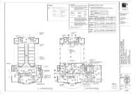
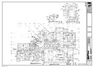
A101-First Floor Plan<br />
A102-Second Floor Plan<br />
A103-First Floor Plan (Partial)<br />
A104-First Floor Plan (Partial)<br />
A105-First Floor Plan (Partial)<br />
A106-First Floor Plan (Partial)<br />
A107-Second Floor Plan (Partial)<br />
A108-Second Floor Plan (Partial)<br />
A111-Roof Plan<br />
A121-First Floor Reflected Ceiling Plan<br />
A122-Second Floor Reflected Ceiling Plan<br />
A130-Finish Plans<br />
A201-North & East Elevation<br />
A202-South & West Elevation<br />
A301-Building Section<br />
A302-Building Section<br />
A303-Building Section<br />
A304-Building Section<br />
EASTERN DISTRICT POLICE STATION 00850 - 1 DRAWING LIST<br />
28103.01 January 15, 2013
A501-Wall Sections<br />
A502-Wall Sections<br />
A503-Wall Sections<br />
A504-Wall Sections<br />
A505-Wall Sections<br />
A506-Wall Sections<br />
A507-Wall Sections<br />
A520-Enlarged Details<br />
A521-Enlarged Details<br />
A522-Enlarged Details<br />
A523-Enlarged Details<br />
A550-Plan Details<br />
A560-Casework Details<br />
A601-Door Schedules<br />
A602-Storefront Elevations<br />
A603-Finish Schedules<br />
A604-Partition Types<br />
A701-Interior Elevations<br />
A702-Interior Elevations<br />
A703-Interior Elevations<br />
A704-Interior Elevations<br />
A705-Interior Elevations<br />
A706-Interior Elevations<br />
S101-Foundation Plan<br />
S102-Second Floor Framing Plan<br />
S103-Roof Framing Plan<br />
S200-Column Schedule<br />
S201-Sections<br />
S202-Sections<br />
S203-Sections<br />
S301-Typical Details<br />
S302-Typical Details<br />
S401-General Notes<br />
M0.1-Mechanical Cover Sheet<br />
M1.1-First Floor Plan – Mechanical<br />
M1.2-Second Floor Plan – Mechanical<br />
M1.3-First Floor Plan – Mechanical Piping<br />
M1.4-Second Floor Plan – Mechanical Piping<br />
M1.5-Roof Plan – Mechanical<br />
M2.1-Part Plan – Mechanical<br />
M3.1-Heating System Piping Schematic<br />
M4.1-Mechanical Details<br />
M4.2-Mechanical Details<br />
M4.3-Mechanical Details<br />
M5.1-Mechanical Schedules<br />
M5.2-Mechanical Schedules<br />
P0.1-Plumbing Cover Sheet<br />
P1.1-Sub Slab Plan – Sanitary<br />
P1.2-First Floor Plan – Sanitary<br />
P1.3-Second Floor Plan – Sanitary<br />
P1.4-First Floor Plan – Domestic Water<br />
P1.5-Second Floor Plan – Domestic Water<br />
P1.6-Roof Plan – Domestic Water<br />
P2.1-Part Plan – Plumbing<br />
P3.1-Domestic Water and Sanitary Riser<br />
P4.1-Plumbing Details<br />
P4.2-Plumbing Details<br />
EASTERN DISTRICT POLICE STATION 00850 - 2 DRAWING LIST<br />
28103.01 January 15, 2013
E0.1-Electrical Cover Sheet<br />
E1.1-Site Plan - Electrical<br />
E2.1-First Floor Plan - Lighting<br />
E2.2-Second Floor Plan - Lighting<br />
E3.1-First Floor Plan - Power<br />
E3.2-Second Floor Plan - Power<br />
E3.3-Roof Plan - Electrical<br />
E4.1-Parts Plan - Electrical<br />
E5.1-Power Riser<br />
E6.1-Details - Fire Alarm<br />
E6.2-Details - Electrical<br />
E6.3-Details - Electrical<br />
E6.4-Details - Electrical<br />
E7.1-Schedules – Electrical<br />
E7.2-Schedules – Panels<br />
E7.3-Schedules – Panels<br />
E7.4-Schedules – Panels<br />
EASTERN DISTRICT POLICE STATION 00850 - 3 DRAWING LIST<br />
28103.01 January 15, 2013
This page intentionally left blank.
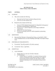
SECTION 15055 - COMMON MOTOR REQUIREMENTS<br />
PART 1<br />
GENERAL<br />
1.1 RELATED DOCUMENTS<br />
A. Drawings and general provisions of Contract, including General and Supplementary<br />
Conditions and Division 01 Specification Sections, apply to this Section, and all sections<br />
of Division 15.<br />
1.2 SUMMARY<br />
A. This Section covers motor requirements for all plumbing and HVAC equipment.<br />
B. This Section includes basic requirements for motors. It includes motors that are factoryinstalled<br />
as part of equipment and appliances as well as field-installed motors.<br />
C. Related Sections: The following Sections contain requirements that relate to this Section:<br />
1.3 REFERENCES<br />
1. Section “Common Work Results for Plumbing.”<br />
2. Section “Common Work Results for HVAC.”<br />
3. Section “Identification for Plumbing Piping and Equipment.”<br />
4. Section “Identification for HVAC piping and Equipment.”<br />
5. Section “Plumbing Equipment.”<br />
6. Section “Heating Ventilating and Air Conditioning”<br />
A. American Bearing Manufacturers Association:<br />
1. ABMA 9 - Load Ratings and Fatigue Life for Ball Bearings, 1990 (R2000).<br />
B. National Electrical Manufacturers Association:<br />
1. NEMA MG 1 - Motors and Generators, 2006.<br />
C. International Electrical Testing Association:<br />
1.4 SUBMITTALS<br />
1. NETA ATS – Acceptance Testing, 2007.<br />
A. Product Data: Submit catalog data for each motor furnished loose. Indicate nameplate<br />
data, standard compliance, electrical ratings and characteristics, and physical<br />
dimensions, weights, mechanical performance data, and support points.<br />
B. Test Reports: Indicate procedures and results for specified factory and field testing and<br />
inspection.<br />
1.5 QUALIFICATIONS<br />
A. Manufacturer: Company specializing in manufacturing products specified in this section<br />
with minimum five years experience.<br />
B. Testing Agency: Company who is a member of the International Electrical Testing<br />
Association and specializing in testing products specified in this section with minimum five<br />
EASTERN DISTRICT POLICE STATION 15055 - 1 COMMON MOTOR REQUIREMENTS<br />
28103.01 January 15, 2013
years experience.<br />
1.6 DELIVERY, STORAGE, AND HANDLING<br />
A. Lift only with lugs provided. Handle carefully to avoid damage to components, enclosure,<br />
and finish.<br />
B. Protect products from weather and moisture by covering with plastic or canvas and by<br />
maintaining heating within enclosure.<br />
C. For extended outdoor storage, remove motors from equipment and store separately.<br />
PART 2<br />
PRODUCTS<br />
2.1 REQUIREMENTS FOR MOTORS<br />
A. General: Requirements below apply to motors covered by this Section except as<br />
otherwise indicated.<br />
1. Motors Larger than 1/2 HP: 3-phase.<br />
2. Motors 1/2 HP and Smaller: Single-phase.<br />
3. Frequency Rating: 60 Hz.<br />
4. Voltage Rating: Determined by voltage of circuit to which motor is connected for<br />
the following motor voltage ratings (utilization voltages):<br />
a. 120 V Circuit: 115 V - motor rating.<br />
b. 208 V Circuit: 200 V - motor rating.<br />
c. 240 V Circuit: 230 V - motor rating.<br />
d. 480 V Circuit: 460 V - motor rating.<br />
5. Minimum service factor shall be 15% and shall apply at frequency and utilization<br />
voltage at which motor is connected. Provide motors, which will not operate in<br />
service factor range when supply voltage is within 10 percent of motor voltage<br />
rating.<br />
6. Capacity: Sufficient to start and operate connected loads at designated speeds in<br />
indicated environment, and with indicated operating sequence, without exceeding<br />
nameplate ratings. Provide motors rated for continuous duty at 100 percent of<br />
rated capacity.<br />
7. Temperature Rise: Based on 40°C ambient except as otherwise indicated.<br />
8. Enclosure: Open dripproof, unless otherwise specified. Provide screen over<br />
slots, where slots will permit passage of human extremities.<br />
9. Provide adjustable motor slide base for belt driven equipment. <strong>Inc</strong>lude adjusting<br />
bolts and locknuts.<br />
B. Three-phase Motors<br />
1. General: Squirrel-cage induction-type conforming to the following requirements<br />
except as otherwise indicated.<br />
2. National Electrical Manufacturers Association NEMA Design Letter<br />
Designation:”B.”<br />
3. Multi-Speed Motors: Separate winding for each speed.<br />
4. Minimum motor efficiencies shall be as follows:<br />
HP<br />
Percent Efficiency, Minimum<br />
1 and less 84.0<br />
1 ½ 85.5<br />
2 86.5<br />
3 89.5<br />
EASTERN DISTRICT POLICE STATION 15055 - 2 COMMON MOTOR REQUIREMENTS<br />
28103.01 January 15, 2013
5 89.5<br />
7 1/2 91.0<br />
10 91.7<br />
15 92.4<br />
20 93.0<br />
25 93.6<br />
30 94.1<br />
40 94.5<br />
50 94.5<br />
60 95.0<br />
75 and larger 95.4<br />
5. Variable Speed Motors for Use With Solid-State Drives: Energy efficient, squirrelcage<br />
induction, design B units and ratings, characteristics, and features<br />
coordinated with and approved by drive manufacturer. Motors shall be labeled to<br />
indicate that they are provided with inverter duty capability in accordance with the<br />
National Electrical Manufacturers Association NEMA MG-1, Part 31.<br />
6. Bearings: Double-shielded, prelubricated ball bearings suitable for radial and<br />
thrust loading of the application. Provide bearings without plugs for grease<br />
fittings.<br />
7. Rugged Duty Motors: Totally enclosed with 1.25 minimum service factor.<br />
Provide motors with regreasable bearings and equipped with capped relief vents.<br />
Insulate windings with nonhygroscopic material. External finish shall be chemical<br />
resistant paint over corrosion resistant primer. Provide integral condensate<br />
drains.<br />
8. Motors for Reduced Inrush Starting: Coordinate with indicated reduced controller<br />
type and with characteristics of driven equipment load. Provide required wiring<br />
leads in motor terminal box to suit control method.<br />
9. All motors shall be provided with manufacturer’s stamped nameplate, to include<br />
all pertinent and capacity data.<br />
C. Single-phase Motors<br />
1. General: Conform to the following requirements except as otherwise indicated.<br />
2. Energy Efficient Motors: One of the following types as selected to suit the starting<br />
torque and other requirements of the specific motor application.<br />
a. Permanent Split Capacitor.<br />
b. Split-Phase Start, Capacitor-Run.<br />
c. Capacitor-Start, Capacitor-Run.<br />
3. Shaded-Pole Motors: Use only for motors smaller than 1/20 hp.<br />
4. Internal Thermal Overload Protection for Motors: Protection shall automatically<br />
opens the power supply circuit to the motor, or a control circuit arranged for<br />
external connection. Protection operates when winding temperature exceeds a<br />
safe value calibrated to the temperature rating of the motor insulation. Provide<br />
device that automatically resets when motor temperature returns to normal range<br />
except as otherwise indicated.<br />
5. Bearings: Belt connected motors and other motors with high radial forces on<br />
motor shaft shall be ball bearing type. Sealed, prelubricated sleeve bearings may<br />
be used for other single phase motors.<br />
2.2 SOURCE QUALITY CONTROL<br />
A. Test motors in accordance with National Electrical Manufacturers Association NEMA MG<br />
1, including winding resistance, no-load speed and current, locked rotor current, insulation<br />
high-potential test, and mechanical alignment tests.<br />
EASTERN DISTRICT POLICE STATION 15055 - 3 COMMON MOTOR REQUIREMENTS<br />
28103.01 January 15, 2013
2.3 BEARING PROTECTION RING<br />
A. All motors driven by a variable frequency PWM drive shall include a maintenance free,<br />
circumferential, conductive micro fiber shaft grounding ring to discharge shaft currents to<br />
ground.<br />
B. Provide AEGIS SGR Bearing Protection Ring as manufactured by Electro Statis<br />
Technology.<br />
PART 3<br />
EXECUTION<br />
3.1 INSTALLATION<br />
A. General: The following requirements apply to field-installed motors.<br />
1. Install motors in accordance with manufacturer’s published instructions and the<br />
following:<br />
a. Direct Connected Motors: Mount securely in accurate alignment.<br />
Connect to driven equipment with coupler of appropriate type and<br />
material for the given duty. Coupler shall be selected for high and range<br />
of motor application.<br />
b. Belt Drive Motors: Use adjustable motor mounting bases. Align pulleys<br />
and install belts. Use belts identified by the manufacturer and tension<br />
belts in accordance with manufacturer recommendations.<br />
3.2 FIELD QUALITY CONTROL<br />
A. Inspect and test in accordance with the International Electrical Testing Association -<br />
NETA ATS, 2007.<br />
3.3 Install Bearing Protection Ring in accordance with manufacturer’s recommendations.<br />
END OF SECTION<br />
EASTERN DISTRICT POLICE STATION 15055 - 4 COMMON MOTOR REQUIREMENTS<br />
28103.01 January 15, 2013
SECTION 15050 - COMMON WORK RESULTS FOR PLUMBING<br />
PART 1<br />
GENERAL<br />
1.1 RELATED DOCUMENTS<br />
A. Drawings and general provisions of Contract, including General and Supplementary<br />
Conditions and Division 1 Specification Sections, apply to this and the other sections of<br />
Division 15.<br />
B. Motors shall comply with Division 15: Section “Common Motor Requirements.”<br />
C. Variable Frequency Drives shall comply with Division 15: Section “Variable Frequency<br />
Drives.”<br />
1.2 SUMMARY<br />
A. This Section includes general administrative and procedural requirements, as well as the<br />
following basic mechanical materials and methods:<br />
1.3 ACRONYMS<br />
1. Submittals.<br />
2. Coordination drawings.<br />
3. Record documents.<br />
4. Operation and Maintenance manuals.<br />
5. Rough-ins.<br />
6. Mechanical installations.<br />
7. Cutting and patching.<br />
8. Concrete equipment base construction requirements.<br />
9. Equipment nameplate data requirement.<br />
10. Labeling and identifying mechanical systems and equipment is specified in<br />
Section “Identification for Plumbing Piping and Equipment.”<br />
11. Non-shrink grout for equipment installations.<br />
12. Field-fabricated metal and wood equipment supports.<br />
13. Installation requirements common to equipment specification Sections.<br />
14. Touchup painting and finishing.<br />
A. The following list of abbreviations are utilized within the specifications and are provided as<br />
a reference:<br />
ADA - American Disability Act<br />
AGA - American Gas Association<br />
ANSI - American National Standards Institute<br />
ASME - American Society of Mechanical Engineers<br />
ASTM - American Society for Testing and Materials<br />
AWS - American Welding Society<br />
AWWA - American Water Works Association<br />
BOCA - Building Officials and Code Administrators<br />
CS - Commercial Standard<br />
CSA - Canadian Standards Association<br />
IBR - Institute of Boiler and Radiator Manufacturers<br />
IEEE - Institute of Electrical and Electronics Engineers<br />
IMC - International Mechanical Code<br />
IPC - International Plumbing Code<br />
MOSHA - Maryland Occupational Safety and Health Administration<br />
EASTERN DISTRICT POLICE STATION 15050- 1 COMMON WORK RESULTS FOR PLUMBING<br />
28103.01 January 15, 2013
1.4 DEFINITIONS<br />
MSSP - Manufacturers Standards Society of the Valve and Fittings Industry<br />
NEC - National Electrical Code<br />
NEMA - National Electrical Manufacturers Association<br />
NFPA - National Fire Protection Association<br />
OSHA - Occupational Safety and Health Administration<br />
TEMA - Tubular Exchanger Manufacturers Association<br />
UL - Underwriters' Laboratories<br />
A. Products: Items purchased for incorporating into the Work, whether purchased for Project<br />
or taken from previously purchased stock. The term product includes the terms material,<br />
equipment, system, and terms of similar intent.<br />
B. Substitutions: Changes proposed by Contractor in products, materials, equipment, and<br />
methods of construction required by the Contract Documents.<br />
1.5 SYSTEM DESCRIPTION<br />
A. Design Requirements: Contract drawings are generally diagrammatic and do not indicate<br />
all offsets, fittings, transitions, access panels and other specialties required.<br />
1.6 SUBMITTALS<br />
1. Furnish and install all items as may be required to fit the work to the conditions<br />
encountered.<br />
2. Arrange piping, equipment and other work generally as shown on the contract<br />
drawings, providing proper clearances and access.<br />
3. Where departures are proposed because of field conditions or other causes,<br />
prepare and submit detailed shop drawing submittal for approval in accordance<br />
with Submittals specified below.<br />
4. Subject to the provisions of Division 1, Architect may make reasonable changes<br />
in location of equipment piping up to the time of rough-in or fabrication.<br />
A. Comply with Section "Submittal Procedures."<br />
B. Shop Drawings and Product Data:<br />
1. Clearly identify all submittals:<br />
a. Indicate intended application, location, etc.<br />
b. Each submittal shall indicate the associated specification section, and<br />
paragraphs. Do not combine product data and shop drawing submittals<br />
from different spec sections into a single submittal package, even though<br />
they may be the same distributor, vendor or part of a single material<br />
order.<br />
c. Clearly indicate the exact type, model number, size and special features<br />
of the proposed item.<br />
d. <strong>Inc</strong>lude catalog spec sheets to completely describe proposed equipment.<br />
e. Factory order forms only showing the required capacities are not<br />
acceptable.<br />
f. Identify all options furnished to meet specifications.<br />
g. If product is within system supplying fixture intended to dispense potable<br />
water for human consumption, including drinking and cooling, submittals<br />
shall indicate that product is “lead free”, containing not more than a<br />
weighted average of 0.25% lead with respect to the wetted surfaces.<br />
h. Solder and flux for soldered joints in potable water piping shall be “lead<br />
EASTERN DISTRICT POLICE STATION 15050- 2 COMMON WORK RESULTS FOR PLUMBING<br />
28103.01 January 15, 2013
free”, containing not more than 0.2% lead.<br />
i. The Architect shall not select equipment ratings and/or options.<br />
Submittals not properly marked shall be returned without review.<br />
C. Product Substitutions: Comply with requirements of Division 01.<br />
D. Comparable Products Submission:<br />
1. Document each request for a proposed comparable product with supporting data<br />
substantiating compliance of proposed product with Basis-of-Design product.<br />
2. Use the attached “Comparable Product Submittal Form” in addition to the<br />
requirements specified herein.<br />
3. Comparable products will not be reviewed without completion of the attached<br />
form.<br />
E. Closeout Submittals:<br />
1. Record Drawings: Prepare record documents in accordance with the<br />
requirements in Section "Closeout Procedures." In addition to the requirements<br />
specified in Division 1, indicate the following installed conditions:<br />
a. Mains and branches of piping systems, with valves and control devices<br />
located and numbered, concealed unions located, and with items<br />
requiring maintenance located (i.e., traps, strainers, expansion<br />
compensators, tanks, etc.). Valve location diagrams, complete with valve<br />
tag chart. Refer to Section “Identification for Plumbing Piping and<br />
Equipment." Indicate actual inverts and horizontal locations of<br />
underground piping.<br />
b. Equipment locations (exposed and concealed), dimensioned from<br />
prominent building lines.<br />
c. Approved substitutions, Contract Modifications, Responses to<br />
Contractor’s Request for Information, and actual equipment and<br />
materials installed.<br />
d. Record the locations and invert elevations of underground installations.<br />
2. Operation and Maintenance Data: Prepare operation and maintenance data in<br />
accordance with Section "Closeout Procedures." In addition to the requirements<br />
specified in Division 01, include the following information for equipment items:<br />
a. List of systems and equipment requiring service manuals.<br />
b. Description of function, normal operating characteristics and limitations,<br />
performance curves, engineering data and tests, and complete<br />
nomenclature and commercial numbers of replacement parts.<br />
c. Manufacturer's printed operating procedures to include start-up, break-in,<br />
and routine and normal operating instructions; regulation, control,<br />
stopping, shutdown, and emergency instructions; and summer and winter<br />
operating instructions.<br />
d. Maintenance procedures for routine preventative maintenance and<br />
troubleshooting; disassembly, repair, and reassembly; aligning and<br />
adjusting instructions.<br />
e. Servicing instructions and lubrication charts and schedules.<br />
f. Systems and Equipment test reports.<br />
3. Commissioning Report<br />
F. Color Selection: Color of finishes shall be as selected by the Architect. Submit colors of<br />
factory finished equipment for acceptance prior to ordering.<br />
G. Products and Materials:<br />
EASTERN DISTRICT POLICE STATION 15050- 3 COMMON WORK RESULTS FOR PLUMBING<br />
28103.01 January 15, 2013
1. Submit complete descriptive data for all materials as follows:<br />
a. Material specifications.<br />
b. Data sheets.<br />
c. Samples.<br />
d. Capacity ratings.<br />
e. Performance curves.<br />
f. Operating characteristics.<br />
g. Catalog cuts.<br />
h. Dimensional drawings.<br />
i. Wiring diagrams.<br />
j. Installation instruction.<br />
k. Any other information necessary to indicate compliance with contract<br />
documents.<br />
l. Lead Free, for potable water service.<br />
2. Edit submittal data specifically for application to this project.<br />
3. Submit actual operating conditions and characteristics for all equipment.<br />
4. Catalogs or catalog cuts are not acceptable unless the particular item and all<br />
relative data has been marked in such a manner as to be clearly defined.<br />
5. Color of finishes shall be as selected by the Architect. Submit colors of factory<br />
finished equipment for acceptance prior to ordering.<br />
6. No mechanical item shall be fabricated, purchased, delivered to the site or<br />
installed, until reviewed by the Architect.<br />
a. After the proposed materials have been approved, no substitution will be<br />
permitted except where approved by the Architect.<br />
7. Provide the following shop drawing and product data submittals in addition to<br />
submittals required under individual specification sections.<br />
1.7 QUALITY ASSURANCE<br />
Items and Systems:<br />
Drains - Floor, Roof, Etc.<br />
Pipes, Valves, Fittings and Accessories<br />
Thermometers and Gauges<br />
Thermal Insulation Materials<br />
Back Flow Preventors<br />
Expansion Compensators<br />
Expansion Tanks<br />
Flexible Connections<br />
Cleanouts<br />
Pressure Relief Valves<br />
Pipes, Guides, Sleeves, Anchors and Supports<br />
Piping Equipment Supports<br />
Pipe Leakage Reports<br />
Plumbing Fixtures<br />
Balancing Reports<br />
Brazing and Soldering Procedures<br />
Lubricants and Instructions Record and Information Booklet<br />
Piping Cleaning Materials<br />
Gas fired Water Heaters<br />
Sump Pump<br />
Recirculation Pumps<br />
Any other equipment requested by the Architect.<br />
A. Underwriter’s Laboratory (UL) Requirements: All equipment containing electrical<br />
components and provided under Division 15 shall bear the Underwriter’s Laboratory (UL)<br />
EASTERN DISTRICT POLICE STATION 15050- 4 COMMON WORK RESULTS FOR PLUMBING<br />
28103.01 January 15, 2013
label, as a complete packaged system.<br />
1. Equipment not provided with a UL label shall be tested in the field, certified and<br />
provided with a listed label at the installer’s expense.<br />
a. Field testing shall be performed by a testing agency approved by the<br />
authority having jurisdiction.<br />
b. Provide services of a UL recognized, independent Electrical Testing<br />
Laboratory (ETL) to provide field inspection and testing. Provide and ETL<br />
Label on all such equipment.<br />
B. Fire Safe Materials: Unless otherwise indicated, materials shall conform to UL, National<br />
Fire Protection Agency (NFPA) or American Society for Testing and Materials (ASTM)<br />
standards for fire safety with smoke and fire hazard rating not exceeding flame spread of<br />
25 and smoke developed of 50.<br />
1.8 DELIVERY, STORAGE, AND HANDLING<br />
A. Comply with Section “Product Requirements”:<br />
1.9 SEQUENCING<br />
A. Coordinate mechanical equipment installation with other building components.<br />
B. Arrange for chases, slots, and openings in building structure during progress of<br />
construction to allow for mechanical installations.<br />
C. Coordinate the installation of required supporting devices and set sleeves in<br />
poured-in-place concrete and other structural components as they are constructed.<br />
D. Sequence, coordinate, and integrate installations of mechanical materials and equipment<br />
for efficient flow of the Work. Coordinate installation of large equipment requiring<br />
positioning prior to closing in the building.<br />
E. Coordinate connection of electrical services.<br />
F. Coordinate connection of mechanical systems with exterior underground and overhead<br />
utilities and services. Comply with requirements of governing regulations, franchised<br />
service companies, and controlling agencies.<br />
G. Coordinate requirements for access panels and doors where mechanical items requiring<br />
access are concealed behind finished surfaces.<br />
H. Coordinate installation of identifying devices after completing covering and painting where<br />
devices are applied to surfaces. Install identifying devices prior to installing acoustical<br />
ceilings and similar concealment.<br />
1.10 DISCREPANCIES<br />
A. Where discrepancies occur between the drawings and specifications or within either<br />
document itself, the item or arrangement of better quality, greater quantity or higher cost<br />
shall be included in the contract price. The Architect shall decide on the item and manner<br />
in which the work shall be provided, based on the design intent of the documents.<br />
1.11 ELECTRONIC CAD DOCUMENTS<br />
A. Requests for electronic CAD documents will be accommodated to the contractors and<br />
EASTERN DISTRICT POLICE STATION 15050- 5 COMMON WORK RESULTS FOR PLUMBING<br />
28103.01 January 15, 2013
installers upon their completion of Kibart’s Electronic Document Release of Liability Form<br />
and payment for time and expense for document preparation.<br />
1. Kibart’s document preparation fee is as follows:<br />
a. Two hundred and fifty dollars ($250.00) for the first five (5) drawings.<br />
b. Fifty dollars ($50.00) for each drawing thereafter.<br />
PART 2<br />
PRODUCTS<br />
2.1 PRODUCT SELECTION<br />
A. General Product Requirements: Provide products that comply with Contract Documents<br />
that are undamaged and new at time of installation.<br />
1. Provide products complete with accessories, trim, finish, safety guards, and other<br />
devices and details needed for complete installation and intended use and effect.<br />
2. Standard Products: Where available, provide standard products of types that<br />
have been produced and used successfully in similar situations on other projects.<br />
3. Where products are accompanied by the term as selected, Architect will make<br />
selection.<br />
4. Where products are accompanied by the term match sample, sample to be<br />
matched is Architect's.<br />
5. Descriptive, performance, and reference standard requirements in the<br />
Specifications establish salient characteristics of products.<br />
B. General Compliance Requirements: Compliance requirements for individual products, as<br />
indicated in Contract Documents, are multiple in nature and may include generic<br />
descriptions, performance requirements, compliance with reference standards,<br />
conformance with graphic details and other similar forms and methods of indicating<br />
requirements, all of which must be complied with.<br />
C. Procedures for Selecting Products: Contractor's options for selecting products are limited<br />
by Contract Document requirements, and are not controlled by industry traditions or<br />
procedures experienced by Contractor on previous construction projects.<br />
D. Products specified by Reference Standards, Codes and Regulations: Select from among<br />
products, which can be shown to comply with referenced documents.<br />
E. Products specified by Naming Products and Manufacturers: Select from among products<br />
listed.<br />
F. Products specified by Naming One Manufacturer's Product as the Basis-of-Design with<br />
Reference to Other Manufacturers: Select either the specified Basis-of-Design product or<br />
an approved comparable product by one of the other named manufacturers.<br />
1. Comply with provisions in Comparable Products Article to obtain approval for use<br />
of a comparable product by one of the named manufacturers.<br />
G. Products specified by Naming One Manufacturer's Product and Indicating Option of<br />
Selecting Comparable Products by stating or Approved Equivalent or similar language:<br />
Select either the specified product or an approved comparable product.<br />
1. Comply with provisions in Comparable Products Article to obtain approval for use<br />
of a comparable product by one of the named or un-named manufacturers.<br />
EASTERN DISTRICT POLICE STATION 15050- 6 COMMON WORK RESULTS FOR PLUMBING<br />
28103.01 January 15, 2013
H. Visual Matching Specification: Where Specifications require matching an established<br />
Sample, select a product that complies with requirements and, matches Architect's<br />
sample. Architect's decision will be final on whether proposed product matches<br />
satisfactorily.<br />
I. Visual Selection Specification: Where Specifications include the phrase as selected from<br />
manufacturer's standard colors, patterns, textures or similar phrase, select a product that<br />
complies with other specified requirements. Architect will select color, pattern, and<br />
texture.<br />
1. Standard Range: Where Specifications include the phrase standard range of<br />
colors, patterns, textures or similar phrase, Architect will select color, pattern, or<br />
texture from manufacturer's product line that does not include premium items.<br />
2. Full Range: Where Specifications include the phrase full range of colors,<br />
patterns, textures or similar phrase, Architect will select color, pattern, or texture<br />
from manufacturer's product line that includes both standard and premium items.<br />
2.2 COMPARABLE PRODUCTS<br />
A. Where Basis-of-Design products are specified by name, submit the following, in addition<br />
to other required submittals, to obtain approval of a comparable product by one of the<br />
named manufacturers:<br />
1. Evidence that the proposed product does not require extensive revisions to the<br />
Contract Documents that it is consistent with the Contract Documents and will<br />
produce the indicated results, and that it is compatible with other portions of the<br />
Work. Use the attached Comparable Products Submittal Form in addition to<br />
requirements listed herein.<br />
2. Detailed comparison of significant qualities of proposed product with the Basis-of-<br />
Design product in the Specifications. Significant qualities include attributes such<br />
as performance, weight, size, durability, serviceability, visual effect, and specific<br />
features and requirements indicated.<br />
3. Evidence that proposed product provides specified warranty.<br />
4. List of similar installations for completed projects with project names and<br />
addresses and names and addresses of architects and owners, if requested.<br />
5. Samples, if requested.<br />
PART 3<br />
EXECUTION<br />
3.1 PREPARATION<br />
A. Interface With Site Utility Companies:<br />
1. Contact MISS UTILITY prior to any excavation or underground work.<br />
2. Contact local utility companies (gas, water, sewer, etc.) immediately upon award<br />
of contract. Do not install related equipment until fully coordinated with<br />
appropriate utilities.<br />
3. Provide all construction schedules, dates of requested services, outage windows,<br />
equipment locations, etc. necessary for utility work.<br />
4. Gas Utility:<br />
a. Coordinate service entrance equipment and related layout with gas<br />
company prior to ordering or installing any equipment or systems.<br />
b. Furnish and install all incoming concrete pads, sleeves, connections, etc.<br />
5. Water and Sewer Utilities:<br />
a. Coordinate flow, usage and pressure requirements with local water and<br />
sewer authorities as necessary to obtain services.<br />
EASTERN DISTRICT POLICE STATION 15050- 7 COMMON WORK RESULTS FOR PLUMBING<br />
28103.01 January 15, 2013
3.2 INSTALLATION<br />
A. General: Sequence, coordinate, and integrate the various elements of mechanical<br />
systems, materials, and equipment. Comply with the following requirements:<br />
1. Coordinate mechanical systems, equipment, and materials installation with other<br />
building components.<br />
2. Verify all dimensions by field measurements.<br />
3. Arrange for chases, slots, and openings in other building components during<br />
progress of construction, to allow for mechanical installations.<br />
4. Coordinate the installation of required supporting devices and sleeves to be set in<br />
poured-in-place concrete and other structural components, as they are<br />
constructed.<br />
5. Sequence, coordinate, and integrate installations of mechanical materials and<br />
equipment for efficient flow of the Work. Give particular attention to large<br />
equipment requiring positioning prior to closing in the building.<br />
6. Where systems, materials and equipment are intended for overhead installation,<br />
and where mounting heights are not detailed or dimensioned, install systems,<br />
materials, and equipment to provide the maximum headroom possible.<br />
7. Coordinate connection of mechanical systems with exterior underground and<br />
overhead utilities and services. Comply with requirements of governing<br />
regulations, franchised service companies, and controlling agencies. Provide<br />
required connection for each service.<br />
8. Install systems, materials, and equipment to conform with approved submittal<br />
data, including coordination drawings, to greatest extent possible. Conform to<br />
arrangements indicated by the Contract Documents, recognizing that portions of<br />
the Work are shown only in diagrammatic form. Where coordination<br />
requirements conflict with individual system requirements, refer conflict to the<br />
Architect.<br />
9. Install systems, materials, and equipment level and plumb, parallel and<br />
perpendicular to other building systems and components.<br />
10. Install mechanical equipment to facilitate servicing, maintenance, and repair or<br />
replacement of equipment components. As much as practical, connect<br />
equipment for ease of disconnecting, with minimum of interference with other<br />
installations. Extend grease fittings to an accessible location.<br />
11. Install access panel or doors where units are concealed behind finished surfaces.<br />
Access panels and doors are specified in Section "Access Doors” and within this<br />
section.<br />
12. Install systems, materials, and equipment giving right-of-way priority to systems<br />
required to be installed at a specified slope.<br />
B. Rough-In<br />
1. Verify final locations for rough-ins with field measurements and with the<br />
requirements of the actual equipment to be connected.<br />
2. Refer to equipment specifications in Divisions 2 through 16 for rough-in<br />
requirements.<br />
C. Housekeeping and Equipment Pads<br />
1. Construct pads of dimensions indicated, but not less than 4 inches (100 mm)<br />
larger than supported unit in both directions. Follow supported equipment<br />
manufacturer's setting templates for anchor bolt and tie locations. Use 3000-psi<br />
(20.70MPa), 28-day compressive strength concrete and reinforcement bars as<br />
specified in Section "Cast-in-Place Concrete."<br />
EASTERN DISTRICT POLICE STATION 15050- 8 COMMON WORK RESULTS FOR PLUMBING<br />
28103.01 January 15, 2013
D. Erection of Metal Supports and Anchorage<br />
1. Cut, fit, and place miscellaneous metal supports accurately in location, alignment,<br />
and elevation to support and anchor mechanical materials and equipment.<br />
2. Field Welding: Comply with AWS D1.1, "Structural Welding Code -Steel”, 2001.<br />
E. Erection of Wood Supports and Anchorage<br />
1. Cut, fit, and place wood grounds, nailers, blocking, and anchorage to support and<br />
anchor mechanical materials and equipment.<br />
2. Select fastener sizes that will not penetrate members where opposite side will be<br />
exposed to view or will receive finish materials. Make tight connections between<br />
members. Install fasteners without splitting wood members.<br />
3. Attach to substrates as required to support applied loads.<br />
F. Grouting<br />
G. Lintels<br />
H. Boilers<br />
1. Install nonmetallic non-shrink grout for mechanical equipment base bearing<br />
surfaces, pump and other equipment base plates, and anchors. Mix grout<br />
according to manufacturer's printed instructions.<br />
2. Clean surfaces that will come into contact with grout.<br />
3. Provide forms for placement of grout, as required.<br />
4. Avoid air entrapment when placing grout.<br />
5. Place grout to completely fill equipment bases.<br />
6. Place grout on concrete bases to provide a smooth bearing surface for<br />
equipment.<br />
7. Place grout around anchors.<br />
8. Cure placed grout according to manufacturer's printed instructions.<br />
1. Lintels shall be provided for openings in masonry, brick, concrete, etc. walls to<br />
accommodate work of this division.<br />
a. Lintels shall be provided under this division when not being provided<br />
under other divisions. Lintels shall be approved by the Architect.<br />
1. Installation of boilers, water heater, and all other pressure vessels shall be made<br />
in compliance with the State of Maryland Pressure Vessel and Safety Act and<br />
CSD-1.<br />
3.3 CUTTING AND PATCHING<br />
A. General: Perform cutting and patching in accordance with Section "Execution<br />
Requirements." In addition to the requirements specified in Division 1, the following<br />
requirements apply:<br />
1. Protection of Installed Work: During cutting and patching operations, protect<br />
adjacent installations.<br />
B. Perform cutting, fitting, and patching of mechanical equipment and materials required to:<br />
1. Uncover Work to provide for installation of ill-timed Work.<br />
2. Remove and replace defective Work.<br />
EASTERN DISTRICT POLICE STATION 15050- 9 COMMON WORK RESULTS FOR PLUMBING<br />
28103.01 January 15, 2013
3. Remove and replace Work not conforming to requirements of the Contract<br />
Documents.<br />
4. Remove samples of installed Work as specified for testing.<br />
5. Install equipment and materials in existing structures.<br />
6. Upon written instructions from the Architect, uncover and restore Work to provide<br />
for Architect observation of concealed Work.<br />
C. Cut, remove and legally dispose of selected mechanical equipment, components, and<br />
materials as indicated, including but not limited to removal of mechanical piping, heating<br />
units, plumbing fixtures and trim, and other mechanical items made obsolete by the new<br />
Work.<br />
D. Protect the structure, furnishings, finishes, and adjacent materials not indicated or<br />
scheduled to be removed.<br />
E. Provide and maintain temporary partitions or dust barriers adequate to prevent the spread<br />
of dust and dirt to adjacent areas.<br />
F. Patch finished surfaces and building components using new materials specified for the<br />
original installation and using experienced Installers. Installers' qualifications refer to the<br />
materials and methods required for the surface and building components being patched.<br />
3.4 PAINTING AND FINISHING<br />
A. Refer to Section "Interior Painting” for field painting requirements.<br />
B. Damage and Touch Up: Repair marred and damaged factory-painted finishes with<br />
materials and procedures to match original factory finish.<br />
C. Do not paint manufacturer's labels or tags.<br />
3.5 PENETRATION OF WATERPROOF CONSTRUCTION<br />
A. Coordinate the work to minimize penetration of waterproof construction, including roofs,<br />
exterior walls and interior waterproof construction.<br />
B. Furnish and install drains, curbs, vent assemblies, sleeves, flashing, etc. specifically<br />
designed for application to the particular construction. Install system in accordance with<br />
the roofing manufacturer's instructions.<br />
3.6 EXCAVATION AND BACKFILLING<br />
A. General<br />
3.7 CLEANING<br />
1. Perform all necessary excavation, for installation of work under Division 15, in<br />
accordance with Division 2.<br />
A. Clean surfaces prior to application of insulation, adhesives, coating, and paint.<br />
B. Provide factory applied finish where specified.<br />
C. Protect all finishes, and restore all finishes to their original condition if damaged as a<br />
result of work under Division 15.<br />
EASTERN DISTRICT POLICE STATION 15050- 10 COMMON WORK RESULTS FOR PLUMBING<br />
28103.01 January 15, 2013
D. Remove all construction marking and writing from exposed equipment, piping and<br />
building surfaces.<br />
E. General: General cleaning during construction is required by the General Conditions and<br />
included in Section Temporary Facilities.<br />
F. Cleaning: Employ experienced workers or professional cleaners for final cleaning. Clean<br />
each surface or unit to the condition expected in a normal, commercial building cleaning<br />
and maintenance program. Comply with manufacturer's instructions.<br />
G. Remove all mechanical clipping, wiring, nuts, bolts, etc. left on top of ceilings and ceiling<br />
tiles.<br />
3.8 PROTECTION<br />
A. Protect work, material and equipment from weather and construction operations before<br />
and after installation.<br />
B. Properly store and handle all materials and equipment.<br />
C. Cover temporary openings in piping and equipment to prevent the entrance of water, dirt,<br />
debris, and other foreign matter.<br />
3.9 LUBRICATION<br />
A. All bearings, motors and all equipment requiring lubrication shall be provided with<br />
accessible fittings.<br />
B. Before turning over the equipment to the Owner, provide the following:<br />
1. Fully lubricate each item of equipment.<br />
2. Provide 1 year's supply of lubricant for each type of lubricant.<br />
3. Provide complete written lubricating instructions, together with diagram locating<br />
the points requiring lubrication.<br />
C. Motors and equipment shall be provided with grease lubricated roller or ball bearings with<br />
Alemite or equal extended grease fittings and drain plugs.<br />
3.10 ELECTRICAL WORK<br />
A. It is the intent to provide a complete and operational system. The work between Division<br />
15 and 16 is complementary and is meant to produce a single and operating system.<br />
Contractor shall make its own determination as to the distribution of responsibility among<br />
the various trades.<br />
B. All electrical work performed under Division 15 shall be provided in accordance with<br />
Division 16.<br />
3.11 PROVISIONS FOR ACCESS<br />
A. Furnish and install adequate access to all plumbing components. The following list shall<br />
be used as a guide only:<br />
1. Plumbing equipment.<br />
2. Valves.<br />
EASTERN DISTRICT POLICE STATION 15050- 11 COMMON WORK RESULTS FOR PLUMBING<br />
28103.01 January 15, 2013
3. Cleanouts.<br />
4. Traps.<br />
B. Access shall be adequate as determined by the Architect.<br />
C. Refer to contract drawings where panels have been specifically located.<br />
D. Provide additional panels for adequate access as indicated in paragraph A above.<br />
E. Where access is by means of liftout ceiling tiles or panels mark each panel using small<br />
color-coded or numbered tabs. Provide an index chart for identification. Place markers in<br />
corner of tile.<br />
3.12 OPERATION OF EQUIPMENT<br />
A. Clean all systems and equipment prior to initial operation for testing and balancing.<br />
B. Do not operate equipment unless all proper safety devices or controls are operational.<br />
C. Provide all maintenance and service for equipment, which is operated during construction.<br />
D. Where specified and otherwise required, provide the services of a manufacturer's factory<br />
trained service organization to start the equipment.<br />
E. Do not use mechanical systems for temporary services during construction unless<br />
authorized in writing by the Architect.<br />
1. Where such authorization is granted, temporary use of equipment shall not limit<br />
or otherwise affect warranties or guarantees of the work.<br />
F. Upon completion of work, clean and restore all equipment to new conditions and replace<br />
all filters.<br />
3.13 DEMONSTRATION<br />
A. Demonstrate operation and maintenance of equipment and systems to Owner’s<br />
personnel a minimum two (2) weeks prior to date of final inspection.<br />
1. For equipment requiring seasonal operation, perform instructions for other<br />
seasons at the same time.<br />
2. Training period shall be performed within 1 - two week period.<br />
B. Use operation and maintenance manuals and video as basis of instruction. Review<br />
contents of manual and video with personnel in detail to explain all aspects of operation<br />
and maintenance.<br />
C. Demonstrate the following:<br />
1. Start up.<br />
2. Operation.<br />
3. Control.<br />
4. Adjustment.<br />
5. Trouble shooting.<br />
6. Servicing.<br />
7. Maintenance.<br />
8. Shutdown.<br />
EASTERN DISTRICT POLICE STATION 15050- 12 COMMON WORK RESULTS FOR PLUMBING<br />
28103.01 January 15, 2013
D. Provide at least 8 hours straight time instruction to the operating personnel.<br />
1. This instruction period shall consist of not less than five-8 hour days.<br />
2. Time of instruction shall be designated by the Owner.<br />
3. This instruction shall be in addition to instructional requirements of specific<br />
equipment specified elsewhere in Division 15.<br />
3.14 WALL AND FLOOR PENETRATION<br />
A. All penetrations of partitions, walls and floors by piping or conduit under Division 15 shall<br />
be sealed and caulked. Provide U.L. listed fire stopping systems at penetrations through<br />
fire rated walls.<br />
3.15 EQUIPMENT PROVIDED UNDER ANOTHER DIVISION AND BY OTHERS<br />
A. Make all system connections required to equipment furnished and installed under another<br />
division and by others.<br />
B. It shall be the responsibility of the Contractor to coordinate all necessary data from the<br />
equipment supplied under other Divisions.<br />
EASTERN DISTRICT POLICE STATION 15050- 13 COMMON WORK RESULTS FOR PLUMBING<br />
28103.01 January 15, 2013
COMPARABLE PRODUCT SUBMITTAL FORM<br />
Table of Compliance (Sample)<br />
Shop Drawing and Product Data Submittal<br />
The Contractor shall prepare a Table of Compliance Form similar in format to the sample shown below to<br />
facilitate and expedite the Shop Drawing and Product Data Review. Failure to comply with this<br />
requirement will be basis for rejecting the Submittal.<br />
The Table of Compliance Form will list and compare the performance parameters as the submitted<br />
equipment to that listed on equipment schedule and specifications as basis of design. All non-compliance<br />
items (differences) must be explained in full, indicating their impact, if any, on maintainability, durability,<br />
energy use, operating costs, code compliance and environmental considerations.<br />
(Sample)<br />
TABLE OF COMPLIANCE<br />
EQUIPMENT: _______________________<br />
SPEC. SECTION: _______________________<br />
BASIS OF DESIGN<br />
SAMPLE ITEMS<br />
Flow (Cfm Or Gpm)<br />
Ext. Static Press.<br />
Head (Ft.)<br />
Electrical Requirements<br />
Cooling Capacity<br />
Heating Capacity<br />
Discharge Air Temp.<br />
Filter Type & Eff.<br />
Equipment Eff. (Eer)<br />
Sound Data<br />
Weights<br />
Etc.<br />
DRAWINGS SUBMITTED EXPLANATION<br />
Specifications:<br />
A. Quality assurance<br />
compliance (ARI)<br />
(ASHRAE)<br />
(AMCA)<br />
(UL)<br />
B. Specifications: List each<br />
and every specification<br />
paragraph<br />
C. Etc.<br />
Other:<br />
END OF SECTION<br />
EASTERN DISTRICT POLICE STATION 15050- 14 COMMON WORK RESULTS FOR PLUMBING<br />
28103.01 January 15, 2013
SECTION 15051 - COMMON WORK RESULTS FOR HVAC<br />
PART 1<br />
GENERAL<br />
1.1 RELATED DOCUMENTS<br />
A. Drawings and general provisions of Contract, including General and Supplementary<br />
Conditions and Division 01 Specification Sections, apply to this and the other sections of<br />
Division 15.<br />
1.2 SUMMARY<br />
A. This Section includes general administrative and procedural requirements, as well as the<br />
following basic mechanical materials and methods:<br />
1.3 ACRONYMS<br />
1. Submittals.<br />
2. Coordination drawings.<br />
3. Record documents.<br />
4. Operation and Maintenance manuals.<br />
5. Rough-ins.<br />
6. Mechanical installations.<br />
7. Cutting and patching.<br />
8. Concrete equipment base construction requirements.<br />
9. Equipment nameplate data requirement.<br />
10. Labeling and identifying mechanical systems and equipment is specified in<br />
Section “Identification for HVAC Piping and Equipment.”<br />
11. Non-shrink grout for equipment installations.<br />
12. Field-fabricated metal and wood equipment supports.<br />
13. Installation requirements common to equipment specification Sections.<br />
14. Touchup painting and finishing.<br />
A. The following list of abbreviations are utilized within the specifications and are provided as<br />
a reference:<br />
AABC - Associated Air Balance Council<br />
ADA - American Disability Act<br />
ADC - Air Diffusion Council<br />
AGA - American Gas Association<br />
AMCA - Air Moving and Conditioning Association<br />
ANSI - American National Standards Institute<br />
ARI - Air Conditioning and Refrigeration Institute<br />
ASHRAE - American Society of Heating, Refrigerating and Air<br />
Conditioning Engineers<br />
ASME - American Society of Mechanical Engineers<br />
ASTM - American Society for Testing and Materials<br />
AWS - American Welding Society<br />
AWWA - American Water Works Association<br />
BOCA - Building Officials and Code Administrators<br />
CS - Commercial Standard<br />
CSA - Canadian Standards Association<br />
IBR - Institute of Boiler and Radiator Manufacturers<br />
IEEE - Institute of Electrical and Electronics Engineers<br />
IMC - International Mechanical Code<br />
IPC - International Plumbing Code<br />
EASTERN DISTRICT POLICE STATION 15051 - 1 COMMON WORK RESULTS FOR HVAC<br />
28103.01 January 15, 2013
MOSHA - Maryland Occupational Safety and Health Administration<br />
MSSP - Manufacturers Standards Society of the Valve and Fittings<br />
Industry<br />
NEC - National Electrical Code<br />
NEMA - National Electrical Manufacturers Association<br />
NFPA - National Fire Protection Association<br />
OSHA - Occupational Safety and Health Administration<br />
SMACNA - Sheet Metal and Air Conditioning Contractors National<br />
Association<br />
TEMA - Tubular Exchanger Manufacturers Association<br />
UL - Underwriters' Laboratories<br />
1.4 DEFINITIONS<br />
A. Products: Items purchased for incorporating into the Work, whether purchased for Project<br />
or taken from previously purchased stock. The term product includes the terms material,<br />
equipment, system, and terms of similar intent.<br />
B. Substitutions: Changes proposed by Contractor in products, materials, equipment, and<br />
methods of construction required by the Contract Documents.<br />
1.5 SUBMITTALS<br />
A. Comply with Section "Submittal Procedures."<br />
B. Shop Drawings and Product Data:<br />
1. Clearly identify all submittals:<br />
a. Indicate intended application, location, etc.<br />
b. Each submittal shall indicate the associated specification section, and<br />
paragraphs. Do not combine product data and shop drawing submittals<br />
from different spec sections into a single submittal package, even though<br />
they may be the same distributor, vendor or part of a single material<br />
order.<br />
c. Clearly indicate the exact type, model number, size and special features<br />
of the proposed item.<br />
d. <strong>Inc</strong>lude catalog spec sheets to completely describe proposed equipment.<br />
e. Factory order forms only showing the required capacities are not<br />
acceptable.<br />
f. Identify all options furnished to meet specifications.<br />
g. The Architect shall not select equipment ratings and/or options.<br />
Submittals not properly marked shall be returned without review.<br />
C. Product Substitutions: Comply with requirements of Division 01.<br />
D. Comparable Products Submission:<br />
1. Document each request for a proposed comparable product with supporting data<br />
substantiating compliance of proposed product with Basis-of-Design product.<br />
2. Use the attached “Comparable Product Submittal Form” in addition to the<br />
requirements specified herein.<br />
3. Comparable products will not be reviewed without completion of the attached<br />
form.<br />
E. Closeout Submittals:<br />
EASTERN DISTRICT POLICE STATION 15051 - 2 COMMON WORK RESULTS FOR HVAC<br />
28103.01 January 15, 2013
1. Record Drawings: Prepare record documents in accordance with the<br />
requirements in Division 1 Section "Closeout Procedures." In addition to the<br />
requirements specified in Division 1, indicate the following installed conditions:<br />
a. Ductwork mains and branches, size and location, for both exterior and<br />
interior; locations of dampers and other control devices; filters, boxes,<br />
and terminal units requiring periodic maintenance or repair.<br />
b. Mains and branches of piping systems, with valves and control devices<br />
located and numbered, concealed unions located, and with items<br />
requiring maintenance located (i.e., traps, strainers, expansion<br />
compensators, tanks, etc.). Valve location diagrams, complete with valve<br />
tag chart. Refer to Section “Identification for HVAC Piping and<br />
Equipment." Indicate actual inverts and horizontal locations of<br />
underground piping.<br />
c. Equipment locations (exposed and concealed), dimensioned from<br />
prominent building lines.<br />
d. Approved substitutions, Contract Modifications, Responses to<br />
Contractor’s Request for Information, and actual equipment and<br />
materials installed.<br />
e. Record the locations and invert elevations of underground installations.<br />
2. Operation and Maintenance Data: Prepare operation and maintenance data in<br />
accordance with Section "Closeout Procedures." In addition to the requirements<br />
specified in Division 01, include the following information for equipment items:<br />
a. List of systems and equipment requiring service manuals.<br />
b. Description of function, normal operating characteristics and limitations,<br />
performance curves, engineering data and tests, and complete<br />
nomenclature and commercial numbers of replacement parts.<br />
c. Manufacturer's printed operating procedures to include start-up, break-in,<br />
and routine and normal operating instructions; regulation, control,<br />
stopping, shutdown, and emergency instructions; and summer and winter<br />
operating instructions.<br />
d. Maintenance procedures for routine preventative maintenance and<br />
troubleshooting; disassembly, repair, and reassembly; aligning and<br />
adjusting instructions.<br />
e. Servicing instructions and lubrication charts and schedules.<br />
f. Systems and Equipment test reports.<br />
3. Commissioning Report.<br />
F. Color Selection: Color of finishes shall be as selected by the Architect. Submit colors of<br />
factory finished equipment for acceptance prior to ordering.<br />
G. Products and Materials:<br />
1. Submit complete descriptive data for all materials as follows:<br />
a. Material specifications.<br />
b. Data sheets.<br />
c. Samples.<br />
d. Capacity ratings.<br />
e. Performance curves.<br />
f. Operating characteristics.<br />
g. Catalog cuts.<br />
h. Dimensional drawings.<br />
i. Wiring diagrams.<br />
j. Installation instruction.<br />
k. Any other information necessary to indicate compliance with contract<br />
documents.<br />
2. Edit submittal data specifically for application to this project.<br />
EASTERN DISTRICT POLICE STATION 15051 - 3 COMMON WORK RESULTS FOR HVAC<br />
28103.01 January 15, 2013
3. Submit actual operating conditions and characteristics for all equipment.<br />
4. Catalogs or catalog cuts are not acceptable unless the particular item and all<br />
relative data has been marked in such a manner as to be clearly defined.<br />
5. Color of finishes shall be as selected by the Architect. Submit colors of factory<br />
finished equipment for acceptance prior to ordering.<br />
6. No mechanical item shall be fabricated, purchased, delivered to the site or<br />
installed, until reviewed by the Architect.<br />
a. After the proposed materials have been approved, no substitution will be<br />
permitted except where approved by the Architect.<br />
7. Provide the following shop drawing and product data submittals in addition to<br />
submittals required under individual specification sections.<br />
1.6 QUALITY ASSURANCE<br />
Items and Systems<br />
Pipes, Valves, Fittings and Accessories<br />
Thermometers and Gauges<br />
Fans<br />
Automatic Temperature Control System<br />
Thermal Insulation Materials<br />
Pumps<br />
Duct Heating Coils<br />
Expansion Compensators<br />
Flexible Connections<br />
Dampers<br />
Manual Air Vents<br />
Pressure Relief Valves<br />
NIST Calibration Sheets<br />
Pipes, Guides, Sleeves, Anchors and Supports<br />
HVAC Equipment Supports<br />
Grilles, Registers, Diffusers<br />
Baseboard Unit Heaters<br />
Variable Frequency Drives<br />
Sheet Metal Ductwork Layout<br />
Duct Leakage Test Reports<br />
Duct Sealing System<br />
Balancing Reports<br />
Roof Top Units<br />
Welder’s Certificates<br />
Brazing and Soldering Procedures<br />
Lubricants and Instructions Record and Information Booklet<br />
Piping Cleaning Materials<br />
Variable Air <strong>Volume</strong> Boxes<br />
Boilers<br />
Hydronic Unit Heater<br />
Hydronic Cabinet Unit Heaters<br />
Any other equipment requested by the Architect.<br />
A. Underwriter’s Laboratory (UL) Requirements: All equipment containing electrical<br />
components and provided under Division 15 shall bear the Underwriter’s Laboratory (UL)<br />
label, as a complete packaged system.<br />
1. Equipment not provided with a UL label shall be tested in the field, certified and<br />
provided with a listed label at the installer’s expense.<br />
a. Field testing shall be performed by a testing agency approved by the<br />
EASTERN DISTRICT POLICE STATION 15051 - 4 COMMON WORK RESULTS FOR HVAC<br />
28103.01 January 15, 2013
authority having jurisdiction.<br />
b. Provide services of a UL recognized, independent Electrical Testing<br />
Laboratory (ETL) to provide field inspection and testing. Provide and ETL<br />
Label on all such equipment.<br />
B. Fire Safe Materials: Unless otherwise indicated, materials shall conform to UL, National<br />
Fire Protection Agency (NFPA) or American Society for Testing and Materials (ASTM)<br />
standards for fire safety with smoke and fire hazard rating not exceeding flame spread of<br />
25 and smoke developed of 50.<br />
1.7 DELIVERY, STORAGE, AND HANDLING<br />
A. Comply with Section “Product Requirements”:<br />
1.8 SEQUENCING<br />
1. Deliver, store, and handle products according to manufacturer's<br />
recommendations, using means and methods that will prevent damage,<br />
deterioration, and loss, including theft.<br />
2. Schedule delivery to minimize long-term storage at Project Site and to prevent<br />
overcrowding of construction spaces.<br />
3. Coordinate delivery with installation time to assure minimum holding time for<br />
items that are flammable, hazardous, easily damaged, or sensitive to<br />
deterioration, theft, and other losses.<br />
4. Deliver products to Project Site in an undamaged condition in manufacturer's<br />
original sealed container or other packaging system, complete with labels and<br />
instructions for handling, storing, unpacking, protecting, and installing.<br />
5. Inspect products upon delivery to ensure compliance with Contract Documents<br />
and to ensure that products are undamaged and properly protected.<br />
6. Store products in manner that will facilitate inspection and measurement.<br />
7. Store materials in a manner that will not endanger project structure.<br />
8. Store products subject to damage by elements above ground, under cover in a<br />
weather tight enclosure, with ventilation adequate to prevent condensation.<br />
9. Comply with product manufacturer's written instructions for temperature, humidity,<br />
ventilation, and weather protection requirements for storage.<br />
A. Coordinate mechanical equipment installation with other building components.<br />
B. Arrange for chases, slots, and openings in building structure during progress of<br />
construction to allow for mechanical installations.<br />
C. Coordinate the installation of required supporting devices and set sleeves in<br />
poured-in-place concrete and other structural components as they are constructed.<br />
D. Sequence, coordinate, and integrate installations of mechanical materials and equipment<br />
for efficient flow of the Work. Coordinate installation of large equipment requiring<br />
positioning prior to closing in the building.<br />
E. Coordinate connection of electrical services.<br />
F. Coordinate connection of mechanical systems with exterior underground and overhead<br />
utilities and services. Comply with requirements of governing regulations, franchised<br />
service companies, and controlling agencies.<br />
G. Coordinate requirements for access panels and doors where mechanical items requiring<br />
EASTERN DISTRICT POLICE STATION 15051 - 5 COMMON WORK RESULTS FOR HVAC<br />
28103.01 January 15, 2013
access are concealed behind finished surfaces.<br />
H. Coordinate installation of identifying devices after completing covering and painting where<br />
devices are applied to surfaces. Install identifying devices prior to installing acoustical<br />
ceilings and similar concealment.<br />
1.9 DISCREPANCIES<br />
A. Where discrepancies occur between the drawings and specifications or within either<br />
document itself, the item or arrangement of better quality, greater quantity or higher cost<br />
shall be included in the contract price. The Architect shall decide on the item and manner<br />
in which the work shall be provided, based on the design intent of the documents.<br />
1.10 ELECTRONIC CAD DOCUMENTS<br />
A. Requests for electronic CAD documents will be accommodated to the contractors and<br />
installers upon their completion of Kibart’s electronic document release of liability form<br />
and payment for time and expense for document preparation.<br />
1. Kibart’s document preparation fee is as follows:<br />
a. Two hundred and fifty dollars ($250.00) for the first five (5) drawings.<br />
b. Fifty dollars ($50.00) for each drawing thereafter.<br />
PART 2<br />
PRODUCTS<br />
2.1 PRODUCT SELECTION<br />
A. General Product Requirements: Provide products that comply with Contract Documents<br />
that are undamaged and new at time of installation.<br />
1. Provide products complete with accessories, trim, finish, safety guards, and other<br />
devices and details needed for complete installation and intended use and effect.<br />
2. Standard Products: Where available, provide standard products of types that<br />
have been produced and used successfully in similar situations on other projects.<br />
3. Where products are accompanied by the term as selected, Architect will make<br />
selection.<br />
4. Where products are accompanied by the term match sample, sample to be<br />
matched is Architect's.<br />
5. Descriptive, performance, and reference standard requirements in the<br />
Specifications establish salient characteristics of products.<br />
B. General Compliance Requirements: Compliance requirements for individual products, as<br />
indicated in Contract Documents, are multiple in nature and may include generic<br />
descriptions, performance requirements, compliance with reference standards,<br />
conformance with graphic details and other similar forms and methods of indicating<br />
requirements, all of which must be complied with.<br />
C. Procedures for Selecting Products: Contractor's options for selecting products are limited<br />
by Contract Document requirements, and are not controlled by industry traditions or<br />
procedures experienced by Contractor on previous construction projects.<br />
D. Products specified by Reference Standards, Codes and Regulations: Select from among<br />
products, which can be shown to comply with referenced documents.<br />
EASTERN DISTRICT POLICE STATION 15051 - 6 COMMON WORK RESULTS FOR HVAC<br />
28103.01 January 15, 2013
E. Products specified by Naming Products and Manufacturers: Select from among products<br />
listed.<br />
F. Products specified by Naming One Manufacturer's Product as the Basis-of-Design with<br />
Reference to Other Manufacturers: Select either the specified Basis-of-Design product or<br />
an approved comparable product by one of the other named manufacturers.<br />
1. Comply with provisions in Comparable Products Article to obtain approval for use<br />
of a comparable product by one of the named manufacturers.<br />
G. Products specified by Naming One Manufacturer's Product and Indicating Option of<br />
Selecting Comparable Products by stating or Approved Equivalent or similar language:<br />
Select either the specified product or an approved comparable product.<br />
1. Comply with provisions in Comparable Products Article to obtain approval for use<br />
of a comparable product by one of the named or un-named manufacturers.<br />
H. Visual Matching Specification: Where Specifications require matching an established<br />
Sample, select a product that complies with requirements and, matches Architect's<br />
sample. Architect's decision will be final on whether proposed product matches<br />
satisfactorily.<br />
I. Visual Selection Specification: Where Specifications include the phrase as selected from<br />
manufacturer's standard colors, patterns, textures or similar phrase, select a product that<br />
complies with other specified requirements. Architect will select color, pattern, and<br />
texture.<br />
1. Standard Range: Where Specifications include the phrase standard range of<br />
colors, patterns, textures or similar phrase, Architect will select color, pattern, or<br />
texture from manufacturer's product line that does not include premium items.<br />
2. Full Range: Where Specifications include the phrase full range of colors,<br />
patterns, textures or similar phrase, Architect will select color, pattern, or texture<br />
from manufacturer's product line that includes both standard and premium items.<br />
2.2 COMPARABLE PRODUCTS<br />
A. Where Basis-of-Design products are specified by name, submit the following, in addition<br />
to other required submittals, to obtain approval of a comparable product by one of the<br />
named manufacturers:<br />
1. Evidence that the proposed product does not require extensive revisions to the<br />
Contract Documents that it is consistent with the Contract Documents and will<br />
produce the indicated results, and that it is compatible with other portions of the<br />
Work. Use the attached Comparable Products Submittal Form in addition to<br />
requirements listed herein.<br />
2. Detailed comparison of significant qualities of proposed product with the Basis-of-<br />
Design product in the Specifications. Significant qualities include attributes such<br />
as performance, weight, size, durability, serviceability, visual effect, and specific<br />
features and requirements indicated.<br />
3. Evidence that proposed product provides specified warranty.<br />
4. List of similar installations for completed projects with project names and<br />
addresses and names and addresses of architects and owners, if requested.<br />
5. Samples, if requested.<br />
PART 3<br />
EXECUTION<br />
EASTERN DISTRICT POLICE STATION 15051 - 7 COMMON WORK RESULTS FOR HVAC<br />
28103.01 January 15, 2013
3.1 PREPARATION<br />
A. Interface With Site Utility Companies:<br />
3.2 INSTALLATION<br />
1. Contact MISS UTILITY prior to any excavation or underground work.<br />
2. Contact local utility companies (gas, water, sewer, etc.) immediately upon award<br />
of contract. Do not install related equipment until fully coordinated with<br />
appropriate utilities.<br />
3. Provide all construction schedules, dates of requested services, outage windows,<br />
equipment locations, etc. necessary for utility work.<br />
4. Gas Utility:<br />
a. Coordinate service entrance equipment and related layout with gas<br />
company prior to ordering or installing any equipment or systems.<br />
b. Furnish and install all incoming concrete pads, sleeves, connections, etc.<br />
5. Water and Sewer Utilities:<br />
a. Coordinate flow, usage and pressure requirements with local water and<br />
sewer authorities as necessary to obtain services.<br />
A. General: Sequence, coordinate, and integrate the various elements of mechanical<br />
systems, materials, and equipment. Comply with the following requirements:<br />
1. Coordinate mechanical systems, equipment, and materials installation with other<br />
building components.<br />
2. Verify all dimensions by field measurements.<br />
3. Arrange for chases, slots, and openings in other building components during<br />
progress of construction, to allow for mechanical installations.<br />
4. Coordinate the installation of required supporting devices and sleeves to be set in<br />
poured-in-place concrete and other structural components, as they are<br />
constructed.<br />
5. Sequence, coordinate, and integrate installations of mechanical materials and<br />
equipment for efficient flow of the Work. Give particular attention to large<br />
equipment requiring positioning prior to closing in the building.<br />
6. Where systems, materials and equipment are intended for overhead installation,<br />
and where mounting heights are not detailed or dimensioned, install systems,<br />
materials, and equipment to provide the maximum headroom possible.<br />
7. Coordinate connection of mechanical systems with exterior underground and<br />
overhead utilities and services. Comply with requirements of governing<br />
regulations, franchised service companies, and controlling agencies. Provide<br />
required connection for each service.<br />
8. Install systems, materials, and equipment to conform with approved submittal<br />
data, including coordination drawings, to greatest extent possible. Conform to<br />
arrangements indicated by the Contract Documents, recognizing that portions of<br />
the Work are shown only in diagrammatic form. Where coordination<br />
requirements conflict with individual system requirements, refer conflict to the<br />
Architect.<br />
9. Install systems, materials, and equipment level and plumb, parallel and<br />
perpendicular to other building systems and components.<br />
10. Install mechanical equipment to facilitate servicing, maintenance, and repair or<br />
replacement of equipment components. As much as practical, connect<br />
equipment for ease of disconnecting, with minimum of interference with other<br />
installations. Extend grease fittings to an accessible location.<br />
11. Install access panel or doors where units are concealed behind finished surfaces.<br />
Access panels and doors are specified in Section "Access Doors”.<br />
12. Install systems, materials, and equipment giving right-of-way priority to systems<br />
EASTERN DISTRICT POLICE STATION 15051 - 8 COMMON WORK RESULTS FOR HVAC<br />
28103.01 January 15, 2013
B. Rough-In<br />
required to be installed at a specified slope.<br />
1. Verify final locations for rough-ins with field measurements and with the<br />
requirements of the actual equipment to be connected.<br />
2. Refer to equipment specifications in Divisions 2 through 16 for rough-in<br />
requirements.<br />
C. Housekeeping and Equipment Pads<br />
1. Construct pads of dimensions indicated, but not less than 4 inches (100 mm)<br />
larger than supported unit in both directions. Follow supported equipment<br />
manufacturer's setting templates for anchor bolt and tie locations. Use 3000-psi<br />
(20.70MPa), 28-day compressive strength concrete and reinforcement bars as<br />
specified in Section "Cast-in-Place Concrete."<br />
D. Erection of Metal Supports and Anchorage<br />
1. Cut, fit, and place miscellaneous metal supports accurately in location, alignment,<br />
and elevation to support and anchor mechanical materials and equipment.<br />
2. Field Welding: Comply with AWS D1.1, "Structural Welding Code -Steel”, 2001.<br />
E. Erection of Wood Supports and Anchorage<br />
1. Cut, fit, and place wood grounds, nailers, blocking, and anchorage to support and<br />
anchor mechanical materials and equipment.<br />
2. Select fastener sizes that will not penetrate members where opposite side will be<br />
exposed to view or will receive finish materials. Make tight connections between<br />
members. Install fasteners without splitting wood members.<br />
3. Attach to substrates as required to support applied loads.<br />
F. Grouting<br />
G. Lintels<br />
1. Install nonmetallic non-shrink grout for mechanical equipment base bearing<br />
surfaces, pump and other equipment base plates, and anchors. Mix grout<br />
according to manufacturer's printed instructions.<br />
2. Clean surfaces that will come into contact with grout.<br />
3. Provide forms for placement of grout, as required.<br />
4. Avoid air entrapment when placing grout.<br />
5. Place grout to completely fill equipment bases.<br />
6. Place grout on concrete bases to provide a smooth bearing surface for<br />
equipment.<br />
7. Place grout around anchors.<br />
8. Cure placed grout according to manufacturer's printed instructions.<br />
1. Lintels shall be provided for openings in masonry, brick, concrete, etc. walls to<br />
accommodate work of this division.<br />
a. Lintels shall be provided under this division when not being provided<br />
under other divisions. Lintels shall be approved by the Architect.<br />
3.3 CUTTING AND PATCHING<br />
A. General: Perform cutting and patching in accordance with Section "Cutting and<br />
EASTERN DISTRICT POLICE STATION 15051 - 9 COMMON WORK RESULTS FOR HVAC<br />
28103.01 January 15, 2013
Patching." In addition to the requirements specified in Division 1, the following<br />
requirements apply:<br />
1. Protection of Installed Work: During cutting and patching operations, protect<br />
adjacent installations.<br />
B. Perform cutting, fitting, and patching of mechanical equipment and materials required to:<br />
1. Uncover Work to provide for installation of ill-timed Work.<br />
2. Remove and replace defective Work.<br />
3. Remove and replace Work not conforming to requirements of the Contract<br />
Documents.<br />
4. Remove samples of installed Work as specified for testing.<br />
5. Install equipment and materials in existing structures.<br />
6. Upon written instructions from the Architect, uncover and restore Work to provide<br />
for Architect observation of concealed Work.<br />
C. Cut, remove and legally dispose of selected mechanical equipment, components, and<br />
materials as indicated, including but not limited to removal of mechanical piping, heating<br />
units, ductwork, and other mechanical items made obsolete by the new Work.<br />
D. Protect the structure, furnishings, finishes, and adjacent materials not indicated or<br />
scheduled to be removed.<br />
E. Provide and maintain temporary partitions or dust barriers adequate to prevent the spread<br />
of dust and dirt to adjacent areas.<br />
F. Patch finished surfaces and building components using new materials specified for the<br />
original installation and using experienced Installers. Installers' qualifications refer to the<br />
materials and methods required for the surface and building components being patched.<br />
3.4 PAINTING AND FINISHING<br />
A. Refer to Section "Interior Painting” for field painting requirements.<br />
B. Damage and Touch Up: Repair marred and damaged factory-painted finishes with<br />
materials and procedures to match original factory finish.<br />
C. Do not paint manufacturer's labels or tags.<br />
3.5 PENETRATION OF WATERPROOF CONSTRUCTION<br />
A. Coordinate the work to minimize penetration of waterproof construction, including roofs,<br />
exterior walls and interior waterproof construction.<br />
B. Furnish and install drains, curbs, vent assemblies, sleeves, flashing, etc. specifically<br />
designed for application to the particular construction. Install system in accordance with<br />
the roofing manufacturer's instructions.<br />
3.6 EXCAVATION AND BACKFILLING<br />
A. General<br />
1. Perform all necessary excavation, for installation of work under Division 15, in<br />
accordance with Division 2.<br />
EASTERN DISTRICT POLICE STATION 15051 - 10 COMMON WORK RESULTS FOR HVAC<br />
28103.01 January 15, 2013
3.7 CLEANING<br />
A. Clean surfaces prior to application of insulation, adhesives, coating, and paint.<br />
B. Provide factory applied finish where specified.<br />
C. Protect all finishes, and restore all finishes to their original condition if damaged as a<br />
result of work under Division 15.<br />
D. Remove all construction marking and writing from exposed equipment, ductwork, piping<br />
and building surfaces.<br />
E. General: General cleaning during construction is required by the General Conditions and<br />
included in Section Temporary Facilities.<br />
F. Cleaning: Employ experienced workers or professional cleaners for final cleaning. Clean<br />
each surface or unit to the condition expected in a normal, commercial building cleaning<br />
and maintenance program. Comply with manufacturer's instructions.<br />
G. Remove all mechanical clipping, wiring, nuts, bolts, etc. left on top of ceilings and ceiling<br />
tiles.<br />
3.8 PROTECTION<br />
A. Protect work, material and equipment from weather and construction operations before<br />
and after installation.<br />
B. Properly store and handle all materials and equipment.<br />
C. Cover temporary openings in piping, ductwork and equipment to prevent the entrance of<br />
water, dirt, debris, and other foreign matter.<br />
3.9 LUBRICATION<br />
A. All bearings, motors and all equipment requiring lubrication shall be provided with<br />
accessible fittings.<br />
B. Before turning over the equipment to the Owner, provide the following:<br />
1. Fully lubricate each item of equipment.<br />
2. Provide 1 year's supply of lubricant for each type of lubricant.<br />
3. Provide complete written lubricating instructions, together with diagram locating<br />
the points requiring lubrication.<br />
C. Motors and equipment shall be provided with grease lubricated roller or ball bearings with<br />
Alemite or equal extended grease fittings and drain plugs.<br />
3.10 ELECTRICAL WORK<br />
A. It is the intent to provide a complete and operational system. The work between Division<br />
15 and 16 is complementary and is meant to produce a single and operating system.<br />
Contractor shall make its own determination as to the distribution of responsibility among<br />
the various trades.<br />
EASTERN DISTRICT POLICE STATION 15051 - 11 COMMON WORK RESULTS FOR HVAC<br />
28103.01 January 15, 2013
B. All electrical work performed under Division 15 shall be provided in accordance with<br />
Division 16.<br />
3.11 PROVISIONS FOR ACCESS<br />
A. Furnish and install adequate access to all HVAC components. The following list shall be<br />
used as a guide only:<br />
1. Mechanical equipment.<br />
2. Valves.<br />
3. Dampers and operators.<br />
4. Filters.<br />
5. Heating and air conditioning units.<br />
6. Controls.<br />
7. Cleanouts.<br />
8. Automatic temperature control panels.<br />
9. Coils.<br />
B. Access shall be adequate as determined by the Architect.<br />
C. Refer to contract drawings where panels have been specifically located.<br />
D. Provide additional panels for adequate access as indicated in paragraph A above.<br />
E. Where access is by means of liftout ceiling tiles or panels mark each panel using small<br />
color-coded or numbered tabs. Provide an index chart for identification. Place markers in<br />
corner of tile.<br />
3.12 OPERATION OF EQUIPMENT<br />
A. Clean all systems and equipment prior to initial operation for testing and balancing.<br />
B. Do not operate equipment unless all proper safety devices or controls are operational.<br />
C. Provide all maintenance and service for equipment, which is operated during construction.<br />
D. Where specified and otherwise required, provide the services of a manufacturer's factory<br />
trained service organization to start the equipment.<br />
E. Do not use mechanical systems for temporary services during construction unless<br />
authorized in writing by the Architect.<br />
1. Where such authorization is granted, temporary use of equipment shall not limit<br />
or otherwise affect warranties or guarantees of the work.<br />
F. Upon completion of work, clean and restore all equipment to new conditions and replace<br />
all filters.<br />
3.13 DEMONSTRATION<br />
A. Demonstrate operation and maintenance of equipment and systems to Owner’s<br />
personnel a minimum two (2) weeks prior to date of final inspection.<br />
1. For equipment requiring seasonal operation, perform instructions for other<br />
seasons at the same time.<br />
EASTERN DISTRICT POLICE STATION 15051 - 12 COMMON WORK RESULTS FOR HVAC<br />
28103.01 January 15, 2013
2. Training period shall be performed within 1 - two week period.<br />
B. Use operation and maintenance manuals and video as basis of instruction. Review<br />
contents of manual and video with personnel in detail to explain all aspects of operation<br />
and maintenance.<br />
C. Demonstrate the following:<br />
1. Start up.<br />
2. Operation.<br />
3. Control.<br />
4. Adjustment.<br />
5. Trouble shooting.<br />
6. Servicing.<br />
7. Maintenance.<br />
8. Shutdown.<br />
D. Provide at least 40 hours straight time instruction to the operating personnel.<br />
1. This instruction period shall consist of not less than five-8 hour days.<br />
2. Time of instruction shall be designated by the Owner.<br />
3. This instruction shall be in addition to instructional requirements of specific<br />
equipment specified elsewhere in Division 15.<br />
3.14 WALL AND FLOOR PENETRATION<br />
A. All penetrations of partitions, walls and floors by ducts, piping or conduit under Division 15<br />
shall be sealed and caulked. Provide U.L. listed fire stopping systems at penetrations<br />
through fire rated walls.<br />
3.15 EQUIPMENT PROVIDED UNDER ANOTHER DIVISION AND BY OTHERS<br />
A. Make all system connections required to equipment furnished and installed under another<br />
division and by others.<br />
B. It shall be the responsibility of the Contractor to coordinate all necessary data from the<br />
equipment supplied under other Divisions.<br />
EASTERN DISTRICT POLICE STATION 15051 - 13 COMMON WORK RESULTS FOR HVAC<br />
28103.01 January 15, 2013
COMPARABLE PRODUCT SUBMITTAL FORM<br />
Table of Compliance (Sample)<br />
Shop Drawing and Product Data Submittal<br />
The Contractor shall prepare a Table of Compliance Form similar in format to the sample shown below to<br />
facilitate and expedite the Shop Drawing and Product Data Review. Failure to comply with this<br />
requirement will be basis for rejecting the Submittal.<br />
The Table of Compliance Form will list and compare the performance parameters as the submitted<br />
equipment to that listed on equipment schedule and specifications as basis of design. All non-compliance<br />
items (differences) must be explained in full, indicating their impact, if any, on maintainability, durability,<br />
energy use, operating costs, code compliance and environmental considerations.<br />
(Sample)<br />
TABLE OF COMPLIANCE<br />
EQUIPMENT: _______________________<br />
SPEC. SECTION: _______________________<br />
BASIS OF DESIGN<br />
SAMPLE ITEMS<br />
Flow (Cfm Or Gpm)<br />
Ext. Static Press.<br />
Head (Ft.)<br />
Electrical Requirements<br />
Cooling Capacity<br />
Heating Capacity<br />
Discharge Air Temp.<br />
Filter Type & Eff.<br />
Equipment Eff. (Eer)<br />
Sound Data<br />
Weights<br />
Etc.<br />
DRAWINGS SUBMITTED EXPLANATION<br />
Specifications:<br />
A. Quality assurance<br />
compliance (ARI)<br />
(ASHRAE)<br />
(AMCA)<br />
(UL)<br />
B. Specifications: List each<br />
and every specification<br />
paragraph<br />
C. Etc.<br />
Other:<br />
END OF SECTION<br />
EASTERN DISTRICT POLICE STATION 15051 - 14 COMMON WORK RESULTS FOR HVAC<br />
28103.01 January 15, 2013
SECTION 15060 - HANGERS AND SUPPORTS FOR PLUMBING PIPING AND EQUIPMENT<br />
PART 1<br />
GENERAL<br />
1.1 RELATED DOCUMENTS<br />
A. Drawing and general provisions of the Contract, including the General and Supplementary<br />
Conditions and Division 1 Specification Sections, apply to this Section and the other<br />
Sections of Division 15.<br />
1.2 SUMMARY<br />
A. Contractor General Requirements:<br />
1. <strong>Inc</strong>orporate in construction pipe hangers and supports to manufacturer’s<br />
recommendations utilizing manufacturer’s regular production components, parts,<br />
and assemblies.<br />
2. Comply with maximum load ratings with consideration for allowable stresses<br />
prescribed by ASME B31.1 or MSS SP-58.<br />
3. Provide support, guides and anchors that do not transmit unacceptable heat and<br />
vibration to building structure.<br />
4. Installation of pipe hangers and supports shall be based upon the overall design<br />
concept of the piping system. The support system shall provide for an control the<br />
free movement of piping including its movement in relation to that connected<br />
equipment.<br />
5. Provide for vertical adjustments after installation of supported material and during<br />
commissioning, where feasible, to ensure pipe is at design elevation and slope.<br />
B. Section <strong>Inc</strong>ludes:<br />
1. Pipe hangers and supports.<br />
2. Hanger rods.<br />
3. Inserts.<br />
4. Flashing.<br />
5. Mechanical sleeve seals.<br />
6. Formed steel channel.<br />
7. Firestopping relating to plumbing work.<br />
8. Firestopping accessories.<br />
9. Equipment bases and supports.<br />
C. Related Sections: The following Sections contain requirements that relate to this Section:<br />
1. Section “Cast-In-Place Concrete”: Execution requirements for placement of<br />
concrete housekeeping pads specified by this section.<br />
2. Section “Through-Penetration Firestop Systems”: Product requirements for<br />
firestopping for placement by this section.<br />
3. Section “Common Work Results for Plumbing”.<br />
4. Section “General Duty Valves for Plumbing Piping”.<br />
5. Section “Expansion Fittings and Loops for plumbing Piping”.<br />
6. Section “Refrigerant Piping”.<br />
7. Section “Mechanical Insulation”.<br />
8. Section “Interior Painting”: Product and execution requirements for painting<br />
EASTERN DISTRICT POLICE STATION 15060- 1 HANGERS AND SUPPORTS FOR PLUMBING<br />
PIPING AND EQUIPMENT<br />
28103.01 January 15, 2013
1.3 DEFINITIONS<br />
specified by this section.<br />
9. Section “Pipes and Tubes for Plumbing Piping and Equipment”: Execution<br />
requirements for placement of hangers and supports specified by this section.<br />
10. Section “Vibration and Seismic Controls for Plumbing Piping and Equipment”:<br />
Product and execution requirements for vibration isolators.<br />
A. Terminology used in this Section is defined in Manufacturer’s Standardization Society<br />
Specification - 90, “Valve and Fittings Standards,” 2000.<br />
1.4 REFERENCES<br />
A. American Society of Mechanical Engineers:<br />
1. ASME B31.1 - Power Piping.<br />
2. ASME B31.5 - Refrigeration Piping.<br />
3. ASME B31.9 - Building <strong>Services</strong> Piping.<br />
B. ASTM International:<br />
1. ASTM E84 - Test Method for Surface Burning Characteristics of Building<br />
Materials.<br />
2. ASTM E119 - Method for Fire Tests of Building <strong>Construction</strong> and Materials.<br />
3. ASTM E814 - Test Method of Fire Tests of Through Penetration Firestops.<br />
4. ASTM E1966 - Standard Test Method for Fire-Resistive Joint Systems.<br />
C. American Welding Society:<br />
1. AWS D1.1 - Structural Welding Code - Steel.<br />
D. FM Global:<br />
1. FM - Approval Guide, A Guide to Equipment, Materials & <strong>Services</strong> Approved By<br />
Factory Mutual Research For Property Conservation.<br />
E. Manufacturers Standardization Society of the Valve and Fittings Industry:<br />
1. MSS SP 58 - Pipe Hangers and Supports - Materials, Design and Manufacturer.<br />
2. MSS SP 69 - Pipe Hangers and Supports - Selection and Application.<br />
3. MSS SP 89 - Pipe Hangers and Supports - Fabrication and Installation Practices.<br />
F. Underwriters Laboratories <strong>Inc</strong>.:<br />
1. UL 263 - Fire Tests of Building <strong>Construction</strong> and Materials.<br />
2. UL 723 - Tests for Surface Burning Characteristics of Building Materials.<br />
3. UL 1479 - Fire Tests of Through-Penetration Firestops.<br />
4. UL 2079 - Tests for Fire Resistance of Building Joint Systems.<br />
5. UL - Fire Resistance Directory.<br />
G. Intertek Testing <strong>Services</strong> (Warnock Hersey Listed):<br />
1.5 SUBMITTALS<br />
1. WH - Certification Listings.<br />
EASTERN DISTRICT POLICE STATION 15060- 2 HANGERS AND SUPPORTS FOR PLUMBING<br />
PIPING AND EQUIPMENT<br />
28103.01 January 15, 2013
A. General: Submit the following according to the Conditions of the Contract and Division 1<br />
Specification Sections.<br />
B. Product data for each type of hanger and support.<br />
C. Submit pipe hanger and support schedule showing manufacturer's Figure No., size,<br />
location, and features for each required pipe hanger and support, including loads.<br />
D. Welder certificates signed by Contractor certifying that welders comply with requirements<br />
specified under the "Quality Assurance" Article.<br />
E. Shop drawings for each type of hanger and support, indicating dimensions, weights,<br />
required clearances, and methods of component assembly.<br />
F. Submit following in accordance with Conditions of Contract and Division 1 Specifications:<br />
1. Shop drawings of items.<br />
2. Complete description of products to be supplied including product data,<br />
dimensions materials of construction and specifications.<br />
3. Installation instructions for each product.<br />
4. Layout of piping to be isolated including vertical risers showing:<br />
a. Support points.<br />
b. Weight at support points.<br />
5. Steel rails, steel base frames, and concrete inertia bases showing all steel work,<br />
reinforcing, vibration isolator mounting attachment method and location of<br />
equipment attachment bolts.<br />
6. Special details at large scale and other necessary information to convey<br />
understanding of work.<br />
G. Submission of samples may be requested for each type of hanger device. After approval,<br />
samples shall be returned for installation at job site.<br />
1.6 QUALITY ASSURANCE<br />
A. Qualify welding processes and welding operators according to AWS D1.1 "Structural<br />
Welding Code - Steel,” 2001.<br />
1. Certify that each welder has satisfactorily passed AWS qualification tests for<br />
welding processes involved and, if pertinent, has undergone recertification.<br />
B. Qualify welding processes and welding operators according to ASME "Boiler and<br />
Pressure Vessel Code," Section IX, "Welding and Brazing Qualifications."<br />
C. NFPA Compliance: Comply with NFPA 13, “Installation of Sprinkler Systems,” 1999, for<br />
hangers and supports used as components of fire protection systems.<br />
D. Listing and Labeling: Provide hangers and supports that are listed and labeled as defined<br />
in NFPA 70 “Definitions.”<br />
1. UL and FM Compliance: Hangers, supports, and components include listing and<br />
labeling by UL and FM where used for fire protection piping systems.<br />
E. Licensed Operators: Use operators that are licensed by powder-operated tool<br />
manufacturers to operate their tools and fasteners.<br />
F. Supply and install incidental materials needed to meet requirements, even if not expressly<br />
EASTERN DISTRICT POLICE STATION 15060- 3 HANGERS AND SUPPORTS FOR PLUMBING<br />
PIPING AND EQUIPMENT<br />
28103.01 January 15, 2013
specified or shown on drawings without claim for additional payment.<br />
G. Verify correctness of equipment model numbers and conformance of each component<br />
with manufacturer's specifications.<br />
H. Should any rotating equipment cause excessive noise or vibration, rebalance, realign or<br />
do other remedial work to reduce noise and vibration levels. Excessive is defined as<br />
exceeding manufacturer's specifications for unit in question.<br />
1.7 QUALIFICATIONS<br />
A. Manufacturer: Company specializing in manufacturing Products specified in this section<br />
with minimum five years documented experience.<br />
B. Installer: Company specializing in performing Work of this section with a minimum of five<br />
years documented experience.<br />
1.8 DELIVERY, STORAGE, AND HANDLING<br />
A. Comply with Division 1, Section “Product Requirements” for transporting, handling,<br />
storing, and protecting products.<br />
B. Accept materials on site in original factory packaging, labeled with manufacturer's<br />
identification.<br />
C. Protect from weather and construction traffic, dirt, water, chemical, and damage, by<br />
storing in original packaging.<br />
1.9 ENVIRONMENTAL REQUIREMENTS<br />
A. Section “Product Requirements”: Environmental conditions affecting products on site.<br />
B. Do not apply firestopping materials when temperature of substrate material and ambient<br />
air is not in accordance with the manufacturer’s installation procedures.<br />
C. Maintain manufacturer’s required temperature before, during, and after installation of<br />
firestopping materials for minimum periods of time as required by the manufacturer.<br />
1.10 FIELD MEASUREMENTS<br />
A. Verify field measurements prior to fabrication.<br />
PART 2<br />
PRODUCTS<br />
2.1 MATERIALS<br />
A. Structural Steel: ASTM A 36/A 36M, “Carbon Structural Steel,” 2001, steel plates,<br />
shapes, and bars, black and galvanized.<br />
B. Bolts and Nuts: ASME B18.10 or ASTM A 183, “Track Bolts and Nuts,” 2000, steel,<br />
hex-head, track bolts and nuts.<br />
C. Washers: ASTM F 844, “Standard Specification for Washers, Steel, Plain (Flat),<br />
Unhardened for General Use,” 2005, steel, plain, flat washers.<br />
EASTERN DISTRICT POLICE STATION 15060- 4 HANGERS AND SUPPORTS FOR PLUMBING<br />
PIPING AND EQUIPMENT<br />
28103.01 January 15, 2013
D. Grout: ASTM C 1107, Grade B, “Standard Specification for Packaged Dry, Hydraulic-<br />
Cement Grout (Nonshrink),” 2001, non-shrink, nonmetallic.<br />
1. Characteristics include post-hardening, volume-adjusting, dry,<br />
hydraulic-cement-type grout that is non-staining, noncorrosive, nongaseous and<br />
is recommended for both interior and exterior applications.<br />
2. Design Mix: 5000-psi (34.5MPa), 28-day compressive strength.<br />
3. Water: Potable.<br />
4. Packaging: Premixed and factory-packaged.<br />
2.2 PIPE HANGERS AND SUPPORTS<br />
A. Hangers, Supports, and Components: Provide factory-fabricated products as<br />
manufactured by B-Line, AITT Grinnel, Pipe Shields, <strong>Inc</strong>., or Michigan Hanger. Basis of<br />
Design shall be B-Line.<br />
1. Components include galvanized coatings where installed for piping and<br />
equipment that will not have a field-applied finish.<br />
2. Pipe attachments include nonmetallic coating for electrolytic protection where<br />
attachments are in direct contact with copper tubing.<br />
B. Thermal-Hanger Shield Inserts: 100-psi (690kPa) average compressive strength,<br />
waterproofed calcium silicate or treated lumber inserts, encased with sheet metal shield.<br />
Insert and shield cover entire circumference of pipe and are of length indicated by<br />
manufacturer for pipe size and thickness of insulation.<br />
C. Powder-Actuated Drive-Pin Fasteners: Powder-actuated-type, drive-pin attachments with<br />
pull-out and shear capacities appropriate for supported loads and building materials<br />
where used. Fasteners for fire protection systems include UL listing and FM approval.<br />
D. Mechanical-Anchor Fasteners: Insert-type attachments with pull-out and shear capacities<br />
appropriate for supported loads and building materials where used. Fasteners for fire<br />
protection systems include UL listing and FM approval.<br />
E. Upper attachments to structures shall have an allowable load not exceeding 3 of the<br />
failure (proof test) load but are not limited to the specific methods indicated.<br />
F. Horizontal Non-Insulated Waste, Vent and Storm Water Piping Hangers:<br />
1. Two inch and smaller: Figure No. B3170.<br />
2. Two and one-half inch and larger: Figure No. B3100.<br />
G. Horizontal Non-Insulated Copper Piping Hangers:<br />
1. Two inch and smaller: Figure No. B3104 CT.<br />
2. Two and one-half inch and larger: Figure No. B3104 CT.<br />
H. Insulated Horizontal Piping Hangers: Cold and Hot Water (Domestic)<br />
1. Two inch and smaller: Figure No. B3108 with metal shield, Figure No. B3151.<br />
2. Two and one-half inch and larger: Figure No. B3108 with metal shield, Figure No.<br />
B3151.<br />
I. Vertical Piping Riser Clamps:<br />
EASTERN DISTRICT POLICE STATION 15060- 5 HANGERS AND SUPPORTS FOR PLUMBING<br />
PIPING AND EQUIPMENT<br />
28103.01 January 15, 2013
1. Copper Pipe: Figure No. B3373CT.<br />
2. Steel Pipe: Figure No. B3136 and B3137.<br />
J. PVC and Piping:<br />
1. Figure No. B3106 with No. B3106V channel, plastic-coated.<br />
2. For piping 1 inch and smaller, use continuous support system only.<br />
K. Hangers for Brass Piping or to Eliminate Electrolytic Action:<br />
1. Figure No. B3104C.<br />
L. Beam Clamps and Attachments:<br />
1. For bolt-on locations to structure, Figure Nos. B3291, B3036, or B3050.<br />
2. Welded beam attachments, Figure No. B3083.<br />
M. Concrete Inserts:<br />
1. For concrete spot inserts at single locations for casting into structure, Figure No.<br />
B3014 for pre- determined rod size and Figure No. B2500 for universal use.<br />
2. For continuous slot concrete insert at multi-locations for casting into structure,<br />
Figure No. B2505.<br />
N. Brackets:<br />
1. For equipment and piping adjacent to walls or steel columns, Figure Nos. B3066,<br />
B3063 and B3067 depending on weight to be supported.<br />
O. Pipe Rests:<br />
1. For pipes close to floor where no expansion provision is required, Figure No.<br />
B3088T base stand with B3093 adjustable pipe saddle support.<br />
P. Hanger Rods:<br />
1. Hanger rod, Figure No. B3205.<br />
2. Continuous threaded rod, Figure No. ATR.<br />
3. Eye rods, Figure No. B3210 or B3211, depending on load supported.<br />
Q. Trapeze Hangers - Direct Mounting Hangers:<br />
1. Grinnell, Figure No. 46.<br />
R. Protection Saddles:<br />
1. Cast iron pipe, insulated, Figure No. B3108 with metal shield, Figure No. B3151.<br />
2. For high temperature steel pipe, insulated, No. B3160, B3161, B3162, B3163,<br />
B3164, or B3165.<br />
S. Pipe Roll Stands:<br />
1. For support of pipe where axial movement is encountered: Figure No. B3117SL<br />
where no vertical adjustment is required; and Figure No. B3118SL where vertical<br />
adjustment is required.<br />
EASTERN DISTRICT POLICE STATION 15060- 6 HANGERS AND SUPPORTS FOR PLUMBING<br />
PIPING AND EQUIPMENT<br />
28103.01 January 15, 2013
T. Horizontal AWWA Piping (Flanged or Bell-spigot) Hangers:<br />
1. Cast iron pipe, Figure No. B3102.<br />
2.3 ACOUSTICAL SEALANT<br />
A. Sealants for acoustical purposes shall be one of following non-setting sealants:<br />
Acoustical sealant .............................................................................. D.A.P.<br />
BR – 96 ............................................................................................... Pecra<br />
Acoustical sealant ............................................................................ Tremco<br />
Acoustical sealant .............................................................................. U.S.G.<br />
PART 3<br />
EXECUTION<br />
3.1 PREPARATION<br />
A. Clean substrate surfaces of dirt, dust, grease, oil, loose material, or other matter affecting<br />
bond of firestopping material. Install damming materials to arrest liquid material leakage.<br />
B. Remove incompatible materials affecting bond.<br />
C. Drilling or cutting of structural members shall be as detailed / directed by structural<br />
engineer.<br />
3.2 INSTALLATION OF HANGERS AND SUPPORTS<br />
A. General: Comply with MSS SP-69, “Pipe Hangers and Supports C Selection and<br />
Application,” 1996, and SP-89, “Pipe Hangers and Supports -- Fabrication and Installation<br />
Practices,” 1998. Install hangers, supports, clamps, and attachments as required to<br />
properly support piping from building structure. Piping shall be supported independently<br />
from equipment connections. Supports shall not interfere with removal of equipment.<br />
B. Arrange for grouping of parallel runs of horizontal piping supported together on<br />
field-fabricated, heavy-duty trapeze hangers where possible.<br />
C. Install supports with maximum spacings complying with MSS SP-69, “Pipe Hangers and<br />
Supports C Selection and Application,” 1996, and as specified in Section Building<br />
<strong>Services</strong> Piping.<br />
D. Where pipes of various sizes are supported together by trapeze hangers, space hangers<br />
for smallest pipe size or install intermediate supports for smaller diameter pipes as<br />
specified above for individual pipe hangers.<br />
E. Install building attachments within concrete or to structural steel. Space attachments<br />
within maximum piping span length indicated in MSS SP-69,”Pipe Hangers and Supports<br />
C Selection and Application,” 1996. Install additional attachments at concentrated loads,<br />
including valves, flanges, guides, strainers, expansion joints, and at changes in direction<br />
of piping. Install concrete inserts in new construction prior to placing concrete. Install<br />
reinforcing bars through openings at top of inserts.<br />
F. Install powder-actuated drive-pin fasteners in concrete after concrete is placed and<br />
completely cured. Use operators that are licensed by powder-actuated tool manufacturer.<br />
EASTERN DISTRICT POLICE STATION 15060- 7 HANGERS AND SUPPORTS FOR PLUMBING<br />
PIPING AND EQUIPMENT<br />
28103.01 January 15, 2013
Install fasteners according to powder-actuated tool manufacturer's operating manual. Do<br />
not use in lightweight concrete slabs or in concrete slabs less than 4 inches (100 mm)<br />
thick.<br />
G. Install mechanical-anchor fasteners in concrete after concrete is placed and completely<br />
cured. Install according to fastener manufacturer's written instructions. Do not use in<br />
lightweight concrete slabs or in concrete slabs less than 4 inches (100 mm) thick.<br />
H. Install hangers and supports complete with necessary inserts, bolts, rods, nuts, washers,<br />
and other accessories.<br />
I. Heavy-Duty Steel Trapezes: Field-fabricate from ASTM A 36, “Carbon Structural Steel,”<br />
2001, steel shapes selected for loads being supported. Weld steel according to AWS<br />
D-1.1, “Structural Welding Code - Steel,” 2001.<br />
J. Install hangers and supports to allow controlled movement of piping systems, permit<br />
freedom of movement between pipe anchors, and facilitate action of expansion joints,<br />
expansion loops, expansion bends, and similar units.<br />
K. Load Distribution: Install hangers and supports so that piping live and dead loading and<br />
stresses from movement will not be transmitted to connected equipment.<br />
L. Pipe Slopes: Install hangers and supports to provide indicated pipe slopes and so that<br />
maximum pipe deflections allowed by ASME B31.9 "Building <strong>Services</strong> Piping" is not<br />
exceeded.<br />
M. Insulated Piping: Provide continuous insulation and vapor barrier through hangers and<br />
supports. Comply with the following installation requirements.<br />
1. Riser Clamps: Attach riser clamps, including spacers (if any), to piping with<br />
clamps projecting through insulation; do not exceed pipe stresses allowed by<br />
ASME B31.9. Insulate clamps on piping with insulation and vapor barrier.<br />
2. Saddles: Install protection saddles MSS Type 39 where insulation without vapor<br />
barrier is indicated. Fill interior voids with segments of insulation that match<br />
adjoining pipe insulation.<br />
3. Shields: Install MSS Type 40, protective shields on cold piping with vapor barrier.<br />
Shields span an arc of 180 degrees (3.1 rad) and have dimensions in inches<br />
(mm) not less than the following:<br />
NPS (<strong>Inc</strong>hes) LENGTH (<strong>Inc</strong>hes) THICKNESS (<strong>Inc</strong>hes)<br />
1/4 to 3 1/2 12 0.048<br />
4 12 0.060<br />
5 and 6 18 0.060<br />
8 to 14 24 0.075<br />
16 to 24 24 0.105<br />
4. Pipes 4 <strong>Inc</strong>hes (200 mm) and Larger: <strong>Inc</strong>lude treated wood inserts.<br />
5. Insert Material: Length to equal to the length of the protective shield.<br />
N. Conform to the table below for maximum spacing of supports and rod sizes:<br />
1. Steel and Copper Pipe:<br />
EASTERN DISTRICT POLICE STATION 15060- 8 HANGERS AND SUPPORTS FOR PLUMBING<br />
PIPING AND EQUIPMENT<br />
28103.01 January 15, 2013
Nom. Pipe<br />
Size – In.<br />
Steel Pipe<br />
Max. Span – Ft.<br />
Copper Tube<br />
Max. Span – Ft.<br />
Min. Rod<br />
Dia. – In.<br />
Up to 3/4 7 5 3/8<br />
1 7 6 3/8<br />
1 1/4 7 7 3/8<br />
1 1/2 9 8 3/8<br />
2 10 8 3/8<br />
2 1/2 11 9 1/2<br />
3 12 10 1/2<br />
3 1/2 13 11 1/2<br />
4 14 12 5/8 (1/2 for copper)<br />
5 16 13 5/8 (1/2 for copper)<br />
6 17 14 3/4 (5/8 for copper)<br />
8 19 16 3/4 (3/4 for copper)<br />
10 22 18 3/4 (3/4 for copper)<br />
12 23 19 3/4 (3/4 for copper)<br />
a. Support vertical steel pipe and copper tube at each floor.<br />
2. Drain Piping:<br />
Pipe Material Horizontal In Feet Vertical In Feet<br />
Cast-Iron Soil Pipe 5 15<br />
PVC Plastic Pipe 4 4<br />
O. Equipment Supports:<br />
a. Support plastic pipe and tubing in accordance with manufacturer’s<br />
recommendations.<br />
b. Support cast-iron piping at each hub.<br />
1. Fabricate structural steel stands to suspend equipment from structure above or<br />
support equipment above floor.<br />
2. Grouting: Place grout under supports for equipment and concrete bases. Make<br />
a smooth bearing surface.<br />
P. Metal Fabrication:<br />
1. Cut, drill, and fit miscellaneous metal fabrications for pipe and equipment<br />
supports.<br />
2. Fit exposed connections together to form hairline joints. Field-weld connections<br />
that cannot be shop-welded because of shipping size limitations.<br />
3. Field Welding: Comply with AWS D1.1 procedures for manual shielded metal-arc<br />
welding, appearance and quality of welds, methods used in correcting welding<br />
work, and the following:<br />
a. Use materials and methods that minimize distortion and develop strength<br />
and corrosion resistance of base metals.<br />
b. Obtain fusion without undercut or overlap.<br />
c. Remove welding flux immediately.<br />
d. Finish welds at exposed connections so that no roughness shows after<br />
finishing, and so that contours of welded surfaces match adjacent<br />
contours.<br />
Q. Painting:<br />
EASTERN DISTRICT POLICE STATION 15060- 9 HANGERS AND SUPPORTS FOR PLUMBING<br />
PIPING AND EQUIPMENT<br />
28103.01 January 15, 2013
1. Touching Up: Clean field welds and abraded areas of factory paint and paint<br />
exposed areas immediately after erection of hangers and supports. Use same<br />
materials as used for factory painting. Comply with SSPC-PA 1 requirements for<br />
touching up field-painted surfaces.<br />
a. Apply by brush or spray to provide a minimum dry film thickness of 2.0<br />
mils (0.05 mm).<br />
2. Touching Up: Cleaning and touchup painting of field welds, bolted connections,<br />
and abraded areas of factory paint on miscellaneous metal is specified in Section<br />
"Interior Painting."<br />
3. Galvanized Surfaces: Clean welds, bolted connections, and abraded areas and<br />
apply galvanizing-repair paint to comply with ASTM A 780.<br />
R. Field Quality Control<br />
1. Licensed Engineer's Report: Prepare hanger and support installation report.<br />
<strong>Inc</strong>lude seal and signature of Registered Engineer, licensed in jurisdiction where<br />
Project is located, certifying compliance with specifications.<br />
3.3 APPLICATIONS FOR HANGER AND SUPPORT<br />
A. Specific hanger requirements are specified in the Section specifying the equipment and<br />
systems.<br />
B. Comply with MSS SP-69, “Pipe Hangers and Supports C Selection and Application,”<br />
1996, for pipe hanger selections and applications that are not specified in piping<br />
specification Sections.<br />
3.4 INSTALLATION - EQUIPMENT BASES AND SUPPORTS<br />
A. Provide housekeeping pads of concrete, minimum 3 ½” thick and extending 4” beyond<br />
supported equipment.<br />
B. Using templates furnished with equipment, install anchor bolts, and accessories for<br />
mounting and anchoring equipment.<br />
C. Construct supports of steel members. Brace and fasten with flanges bolted to structure.<br />
D. Provide rigid anchors for pipes after vibration isolation components are installed. Refer to<br />
Section “Vibration and Seismic Controls for Plumbing and Equipment.”<br />
3.5 INSTALLATION - FLASHING<br />
A. Provide flexible flashing and metal counterflashing where piping penetrates weather or<br />
waterproofed walls, floors, and roofs.<br />
B. Flash vent and soil pipes projecting 3 inches minimum above finished roof surface with<br />
lead worked 1 inch minimum into hub, 8 inches minimum clear on sides with 24 x 24<br />
inches sheet size. For pipes through outside walls, turn flanges back into wall and caulk,<br />
metal counter-flash, and seal.<br />
C. Flash floor drains in floors with topping over finished areas with lead, 10 inches clear on<br />
sides with minimum 36 x 36 inch sheet size. Fasten flashing to drain clamp device.<br />
D. Seal floor drains and floor sinks watertight to adjacent materials.<br />
EASTERN DISTRICT POLICE STATION 15060- 10 HANGERS AND SUPPORTS FOR PLUMBING<br />
PIPING AND EQUIPMENT<br />
28103.01 January 15, 2013
E. Adjust storm collars tight to pipe with bolts; caulk around top edge. Use storm collars<br />
above roof jacks. Screw vertical flange section to face of curb.<br />
3.6 FIELD QUALITY CONTROL<br />
A. Inspect installed firestopping for compliance with specifications and submitted schedule.<br />
3.7 CLEANING<br />
A. Clean adjacent surfaces of firestopping materials.<br />
3.8 ADJUSTING<br />
A. Hanger Adjustment: Adjust hangers to distribute loads equally on attachments and to<br />
achieve indicated slope of pipe.<br />
B. Adjust for pipe alignment and final equipment connections. Flexible connections shall not<br />
be used for adjustment of alignment.<br />
END OF SECTION<br />
EASTERN DISTRICT POLICE STATION 15060- 11 HANGERS AND SUPPORTS FOR PLUMBING<br />
PIPING AND EQUIPMENT<br />
28103.01 January 15, 2013
This page intentionally left blank.
SECTION 15061 - HANGERS AND SUPPORTS FOR HVAC PIPING AND EQUIPMENT<br />
PART 1<br />
GENERAL<br />
1.1 RELATED DOCUMENTS<br />
A. Drawing and general provisions of the Contract, including the General and Supplementary<br />
Conditions and Division 01 Specification Sections, apply to this Section and the other<br />
Sections of Division 15.<br />
1.2 SUMMARY<br />
A. Contractor General Requirements<br />
1. <strong>Inc</strong>orporate in construction pipe hangers and supports to manufacturer’s<br />
recommendations utilizing manufacturer’s regular product components, parts,<br />
and assemblies.<br />
2. Comply with maximum load ratings with considering for allowable stresses<br />
prescribed by ASME B31.1 or MS SP-58.<br />
3. Provide support, guides and anchors that do not transmit unacceptable heat and<br />
vibration to building structure.<br />
4. Installation of pipe hangers and supports shall be based upon the overall design<br />
concept of the piping system. The support system shall provide for and control<br />
the free movement of piping including its movement in relation to the connected<br />
equipment.<br />
5. Provide for vertical adjustments after installation of supported material and during<br />
commissioning, where feasible, to ensure pipe is at design elevation and slope.<br />
6. Provide all stainless steel supports and hangers for all supports exposed in Muffle<br />
Room.<br />
B. Section <strong>Inc</strong>ludes:<br />
1. Pipe hangers and supports.<br />
2. Hanger rods.<br />
3. Inserts.<br />
4. Flashing.<br />
5. Equipment curbs.<br />
6. Sleeves.<br />
7. Mechanical sleeve seals.<br />
8. Formed steel channel.<br />
9. Firestopping relating to HVAC work.<br />
10. Firestopping accessories.<br />
11. Equipment bases and supports.<br />
C. Related Sections: The following Sections contain requirements that relate to this Section:<br />
1. Section “Common Work Results for HVAC.”<br />
2. Section “General Duty Valves for HVAC Piping.”<br />
3. Section “Mechanical Insulation.”<br />
4. Section “Cast-In-Place Concrete”: Execution requirements for placement of<br />
concrete housekeeping pads specified by this section.<br />
5. Section “Through-Penetration Firestop Systems”: Product requirements for<br />
EASTERN DISTRICT POLICE STATION 15061- 1 HANGERS AND SUPPORTS FOR HVAC<br />
PIPING AND EQUIPMENT<br />
28103.01 January 15, 2013
1.3 REFERENCES<br />
firestopping for placement by this section.<br />
6. Section “Interior Painting”: Product and execution requirements for painting<br />
specified by this section.<br />
7. Section “Pipes and Tubes for HVAC Piping and Equipment”: Execution<br />
requirements for placement of hangers and supports specified by this section.<br />
8. Section “Vibration and Seismic Controls for HVAC Piping and Equipment”:<br />
Product and execution requirements for vibration isolators.<br />
A. American Society of Mechanical Engineers:<br />
1. ASME B31.1 - Power Piping.<br />
2. ASME B31.5 - Refrigeration Piping.<br />
3. ASME B31.9 - Building <strong>Services</strong> Piping.<br />
B. ASTM International:<br />
1. ASTM E84 - Test Method for Surface Burning Characteristics of Building<br />
Materials.<br />
2. ASTM E119 - Method for Fire Tests of Building <strong>Construction</strong> and Materials.<br />
3. ASTM E814 - Test Method of Fire Tests of Through Penetration Firestops.<br />
4. ASTM E1966 - Standard Test Method for Fire-Resistive Joint Systems.<br />
C. American Welding Society:<br />
1. AWS D1.1 - Structural Welding Code - Steel.<br />
D. FM Global:<br />
1. FM - Approval Guide, A Guide to Equipment, Materials & <strong>Services</strong> Approved By<br />
Factory Mutual Research For Property Conservation.<br />
E. Manufacturers Standardization Society of the Valve and Fittings Industry:<br />
1. MSS SP 58 - Pipe Hangers and Supports - Materials, Design and Manufacturer.<br />
2. MSS SP 69 - Pipe Hangers and Supports - Selection and Application.<br />
3. MSS SP 89 - Pipe Hangers and Supports - Fabrication and Installation Practices.<br />
F. Underwriters Laboratories <strong>Inc</strong>.:<br />
1. UL 263 - Fire Tests of Building <strong>Construction</strong> and Materials.<br />
2. UL 723 - Tests for Surface Burning Characteristics of Building Materials.<br />
3. UL 1479 - Fire Tests of Through-Penetration Firestops.<br />
4. UL 2079 - Tests for Fire Resistance of Building Joint Systems.<br />
5. UL - Fire Resistance Directory.<br />
G. Intertek Testing <strong>Services</strong> (Warnock Hersey Listed):<br />
1.4 DEFINITIONS<br />
1. WH - Certification Listings.<br />
EASTERN DISTRICT POLICE STATION 15061- 2 HANGERS AND SUPPORTS FOR HVAC<br />
PIPING AND EQUIPMENT<br />
28103.01 January 15, 2013
A. Terminology used in this Section is defined in Manufacturer’s Standardization Society<br />
Specification 90, “Valve and Fittings Standards,” 2000.<br />
1.5 SUBMITTALS<br />
A. General: Submit the following according to the Conditions of the Contract and Division 1<br />
Specification Sections.<br />
B. Product data for each type of hanger and support, including load capacity.<br />
C. Submit pipe hanger and support schedule showing manufacturer's Figure No., size,<br />
location, and features for each required pipe hanger and support.<br />
D. Welder certificates signed by Contractor certifying that welders comply with requirements<br />
specified under the "Quality Assurance" Article.<br />
E. Shop drawings for each type of hanger and support, indicating dimensions, weights,<br />
required clearances, and methods of component assembly.<br />
F. Submit following in accordance with Conditions of Contract and Division 1 Specifications:<br />
1. Shop drawings of items.<br />
2. Complete description of products to be supplied including product data,<br />
dimensions materials of construction and specifications.<br />
3. Installation instructions for each product.<br />
4. Layout of piping and ductwork to be isolated including vertical risers showing:<br />
a. Support points.<br />
b. Weight at support points.<br />
c. Isolator type.<br />
d. Static deflection expected under actual load.<br />
e. Specified static deflection.<br />
f. Additional deflection to solid under actual load.<br />
g. Ratio of spring height under load to spring diameter.<br />
5. Steel rails, steel base frames, and concrete inertia bases showing all steel work,<br />
reinforcing, vibration isolator mounting attachment method and location of<br />
equipment attachment bolts.<br />
6. Special details at large scale and other necessary information to convey<br />
understanding of work.<br />
G. Submission of samples may be requested for each type of vibration isolation device.<br />
After approval, samples shall be returned for installation at job site.<br />
1.6 QUALITY ASSURANCE<br />
A. Qualify welding processes and welding operators according to AWS D1.1 "Structural<br />
Welding Code - Steel,” 2001.<br />
1. Certify that each welder has satisfactorily passed AWS qualification tests for<br />
welding processes involved and, if pertinent, has undergone recertification.<br />
B. Qualify welding processes and welding operators according to ASME "Boiler and<br />
Pressure Vessel Code," Section IX, "Welding and Brazing Qualifications."<br />
C. NFPA Compliance: Comply with NFPA 13, “Installation of Sprinkler Systems,” 1999, for<br />
hangers and supports used as components of fire protection systems.<br />
EASTERN DISTRICT POLICE STATION 15061- 3 HANGERS AND SUPPORTS FOR HVAC<br />
PIPING AND EQUIPMENT<br />
28103.01 January 15, 2013
D. Listing and Labeling: Provide hangers and supports that are listed and labeled as defined<br />
in NFPA 70 “Definitions.”<br />
1. UL and FM Compliance: Hangers, supports, and components include listing and<br />
labeling by UL and FM where used for fire protection piping systems.<br />
E. Licensed Operators: Use operators that are licensed by powder-operated tool<br />
manufacturers to operate their tools and fasteners.<br />
F. Supply and install incidental materials needed to meet requirements, even if not expressly<br />
specified or shown on drawings without claim for additional payment.<br />
G. Verify correctness of equipment model numbers and conformance of each component<br />
with manufacturer's specifications.<br />
1.7 QUALIFICATIONS<br />
A. Manufacturer: Company specializing in manufacturing Products specified in this section<br />
with minimum five years documented experience.<br />
B. Installer: Company specializing in performing Work of this section with minimum five<br />
years documented experience.<br />
1.8 DELIVERY, STORAGE, AND HANDLING<br />
A. Comply with Division 01, Section “Product Requirements” for transporting, handling,<br />
storing, and protecting products.<br />
B. Accept materials on site in original factory packaging, labeled with manufacturer's<br />
identification.<br />
C. Protect from weather and construction traffic, dirt, water, chemical, and damage, by<br />
storing in original packaging.<br />
1.9 ENVIRONMENTAL REQUIREMENTS<br />
A. Section “Product Requirements”: Environmental conditions affecting products on site.<br />
B. Do not apply firestopping materials when temperature of substrate material and ambient<br />
air is below 60°F (15°C).<br />
C. Maintain this minimum temperature before, during, and for minimum 3 days after<br />
installation of firestopping materials.<br />
1.10 FIELD MEASUREMENTS<br />
A. Verify field measurements prior to fabrication.<br />
PART 2<br />
PRODUCTS<br />
2.1 MATERIALS<br />
EASTERN DISTRICT POLICE STATION 15061- 4 HANGERS AND SUPPORTS FOR HVAC<br />
PIPING AND EQUIPMENT<br />
28103.01 January 15, 2013
A. Structural Steel: ASTM A 36/A 36M, “Carbon Structural Steel,” 2001, steel plates,<br />
shapes, and bars, black and galvanized.<br />
B. Bolts and Nuts: ASME B18.10 or ASTM A 183, “Track Bolts and Nuts,” 2000, steel,<br />
hex-head, track bolts and nuts.<br />
C. Washers: ASTM F 844, “Standard Specification for Washers, Steel, Plain (Flat),<br />
Unhardened for General Use,” 2005, steel, plain, flat washers.<br />
D. Grout: ASTM C 1107, Grade B, “Standard Specification for Packaged Dry, Hydraulic-<br />
Cement Grout (Non-shrink),” 2001, non-shrink, nonmetallic.<br />
1. Characteristics include post-hardening, volume-adjusting, dry,<br />
hydraulic-cement-type grout that is non-staining, noncorrosive, nongaseous and<br />
is recommended for both interior and exterior applications.<br />
2. Design Mix: 5000-psi (34.5MPa), 28-day compressive strength.<br />
3. Water: Potable.<br />
4. Packaging: Premixed and factory-packaged.<br />
2.2 HANGERS AND SUPPORTS<br />
A. Hangers, Supports, and Components: Provide factory-fabricated products as<br />
manufactured by B-Line, ITT Grinnel, Pipe Shields, <strong>Inc</strong>., or Michigan Hanger. Basis of<br />
Design shall be B-Line.<br />
1. Components include galvanized coatings where installed for piping and<br />
equipment that will not have a field-applied finish.<br />
2. Pipe attachments include nonmetallic coating for electrolytic protection where<br />
attachments are in direct contact with copper tubing.<br />
B. Thermal-Hanger Shield Inserts: 100-psi (690kPa) average compressive strength,<br />
waterproofed calcium silicate or treated lumber inserts, encased with sheet metal shield.<br />
Insert and shield cover entire circumference of pipe and are of length indicated by<br />
manufacturer for pipe size and thickness of insulation.<br />
C. Mechanical-Anchor Fasteners: Insert-type attachments with pull-out and shear capacities<br />
appropriate for supported loads and building materials where used. Fasteners for fire<br />
protection systems include UL listing and FM approval.<br />
D. Install rigid round, rectangular, and flat oval metal duct with support systems indicated in<br />
SMACNA “HVAC Duct <strong>Construction</strong> Standards,” Tables 4-1 through 4-3 and Figures 4-1<br />
through 4-8.<br />
E. Support horizontal ducts within 2 feet of each elbow and within 4 feet of each branch<br />
intersection.<br />
F. Support vertical ducts at a maximum interval of 16 feet and at each floor.<br />
G. Upper attachments to structures shall have an allowable load not exceeding 3 of the<br />
failure (proof test) load but are not limited to the specific methods indicated.<br />
H. Horizontal Non-Insulated Copper Piping Hangers:<br />
1. Two inch and smaller: Figure No. B3104 CT.<br />
2. Two and one-half inch and larger: Figure No. B3104 CT.<br />
EASTERN DISTRICT POLICE STATION 15061- 5 HANGERS AND SUPPORTS FOR HVAC<br />
PIPING AND EQUIPMENT<br />
28103.01 January 15, 2013
I. Insulated Horizontal Piping Hangers: Reheat Water, refrigerant piping:<br />
1. Two inch and smaller: Figure No. B3108 with metal shield, Figure No. B3151.<br />
2. Two and one-half inch and larger: Figure No. B3108 with metal shield, Figure No.<br />
B3151.<br />
J. Vertical Piping Riser Clamps:<br />
1. Copper Pipe: Figure No. B3373CT.<br />
2. Steel Pipe: Figure No. B3136 and B3137.<br />
K. Beam Clamps and Attachments:<br />
1. For bolt-on locations to structure, Figure Nos. B3291, B3036, or B3050.<br />
2. Welded beam attachments, Figure No. B3083.<br />
L. Concrete Inserts:<br />
1. For concrete spot inserts at single locations for casting into structure, Figure No.<br />
B3014 for pre- determined rod size and Figure No. B2500 for universal use.<br />
2. For continuous slot concrete insert at multi-locations for casting into structure,<br />
Figure No. B2505.<br />
M. Brackets:<br />
1. For equipment and piping adjacent to walls or steel columns, Figure Nos. B3066,<br />
B3063 and B3067 depending on weight to be supported.<br />
N. Pipe Rests:<br />
1. For pipes close to floor where no expansion provision is required, Figure No.<br />
B3088T base stand with B3093 adjustable pipe saddle support.<br />
O. Hanger Rods:<br />
1. Hanger rod, Figure No. B3205.<br />
2. Continuous threaded rod, Figure No. ATR.<br />
3. Eye rods, Figure No. B3210 or B3211, depending on load supported.<br />
P. Trapeze Hangers - Direct Mounting Hangers:<br />
1. Grinnell, Figure No. 46.<br />
Q. Protection Saddles:<br />
1. Cast iron pipe, insulated, Figure No. B3108 with metal shield, Figure No. B3151.<br />
2. For high temperature steel pipe, insulated, No. B3160, B3161, B3162, B3163,<br />
B3164, or B3165.<br />
R. Pipe Roll Stands:<br />
1. For support of pipe where axial movement is encountered: Figure No. B3117SL<br />
where no vertical adjustment is required; and Figure No. B3118SL where vertical<br />
adjustment is required.<br />
EASTERN DISTRICT POLICE STATION 15061- 6 HANGERS AND SUPPORTS FOR HVAC<br />
PIPING AND EQUIPMENT<br />
28103.01 January 15, 2013
2.3 ACOUSTICAL SEALANT<br />
A. Sealants for acoustical purposes shall be one of following non-setting sealants:<br />
Acoustical sealant ................................................... D.A.P.<br />
BR – 96 .................................................................... Pecra<br />
Acoustical sealant ................................................. Tremco<br />
Acoustical sealant .................................................. U.S.G.<br />
PART 3<br />
EXECUTION<br />
3.1 PREPARATION<br />
A. Clean substrate surfaces of dirt, dust, grease, oil, loose material, or other matter affecting<br />
bond of firestopping material. Install damming material to arrest liquid material leakage.<br />
B. Remove incompatible materials affecting bond.<br />
C. Drilling or cutting of structural members shall be as detailed / directed by structural<br />
engineer.<br />
3.2 INSTALLATION OF HANGERS AND SUPPORTS<br />
A. General: Comply with MSS SP-69, “Pipe Hangers and Supports C Selection and<br />
Application,” 1996, and SP-89, “Pipe Hangers and Supports -- Fabrication and Installation<br />
Practices,” 1998. Install hangers, supports, clamps, and attachments as required to<br />
properly support piping from building structure. Piping shall be supported independently<br />
from equipment connections. Supports shall not interfere with removal of equipment.<br />
B. Arrange for grouping of parallel runs of horizontal piping supported together on<br />
field-fabricated, heavy-duty trapeze hangers where possible.<br />
C. Install supports with maximum spacings complying with MSS SP-69, “Pipe Hangers and<br />
Supports C Selection and Application,” 1996, and as specified in Section Building<br />
<strong>Services</strong> Piping.<br />
D. Where pipes of various sizes are supported together by trapeze hangers, space hangers<br />
for smallest pipe size or install intermediate supports for smaller diameter pipes as<br />
specified above for individual pipe hangers.<br />
E. Install building attachments within concrete or to structural steel. Space attachments<br />
within maximum piping span length indicated in MSS SP-69, ”Pipe Hangers and Supports<br />
C Selection and Application,” 1996. Install additional attachments at concentrated loads,<br />
including valves, flanges, guides, strainers, expansion joints, and at changes in direction<br />
of piping. Install concrete inserts in new construction prior to placing concrete. Install<br />
reinforcing bars through openings at top of inserts.<br />
F. Install hangers and supports complete with necessary inserts, bolts, rods, nuts, washers,<br />
and other accessories.<br />
EASTERN DISTRICT POLICE STATION 15061- 7 HANGERS AND SUPPORTS FOR HVAC<br />
PIPING AND EQUIPMENT<br />
28103.01 January 15, 2013
G. Heavy-Duty Steel Trapezes: Field-fabricate from ASTM A 36, “Carbon Structural Steel,”<br />
2001, steel shapes selected for loads being supported. Weld steel according to AWS<br />
D-1.1, “Structural Welding Code - Steel,” 2001.<br />
H. Install hangers and supports to allow controlled movement of piping systems, permit<br />
freedom of movement between pipe anchors, and facilitate action of expansion joints,<br />
expansion loops, expansion bends, and similar units.<br />
I. Load Distribution: Install hangers and supports so that piping live and dead loading and<br />
stresses from movement will not be transmitted to connected equipment.<br />
J. Pipe Slopes: Install hangers and supports to provide indicated pipe slopes and so that<br />
maximum pipe deflections allowed by ASME B31.9 "Building <strong>Services</strong> Piping" is not<br />
exceeded.<br />
K. Insulated Piping: Provide continuous insulation and vapor barrier through hangers and<br />
supports. Comply with the following installation requirements.<br />
1. Riser Clamps: Attach riser clamps, including spacers (if any), to piping with<br />
clamps projecting through insulation; do not exceed pipe stresses allowed by<br />
ASME B31.9. Insulate clamps on piping with insulation and vapor barrier.<br />
2. Saddles: Install protection saddles MSS Type 39 where insulation without vapor<br />
barrier is indicated. Fill interior voids with segments of insulation that match<br />
adjoining pipe insulation.<br />
3. Shields: Install MSS Type 40, protective shields on cold piping with vapor barrier.<br />
Shields span an arc of 180 degrees (3.1 rad) and have dimensions in inches<br />
(mm) not less than the following:<br />
NPS (<strong>Inc</strong>hes) LENGTH (<strong>Inc</strong>hes) THICKNESS (<strong>Inc</strong>hes)<br />
1/4 to 3 1/2 12 0.048<br />
4 12 0.060<br />
5 and 6 18 0.060<br />
8 to 14 24 0.075<br />
16 to 24 24 0.105<br />
4. Pipes 4 <strong>Inc</strong>hes (200 mm) and Larger: <strong>Inc</strong>lude treated wood inserts.<br />
5. Insert Material: Length to equal to the length of the protective shield.<br />
6. Conform to the table below for maximum spacing of supports and rod sizes:<br />
7. Steel and Copper Pipe:<br />
Nom. Pipe<br />
Size – In.<br />
Steel Pipe<br />
Max. Span – Ft.<br />
Copper Tube<br />
Max. Span – Ft.<br />
Min. Rod<br />
Dia. – In.<br />
Up to 3/4 7 5 3/8<br />
1 7 6 3/8<br />
1 1/4 7 7 3/8<br />
1 1/2 9 8 3/8<br />
2 10 8 3/8<br />
2 1/2 11 9 1/2<br />
3 12 10 1/2<br />
EASTERN DISTRICT POLICE STATION 15061- 8 HANGERS AND SUPPORTS FOR HVAC<br />
PIPING AND EQUIPMENT<br />
28103.01 January 15, 2013
Nom. Pipe<br />
Size – In.<br />
Steel Pipe<br />
Max. Span – Ft.<br />
Copper Tube<br />
Max. Span – Ft.<br />
Min. Rod<br />
Dia. – In.<br />
3 1/2 13 11 1/2<br />
4 14 12 5/8 (1/2 for copper)<br />
5 16 13 5/8 (1/2 for copper)<br />
6 17 14 3/4 (5/8 for copper)<br />
8 19 16 3/4 (3/4 for copper)<br />
10 22 18 3/4 (3/4 for copper)<br />
12 23 19 3/4 (3/4 for copper)<br />
L. Equipment Supports:<br />
a. Support vertical steel pipe and copper tube at each floor.<br />
1. Fabricate structural steel stands to suspend equipment from structure above or<br />
support equipment above floor.<br />
2. Grouting: Place grout under supports for equipment and concrete bases. Make<br />
a smooth bearing surface.<br />
3. Provide housekeeping pads of concrete, minimum 3-1/2 inches thick and<br />
extending 4” beyond supported equipment.<br />
4. Using templates furnished with equipment, install anchor bolts, and accessories<br />
for mounting and anchoring equipment.<br />
M. Metal Fabrication:<br />
1. Cut, drill, and fit miscellaneous metal fabrications for pipe and equipment<br />
supports.<br />
2. Fit exposed connections together to form hairline joints. Field-weld connections<br />
that cannot be shop-welded because of shipping size limitations.<br />
3. Field Welding: Comply with AWS D1.1 procedures for manual shielded metal-arc<br />
welding, appearance and quality of welds, methods used in correcting welding<br />
work, and the following:<br />
a. Use materials and methods that minimize distortion and develop strength<br />
and corrosion resistance of base metals.<br />
b. Obtain fusion without undercut or overlap.<br />
c. Remove welding flux immediately.<br />
d. Finish welds at exposed connections so that no roughness shows after<br />
finishing, and so that contours of welded surfaces match adjacent<br />
contours.<br />
3.3 FIELD QUALITY CONTROL<br />
A. Licensed Engineer's Report: Prepare hanger and support installation report. <strong>Inc</strong>lude seal<br />
and signature of Registered Engineer, licensed in jurisdiction where Project is located,<br />
certifying compliance with specifications.<br />
3.4 CLEANING<br />
A. Clean adjacent surfaces of firestopping materials.<br />
3.5 PROTECTION OF FINISHED WORK<br />
A. Protect adjacent surfaces from damage by material installation.<br />
EASTERN DISTRICT POLICE STATION 15061- 9 HANGERS AND SUPPORTS FOR HVAC<br />
PIPING AND EQUIPMENT<br />
28103.01 January 15, 2013
3.6 APPLICATIONS FOR HANGER AND SUPPORT<br />
A. Specific hanger requirements are specified in the Section specifying the equipment and<br />
systems.<br />
B. Comply with MSS SP-69, “Pipe Hangers and Supports C Selection and Application,”<br />
1996, for pipe hanger selections and applications that are not specified in piping<br />
specification Sections.<br />
3.7 ADJUSTING<br />
A. Hanger Adjustment: Adjust hangers to distribute loads equally on attachments and to<br />
achieve indicated slope of pipe.<br />
B. Adjust for pipe alignment and final equipment connections. Flexible connections shall not<br />
be used for adjustment of alignment.<br />
END OF SECTION<br />
EASTERN DISTRICT POLICE STATION 15061- 10 HANGERS AND SUPPORTS FOR HVAC<br />
PIPING AND EQUIPMENT<br />
28103.01 January 15, 2013
SECTION 15071 - VIBRATION AND SEISMIC CONTROLS FOR PLUMBING AND PIPING AND<br />
EQUIPMENT<br />
PART 1<br />
GENERAL<br />
1.1 RELATED DOCUMENTS<br />
A. Drawing and general provisions of the Contract, including the General and Supplementary<br />
Conditions and Division 01 Specification Sections, apply to this Section and the other<br />
Sections of Division 15.<br />
1.2 SUMMARY<br />
A. This Section includes vibration isolators for plumbing systems piping and equipment.<br />
B. Related Sections: The following Sections contain requirements that relate to this Section:<br />
1. Section “Common Work Results for Plumbing and Equipment.”<br />
2. Section “Mechanical Insulation.”<br />
3. Section “Interior Painting”: Product and execution requirements for painting<br />
specified by this Section.<br />
4. Section “Pipes and Tubes for Plumbing Piping and Equipment.”<br />
5. Section “Expansion Fittings and Loops for Plumbing Piping”: Product<br />
requirements for anchors and piping expansion compensation.<br />
6. Section “Hangers and Supports for Plumbing Piping and Equipment”: Product<br />
requirements for pipe hangers and supports.<br />
1.3 REFERENCES<br />
A. American National Standards Institute:<br />
1. ANSI S1.4 - Sound Level Meters.<br />
2. ANSI S1.8 - Reference Quantities for Acoustical Levels.<br />
3. ANSI S12.36 - Survey Methods for the Determination of Sound Power Levels of<br />
Noise Sources.<br />
B. Air-Conditioning and Refrigeration Institute:<br />
1. ARI 575 - Method of Measuring Machinery Sound within Equipment Space.<br />
C. American Society of Heating, Refrigerating and:<br />
1. ASHRAE Handbook - HVAC Applications.<br />
EASTERN DISTRICT POLICE STATION 15071 - 1 VIBRATION AND SEISMIC CONTROLS FOR<br />
PLUMBING AND PIPING AND EQUIPMENT<br />
28103.01 January 15, 2013
1.4 DEFINITIONS<br />
A. Terminology used in this Section is defined in Manufacturer’s Standardization Society<br />
Specification 90, “Valve and Fittings Standards,” 2000.<br />
B. Positive Attachment:<br />
1. A positive attachment is defined as a cast-in anchor, a drill-in wedge anchor, a<br />
double sided beam clamp loaded perpendicular to a beam, or a welded or bolted<br />
connection to structure. Single sided “C” type beam clamps for support rods of<br />
overhead piping, fire protection, or any other equipment are not acceptable on<br />
this project as seismic attachment points.<br />
C. Transverse Bracing:<br />
1. Restraint(s) applied to limit motion perpendicular to the centerline of the pipe.<br />
D. Longitudinal Bracing:<br />
1.5 SUBMITTALS<br />
1. Restraint(s) applied to limit motion parallel to the centerline of the pipe, duct or<br />
conduit.<br />
A. General: Submit the following according to the Conditions of the Contract and Division 1<br />
Specification Sections.<br />
B. Product data for each type of hanger and support.<br />
C. Submit pipe hanger and support schedule showing manufacturer's Figure No., size,<br />
location, and features for each required pipe hanger and support.<br />
D. Shop drawings for each type of isolator, indicating dimensions, weights, required<br />
clearances, and methods of component assembly.<br />
E. Submit following in accordance with Conditions of Contract and Division 1 Specifications:<br />
1. Shop drawings of items.<br />
2. Complete description of products to be supplied including product data,<br />
dimensions materials of construction and specifications.<br />
3. Installation instructions for each product.<br />
4. Tabulation showing for each vibration isolator supporting equipment:<br />
a. Equipment identification tag no.<br />
b. Isolator type.<br />
c. Actual load.<br />
d. Static deflection expected under actual load.<br />
e. Specified minimum static deflection.<br />
EASTERN DISTRICT POLICE STATION 15071 - 2 VIBRATION AND SEISMIC CONTROLS FOR<br />
PLUMBING AND PIPING AND EQUIPMENT<br />
28103.01 January 15, 2013
f. Additional deflection to solid under actual load.<br />
g. Ratio of spring height under actual load to spring diameter.<br />
5. Layout of piping to be isolated including vertical risers showing:<br />
a. Support points.<br />
b. Weight at support points.<br />
c. Isolator type.<br />
d. Static deflection expected under actual load.<br />
e. Specified static deflection.<br />
f. Additional deflection to solid under actual load.<br />
g. Ratio of spring height under load to spring diameter.<br />
6. Steel rails, steel base frames, and concrete inertia bases showing all steel work,<br />
reinforcing, vibration isolator mounting attachment method and location of<br />
equipment attachment bolts.<br />
7. Special details at large scale and other necessary information to convey<br />
understanding of work.<br />
F. Submission of samples may be requested for each type of vibration isolation device.<br />
After approval, samples shall be returned for installation at job site.<br />
1.6 QUALITY ASSURANCE<br />
A. Qualify welding processes and welding operators according to AWS D1.1 "Structural<br />
Welding Code - Steel,” 2001.<br />
1. Certify that each welder has satisfactorily passed AWS qualification tests for<br />
welding processes involved and, if pertinent, has undergone recertification.<br />
B. Listing and Labeling: Provide hangers and supports that are listed and labeled as defined<br />
in NFPA 70 “Definitions.”<br />
1. UL and FM Compliance: Hangers, supports, and components include listing and<br />
labeling by UL and FM where used for fire protection piping systems.<br />
C. Manufacturer of vibration isolation and seismic control equipment shall have the following<br />
responsibilities:<br />
1. Determine vibration isolation and seismic restraint sizes and locations.<br />
2. Provide calculations and materials if required for restraint of un-insulated<br />
equipment.<br />
3. Provide installation instructions, drawings and trained field supervision to insure<br />
proper installation and performance.<br />
D. Licensed Operators: Use operators that are licensed by power operated tool<br />
manufacturers to operate their tools and fasteners.<br />
E. Coordinate size, location, and special requirements of vibration isolation equipment and<br />
systems with other trades. Coordinate plan dimensions with size of housekeeping pads.<br />
EASTERN DISTRICT POLICE STATION 15071 - 3 VIBRATION AND SEISMIC CONTROLS FOR<br />
PLUMBING AND PIPING AND EQUIPMENT<br />
28103.01 January 15, 2013
F. Provide vibration isolators of appropriate sizes and proper loading to meet specified<br />
deflection requirements.<br />
G. Supply and install incidental materials needed to meet requirements, even if not expressly<br />
specified or shown on drawings without claim for additional payment.<br />
H. Verify correctness of equipment model numbers and conformance of each component<br />
with manufacturer's specifications.<br />
I. Should any rotating equipment cause excessive noise or vibration, rebalance, realign or<br />
do other remedial work to reduce noise and vibration levels. Excessive is defined as<br />
exceeding manufacturer's specifications for unit in question.<br />
J. Speed And Balance Requirements For Rotating Equipment:<br />
1. Fans and other rotating mechanical equipment shall not operate at speeds in<br />
excess of 80% of their critical speed.<br />
2. Vertical vibration of rotating equipment shall not be greater than levels indicated<br />
elsewhere. Measure vibration on equipment or steel frame equipment base when<br />
equipment is mounted on its vibration isolation mounts. If equipment has inertia<br />
base, allowable vibration level is reduced by ratio of equipment weight alone to<br />
equipment weight plus inertia base weight.<br />
Equipment Speed<br />
Vibration Displacement<br />
(rpm)<br />
(mils, peak-to-peak)<br />
Under 600 4<br />
600 to 1000 3<br />
1000 to 2000 2<br />
over 2000 1<br />
1.7 QUALIFICATIONS<br />
A. Manufacturer: Company specializing in manufacturing products specified in this section<br />
with minimum five years documented experience.<br />
B. Installer: Company specializing in performing Work of this section with minimum five<br />
years documented experience.<br />
1.8 FIELD MEASUREMENTS<br />
A. Verify field measurements prior to fabrication.<br />
PART 2<br />
PRODUCTS<br />
EASTERN DISTRICT POLICE STATION 15071 - 4 VIBRATION AND SEISMIC CONTROLS FOR<br />
PLUMBING AND PIPING AND EQUIPMENT<br />
28103.01 January 15, 2013
2.1 MATERIALS<br />
A. Structural Steel: ASTM A 36/A 36M, “Carbon Structural Steel,” 2001, steel plates,<br />
shapes, and bars, black and galvanized.<br />
B. Bolts and Nuts: ASME B18.10 or ASTM A 183, “Track Bolts and Nuts,” 2000, steel,<br />
hex-head, track bolts and nuts.<br />
C. Washers: ASTM F 844, “Standard Specification for Washers, Steel, Plain (Flat),<br />
Unhardened for General Use,” steel, plain, flat washers.<br />
D. Grout: ASTM C 1107, Grade B, “Standard Specification for Packaged Dry, Hydraulic-<br />
Cement Grout (Non-shrink),” non-shrink, nonmetallic.<br />
1. Characteristics include post-hardening, volume-adjusting, dry,<br />
hydraulic-cement-type grout that is non-staining, noncorrosive, nongaseous and<br />
is recommended for both interior and exterior applications.<br />
2. Design Mix: 5000-psi (34.5MPa), 28-day compressive strength.<br />
3. Water: Potable.<br />
4. Packaging: Premixed and factory-packaged.<br />
2.2 VIBRATION ISOLATION MOUNT TYPES<br />
A. General<br />
1. Metal parts of vibration isolation units installed out-of-doors shall be hot-dip<br />
galvanized, cadmium- plated or Neoprene-coated after fabrication. Galvanizing<br />
shall meet ASTM 144 “Salt Spray Test Standards and Federal Test Standard.”<br />
2. Isolator types are scheduled to establish minimum standards. Optionally, laborsaving<br />
accessories can be an integral part of isolators supplied to provide initial<br />
lift of equipment to operating height, hold piping at fixed elevations during<br />
installation and initial system filling operations, and similar installation<br />
advantages. Accessories shall not degrade vibration isolation system.<br />
B. Unit HSN (Hanger Spring and Neoprene)<br />
1. Hangers shall consist of rigid steel frames containing minimum 1 1/4” thick<br />
neoprene elements at the top and a steel spring with general characteristics as in<br />
specification 5 seated in a steel washer reinforced neoprene cup on the bottom.<br />
The neoprene element and the cup shall have neoprene bushings projecting<br />
through the steel box. To maintain stability the boxes shall not be articulated as<br />
clevis hangers nor the neoprene element stacked on top of the spring. Spring<br />
diameters and hanger box lower hole sizes shall be large enough to permit the<br />
hanger rod to swing through a 30Ε arc from side to side before contacting the rod<br />
bushing and short circuiting the spring. Submittals shall include a hanger drawing<br />
showing the 30Ε capability. Hangers shall be type 30N as manufactured by<br />
Mason Industries, <strong>Inc</strong>., or approved equal.<br />
EASTERN DISTRICT POLICE STATION 15071 - 5 VIBRATION AND SEISMIC CONTROLS FOR<br />
PLUMBING AND PIPING AND EQUIPMENT<br />
28103.01 January 15, 2013
2.3 GROMMETS<br />
A. Grommets shall be either custom made by combining Neoprene washer and sleeve, or be<br />
Isogrommets as manufactured by MBIS, <strong>Inc</strong>., or be Series W by Barry Controls.<br />
B. Neoprene shall be between 40 and 50 durometer.<br />
C. Grommets shall be specially formed to prevent fastening bolts from directly contacting<br />
isolator base plate.<br />
2.4 ACOUSTICAL SEALANT<br />
A. Sealants for acoustical purposes shall be one of following non-setting sealants:<br />
2.5 VIBRATION ISOLATION SCHEDULE<br />
Acoustical sealant ........................................................................... D.A.P.<br />
BR-96 .............................................................................................. Pecra<br />
Acoustical sealant .......................................................................... Tremco<br />
Acoustical sealant ........................................................................... U.S.G.<br />
MIN.<br />
ISOLATOR STATIC BASE<br />
EQUIPMENT TYPE DEFL (IN) TYPE REMARKS<br />
In-Line Pumps HSN 0.75<br />
Condensate Pumps --- --- ---<br />
PART 3<br />
EXECUTION<br />
3.1 INSTALLATION OF VIBRATION ISOLATION EQUIPMENT<br />
A. General<br />
1. Locations of vibration isolation equipment shall be selected for ease of inspection<br />
and adjustment as well as for proper operation.<br />
2. Installation of vibration isolation equipment shall be in accordance with<br />
manufacturer's written instructions.<br />
3. Seismic restrains shall be provided for all installed mechanical equipment.<br />
B. Isolation Mounts<br />
EASTERN DISTRICT POLICE STATION 15071 - 6 VIBRATION AND SEISMIC CONTROLS FOR<br />
PLUMBING AND PIPING AND EQUIPMENT<br />
28103.01 January 15, 2013
C. Bases<br />
1. Squarely align vibration isolators above or below mounting points of supported<br />
equipment.<br />
2. Isolators for equipment with bases shall be located on sides of bases, which are<br />
parallel to equipment shaft unless this is not possible because of physical<br />
constraints.<br />
3. If housekeeping pad is provided, isolators shall bear on housekeeping pad and<br />
isolator base plate shall rest entirely on pad. Maintain at least ten bolt diameters<br />
from isolator anchors to edge of pad.<br />
4. Hanger rods for vibration isolated support shall be connected to structural beams<br />
or joists; not from floor slab between beams and joists. Provide intermediate<br />
support members as necessary.<br />
5. Position vibration isolation hanger elements as high as possible in hanger rod<br />
assembly but not in contact with building structure, and so that hanger housing<br />
may rotate full 360 degrees about rod axis without contacting any object.<br />
6. Parallel-running pipes may be hung together on trapeze, which is isolated from<br />
building. Isolator deflections must be largest determined by provisions for pipe<br />
isolation. Do not mix isolated and non-isolated pipes on same trapeze.<br />
7. No pipes or equipment shall be supported from other pipes or equipment.<br />
8. Resiliently-isolated pipes shall not contact rigid building structure or equipment.<br />
9. Installed and operating heights of vibration-isolated equipment mounted on Unit<br />
FSN isolators shall be identical. Limit stops shall be out of contact during normal<br />
operation.<br />
10. Adjust leveling bolts and hanger rod bolts so isolated equipment is level and in<br />
proper alignment with connecting ducts or pipes.<br />
1. No equipment unit shall bear directly on vibration isolators unless its own frame is<br />
suitably rigid to span between isolators and such direct support is approved by<br />
equipment manufacturer. This provision shall apply whether or not base frame is<br />
specified or indicated on drawings. If base frame is required for unit because of<br />
equipment manufacturer's requirements and is not specifically called for, base<br />
frame recommended by equipment manufacturer shall be provided at no<br />
additional expense.<br />
2. Unless otherwise indicated, provide minimum operating clearance of 1.5"<br />
between inertia bases or structural steel frames and concrete housekeeping pad<br />
on floor beneath equipment. Position isolator mounting brackets so that required<br />
clearance is maintained. Check clearance space to ensure that no construction<br />
debris has been left to short-circuit or restrict proper operation of vibration<br />
isolation system.<br />
D. Resilient Penetration Sleeve/Seals<br />
1. Penetration seals shall maintain airtight seal around penetrating element and<br />
shall prevent contact of penetrating element and building structure. Fit sleeve<br />
tightly to building construction and with acoustical sealant seal airtight on both<br />
sides of construction penetrated.<br />
3.2 APPLICATIONS FOR VIBRATION CONTROLS<br />
A. Major Equipment<br />
1. Unless otherwise shown or specified, major floor-mounted equipment shall be set<br />
on housekeeping type concrete pads. See architectural or structural drawings for<br />
EASTERN DISTRICT POLICE STATION 15071 - 7 VIBRATION AND SEISMIC CONTROLS FOR<br />
PLUMBING AND PIPING AND EQUIPMENT<br />
28103.01 January 15, 2013
details.<br />
B. Pipes<br />
3.3 ADJUSTING<br />
1. Isolators for first three support points adjacent to connected equipment shall<br />
achieve half of specified static deflection of isolators supporting connected<br />
equipment. When required static deflection of these pipe isolators is greater than<br />
0.50,” Unit FSN or HSN isolators, (whichever is applicable for mounting condition)<br />
shall be used. When required static deflection is less than or equal to 0.50.”<br />
2. Where lateral support of pipe risers is required within specified limits, use resilient<br />
lateral supports.<br />
3. Pipes within specified limits that penetrate building construction shall be isolated<br />
from building structure by (Unit RPS-A or Unit RPS-B) resilient penetrating<br />
sleeve/seals.<br />
4. Drain piping connected to vibration-isolated equipment shall not contact building<br />
structure or other non-isolated system unless it is resiliently mounted as<br />
described above.<br />
A. Hanger Adjustment: Adjust hangers to distribute loads equally on attachments and to<br />
achieve indicated slope of pipe.<br />
B. Adjust for pipe alignment and final equipment connections. Flexible connections shall not<br />
be used for adjustment of alignment.<br />
END OF SECTION<br />
EASTERN DISTRICT POLICE STATION 15071 - 8 VIBRATION AND SEISMIC CONTROLS FOR<br />
PLUMBING AND PIPING AND EQUIPMENT<br />
28103.01 January 15, 2013
SECTION 15072 - VIBRATION AND SEISMIC CONTROLS FOR HVAC PIPING AND EQUIPMENT<br />
PART 1<br />
GENERAL<br />
1.1 RELATED DOCUMENTS<br />
A. Drawing and general provisions of the Contract, including the General and Supplementary<br />
Conditions and Division 01 Specification Sections, apply to this Section and the other<br />
Sections of Division 15.<br />
1.2 SUMMARY<br />
A. This Section includes vibration and seismic control for mechanical systems piping and<br />
equipment.<br />
B. Section <strong>Inc</strong>ludes:<br />
1. Inertia bases.<br />
2. Vibration isolators.<br />
3. Cross-talk silencers.<br />
4. Acoustic housings.<br />
5. Ductwork lagging.<br />
6. Acoustical louvers.<br />
C. Related Sections:<br />
1.3 REFERENCES<br />
1. Section “Common Work Results for HVAC.”<br />
2. Section “Mechanical Insulation.”<br />
3. Section “Interior Painting”: Product and execution requirements for painting<br />
specified by this Section.<br />
4. Section “Pipes and Tubes for HVAC Piping and Equipment.”<br />
5. Section “Cast-In-Place Concrete”: Product requirements for concrete for<br />
placement by this section.<br />
6. Section “Hangers and Supports for HVAC Piping and Equipment”: Product<br />
requirements for pipe hangers and supports.<br />
A. Air Movement and Control Association International, <strong>Inc</strong>.:<br />
1. AMCA 300 - Reverberant Room Method for Sound Testing of Fans.<br />
B. American National Standards Institute:<br />
1. ANSI S1.4 - Sound Level Meters.<br />
2. ANSI S1.8 - Reference Quantities for Acoustical Levels.<br />
3. ANSI S1.13 - Methods for the Measurement of Sound Pressure Levels in Air.<br />
4. ANSI S12.36 - Survey Methods for the Determination of Sound Power Levels of<br />
Noise Sources.<br />
EASTERN DISTRICT POLICE STATION 15072- 1 VIBRATION AND SEISMIC CONTROLS<br />
FOR HVAC PIPING AND EQUIPMENT<br />
28103.01 January 15, 2013
C. Air-Conditioning and Refrigeration Institute:<br />
1. ARI 575 - Method of Measuring Machinery Sound within Equipment Space.<br />
D. ASTM International:<br />
1.4 DEFINITIONS<br />
1. ASTM E90 - Standard Test Method for Laboratory Measurement of Airborne<br />
Sound Transmission Loss of Building Partitions and Elements.<br />
2. ASTM E477 - Standard Test Method for Measuring Acoustical and Airflow<br />
Performance of Duct Liner Materials and Prefabricated Silencers.<br />
3. ASTM E596 - Standard Test Method for Laboratory Measurement of the Noise<br />
Reduction of Sound-Isolating Enclosures.<br />
A. Terminology used in this Section is defined in Manufacturer’s Standardization Society<br />
Specification - 90, “Valve and Fittings Standards,” 2000.<br />
B. Life Safety Systems:<br />
1. All systems involved with fire dampers and smoke damper systems.<br />
2. All HVAC systems involved with and/or connected to emergency power supply<br />
including all generators, transfer switches, transformers and all flowpaths to fire<br />
protection.<br />
C. Positive Attachment:<br />
1. A positive attachment is defined as a cast-in anchor, a drill-in wedge anchor, a<br />
double sided beam clamp loaded perpendicular to a beam, or a welded or bolted<br />
connection to structure. Single sided “C” type beam clamps for support rods of<br />
overhead ductwork, hydraulic piping, bus duct, or any other equipment are not<br />
acceptable on this project as seismic attachment points.<br />
D. Transverse Bracing:<br />
1. Restraint(s) applied to limit motion perpendicular to the centerline of the hydraulic<br />
piping or duct.<br />
E. Longitudinal Bracing:<br />
1. Restraint(s) applied to limit motion parallel to the centerline of the hydraulic piping<br />
or duct.<br />
1.5 PERFORMANCE REQUIREMENTS<br />
A. Provide vibration isolation on motor driven equipment over 0.5 hp (0.35 kW), or as<br />
detailed on the drawings, plus connected piping and ductwork.<br />
1.6 SUBMITTALS<br />
A. Product data for each type of seismic or vibration control.<br />
EASTERN DISTRICT POLICE STATION 15072- 2 VIBRATION AND SEISMIC CONTROLS<br />
FOR HVAC PIPING AND EQUIPMENT<br />
28103.01 January 15, 2013
B. Welder certificates signed by Contractor certifying that welders comply with requirements<br />
specified under the "Quality Assurance" Article.<br />
C. Shop drawings for each type of isolator, indicating dimensions, weights, required<br />
clearances, and methods of component assembly.<br />
D. Submit following in accordance with Conditions of Contract and Division 1 Specifications:<br />
1. Shop drawings of items.<br />
2. Complete description of products to be supplied including product data,<br />
dimensions materials of construction and specifications.<br />
3. Installation instructions for each product.<br />
4. Tabulation showing for each vibration isolator supporting equipment:<br />
a. Equipment identification tag no.<br />
b. Isolator type.<br />
c. Actual load.<br />
d. Static deflection expected under actual load.<br />
e. Specified minimum static deflection.<br />
f. Additional deflection to solid under actual load.<br />
g. Ratio of spring height under actual load to spring diameter.<br />
5. Layout of piping to be isolated including vertical risers showing:<br />
a. Support points.<br />
b. Weight at support points.<br />
c. Isolator type.<br />
d. Static deflection expected under actual load.<br />
e. Specified static deflection.<br />
f. Additional deflection to solid under actual load.<br />
g. Ratio of spring height under load to spring diameter.<br />
6. Steel rails, steel base frames, and concrete inertia bases showing all steel work,<br />
reinforcing, vibration isolator mounting attachment method and location of<br />
equipment attachment bolts.<br />
7. Special details at large scale and other necessary information to convey<br />
understanding of work.<br />
E. Submission of samples may be requested for each type of vibration isolation device.<br />
After approval, samples shall be returned for installation at job site.<br />
1.7 QUALITY ASSURANCE<br />
A. Qualify welding processes and welding operators according to AWS D1.1 "Structural<br />
Welding Code - Steel,” 2001.<br />
1. Certify that each welder has satisfactorily passed AWS qualification tests for<br />
welding processes involved and, if pertinent, has undergone recertification.<br />
B. Qualify welding processes and welding operators according to ASME "Boiler and<br />
Pressure Vessel Code," Section IX, "Welding and Brazing Qualifications."<br />
C. Manufacturer of vibration isolation and seismic control equipment shall have the following<br />
responsibilities:<br />
EASTERN DISTRICT POLICE STATION 15072- 3 VIBRATION AND SEISMIC CONTROLS<br />
FOR HVAC PIPING AND EQUIPMENT<br />
28103.01 January 15, 2013
1. Determine vibration isolation and seismic restraint sizes and locations.<br />
2. Provide calculations and materials if required for restraint of un-insulated<br />
equipment.<br />
3. Provide installation instructions, drawings and trained field supervision to insure<br />
proper installation and performance.<br />
D. Licensed Operators: Use operators that are licensed by powder-operated tool<br />
manufacturers to operate their tools and fasteners.<br />
E. Coordinate size, location, and special requirements of vibration isolation equipment and<br />
systems with other trades. Coordinate plan dimensions with size of housekeeping pads.<br />
F. Provide vibration isolators of appropriate sizes and proper loading to meet specified<br />
deflection requirements.<br />
G. Supply and install incidental materials needed to meet requirements, even if not expressly<br />
specified or shown on drawings without claim for additional payment.<br />
H. Verify correctness of equipment model numbers and conformance of each component<br />
with manufacturer's specifications.<br />
I. Should any rotating equipment cause excessive noise or vibration, rebalance, realign or<br />
do other remedial work to reduce noise and vibration levels. Excessive is defined as<br />
exceeding manufacturer's specifications for unit in question.<br />
J. Speed And Balance Requirements For Rotating Equipment:<br />
1. Fans and other rotating mechanical equipment shall not operate at speeds in<br />
excess of 80% of their critical speed.<br />
2. Vertical vibration of rotating equipment shall not be greater than levels indicated<br />
elsewhere. Measure vibration on equipment or steel frame equipment base when<br />
equipment is mounted on its vibration isolation mounts. If equipment has inertia<br />
base, allowable vibration level is reduced by ratio of equipment weight alone to<br />
equipment weight plus inertia base weight.<br />
Equipment Speed<br />
Vibration Displacement<br />
(rpm)<br />
(mils, peak-to-peak)<br />
Under 600 4<br />
600 to 1000 3<br />
1000 to 2000 2<br />
over 2000 1<br />
1.8 QUALIFICATIONS<br />
A. Manufacturer: Company specializing in manufacturing products specified in this section<br />
with minimum five years documented experience.<br />
EASTERN DISTRICT POLICE STATION 15072- 4 VIBRATION AND SEISMIC CONTROLS<br />
FOR HVAC PIPING AND EQUIPMENT<br />
28103.01 January 15, 2013
B. Installer: Company specializing in performing Work of this section with minimum five<br />
years documented experience.<br />
1.9 FIELD MEASUREMENTS<br />
A. Verify field measurements prior to fabrication.<br />
PART 2<br />
PRODUCTS<br />
2.1 MATERIALS<br />
A. Structural Steel: ASTM A 36/A 36M, “Carbon Structural Steel,” 2001, steel plates,<br />
shapes, and bars, black and galvanized.<br />
B. Bolts and Nuts: ASME B18.10 or ASTM A 183, “Track Bolts and Nuts,” 2000, steel,<br />
hex-head, track bolts and nuts.<br />
C. Washers: ASTM F 844, “Standard Specification for Washers, Steel, Plain (Flat),<br />
Unhardened for General Use,” steel, plain, flat washers.<br />
D. Grout: ASTM C 1107, Grade B, “Standard Specification for Packaged Dry, Hydraulic-<br />
Cement Grout (Nonshrink),” nonshrink, nonmetallic.<br />
1. Characteristics include post-hardening, volume-adjusting, dry,<br />
hydraulic-cement-type grout that is nonstaining, noncorrosive, nongaseous and is<br />
recommended for both interior and exterior applications.<br />
2. Design Mix: 5000-psi (34.5MPa), 28-day compressive strength.<br />
3. Water: Potable.<br />
4. Packaging: Premixed and factory-packaged.<br />
2.2 VIBRATION ISOLATION MOUNT TYPES<br />
A. General<br />
1. Metal parts of vibration isolation units installed out-of-doors shall be hot-dip<br />
galvanized, cadmium- plated or Neoprene-coated after fabrication. Galvanizing<br />
shall meet ASTM 144 “Salt Spray Test Standards and Federal Test Standard.”<br />
2. Isolator types are scheduled to establish minimum standards. Optionally, laborsaving<br />
accessories can be an integral part of isolators supplied to provide initial<br />
lift of equipment to operating height, hold piping at fixed elevations during<br />
installation and initial system filling operations, and similar installation<br />
advantages. Accessories shall not degrade vibration isolation system.<br />
B. Unit FSN (Floor Spring and Neoprene)<br />
1. Spring isolators shall be free standing and laterally stable without any housing<br />
and complete with a molded neoprene cup or 1/4" (6mm) neoprene acoustical<br />
EASTERN DISTRICT POLICE STATION 15072- 5 VIBRATION AND SEISMIC CONTROLS<br />
FOR HVAC PIPING AND EQUIPMENT<br />
28103.01 January 15, 2013
friction pad between the baseplate and the support. All mountings shall have<br />
leveling bolts that must be rigidly bolted to the equipment. Spring diameters shall<br />
be no less than 0.8 of the compressed height of the spring at rated load. Springs<br />
shall have a minimum additional travel to solid equal to 50% of the rated<br />
deflection. Submittals shall include spring diameters, deflection, compressed<br />
spring height and solid spring height. Mountings shall be type SLF as<br />
manufactured by Mason Industries, <strong>Inc</strong>., or approved equal.<br />
2. Restrained spring mountings shall have an SLF mounting within a rigid housing<br />
that includes vertical limit stops to prevent spring extension when weight is<br />
removed. The housing shall serve as blocking during erection. Installed and<br />
operating heights are equal. A minimum clearance of 1/2" (12mm) shall be<br />
maintained around restraining bolts and between the housing and the spring so<br />
as not to interfere with the spring action. Restraining Bolts shall have a neoprene<br />
bushing between the bolt and the housing. Limit stops shall be out of contact<br />
during normal operation. Housing shall be designed to resist all seismic forces.<br />
Mountings shall have Anchorage Preapproval “OPA” Number from OSHPD in the<br />
state of California certifying the maximum certified horizontal and vertical load<br />
ratings. Mountings shall be type SLR or SLRS as manufactured by Mason<br />
Industries, <strong>Inc</strong>., or an approved equal.<br />
C. Unit HSN (Hanger Spring and Neoprene)<br />
1. Hangers shall consist of rigid steel frames containing minimum 1 1/4" thick<br />
neoprene elements at the top and a steel spring with general characteristics as in<br />
specification 5 seated in a steel washer reinforced neoprene cup on the bottom.<br />
The neoprene element and the cup shall have neoprene bushings projecting<br />
through the steel box. To maintain stability the boxes shall not be articulated as<br />
clevis hangers nor the neoprene element stacked on top of the spring. Spring<br />
diameters and hanger box lower hole sizes shall be large enough to permit the<br />
hanger rod to swing through a 30Ε arc from side to side before contacting the rod<br />
bushing and short circuiting the spring. Submittals shall include a hanger drawing<br />
showing the 30Ε capability. Hangers shall be type 30N as manufactured by<br />
Mason Industries, <strong>Inc</strong>., or approved equal.<br />
D. Unit FN-P (Floor Neoprene-Pad) (Type 1)<br />
1. Isolation pads shall be neoprene elastomer in-shear pads, used in conjunction<br />
with steel shims where required, having static deflections as tabulated. Pads<br />
shall have a durometer of 50 and be designed for a maximum of 60 psi (4.2<br />
kg./sq. cm) loading. Pads shall be designed for a maximum deflection of<br />
approximately 20% of its unloaded thickness, 0.15” (0.38 cm). All pads shall be<br />
elastomer in-shear and shall be molded using 250 psi minimum tensile strength<br />
oil resistant neoprene compounds with no color additives. Pad shall be Model<br />
RSP as manufactured by Kinetics Noise Control or comparable acceptable<br />
product.<br />
2.3 EQUIPMENT BASES<br />
A. Unit BSR (Base - Steel Rail)<br />
1. Vibration isolation manufacturer shall furnish integral structural steel bases.<br />
Rectangular bases are preferred for all equipment. Centrifugal refrigeration<br />
machines and pump bases may be T or L shaped where space is a problem.<br />
EASTERN DISTRICT POLICE STATION 15072- 6 VIBRATION AND SEISMIC CONTROLS<br />
FOR HVAC PIPING AND EQUIPMENT<br />
28103.01 January 15, 2013
Pump bases for split case pump shall include supports for suction and discharge<br />
elbows. All perimeter members shall be steel beams with a minimum depth equal<br />
to 1/10 of the longest dimension of the base. Base depth need not exceed 14"<br />
provided that the deflection and misalignment is kept within acceptable limits as<br />
determined by the manufacturer. Height saving brackets shall be employed in all<br />
mounting locations to provide a base clearance of 1". Bases shall be type WF as<br />
manufactured by Mason Industries, <strong>Inc</strong>., or approved equal.<br />
B. Unit BIB (Base - Inertia Base)<br />
1. Vibration isolation manufacturer shall furnish rectangular steel concrete pouring<br />
forms for floating and inertia foundations. Bases for split case pumps shall be<br />
large enough to provide for suction and discharge elbows. Bases shall be a<br />
minimum of 1/12 of the longest dimension of the base but not less than 6"<br />
(150mm). The base depth need not exceed 12" (300mm) unless specifically<br />
recommended by the base manufacturer for mass or rigidity. Forms shall include<br />
minimum concrete reinforcing consisting of 1/2" (12mm) bars welded in place on<br />
6" (150mm) centers running both ways in a layer 1 2" (38mm) above the bottom.<br />
Forms shall be furnished with steel templates to hold the anchor bolts sleeves<br />
and anchors while concrete is being poured. Height saving brackets shall be<br />
employed in all mounting locations to maintain a 1" (25mm) clearance below the<br />
base. Wooden formed bases leaving a concrete rather then a steel finish are not<br />
acceptable. Base shall be type BMK or K as manufactured by Mason Industries,<br />
<strong>Inc</strong>., or approved equal.<br />
C. Unit BC (Base – Curb)<br />
1. Curb mounted rooftop equipment shall be mounted on vibration isolation bases<br />
that fit over the roof curb and under the isolated equipment. The extruded<br />
aluminum top member shall overlap the bottom to provide water runoff<br />
independent of the seal. Aluminum members shall house electro-galvanized or<br />
powder coated springs selected for 0.75”(20mm) minimum deflection. Travel to<br />
solid shall be 1.5”(40mm) minimum. Spring diameters shall be no less than 0.8 of<br />
the spring height at rated load. Wind resistance shall be provided by means of<br />
resilient snubbers in the corners with a minimum clearance of 1/4”(6mm) so as<br />
not to interfere with the spring action except in high winds. Manufacturer's self<br />
adhering closed cell sponge gasketing must be used both above and below the<br />
base and a flexible EPDM duct like connection shall seal the outside perimeter.<br />
Foam or other sliding or shear seals are unacceptable in lieu of the EPDM<br />
ductlike closure. Submittals shall include spring deflections, spring diameters,<br />
compressed spring height and solid spring height as well as seal and wind<br />
resistance details. Curb mounted bases shall be Type CMAB as manufactured by<br />
Mason Industries, <strong>Inc</strong>., or approved equal.<br />
2.4 RESILIENT PENETRATION SLEEVE/SEAL<br />
A. Unit RPS-A (Resilient Penetration Sleeve/Seal)<br />
1. The horizontal thrust restraint shall consist of a spring element in series with a<br />
neoprene molded cup as described in specification 5 with the same deflection as<br />
specified for the mountings or hangers. The spring element shall be designed so<br />
it can be preset for thrust at the factory and adjusted in the field to allow for a<br />
EASTERN DISTRICT POLICE STATION 15072- 7 VIBRATION AND SEISMIC CONTROLS<br />
FOR HVAC PIPING AND EQUIPMENT<br />
28103.01 January 15, 2013
2.5 FLEXIBLE DUCT CONNECTIONS<br />
maximum of 1/4" (6mm) movement at start and stop. The assembly shall be<br />
furnished with 1 rod and angle brackets for attachment to both the equipment and<br />
the ductwork or the equipment and the structure. Horizontal restraints shall be<br />
attached at the centerline of thrust and symmetrical on either side of the unit.<br />
Horizontal thrust restraints shall be type WBI/WBD as manufactured by Mason<br />
Industries, <strong>Inc</strong>.<br />
A. Flexible duct connections shall be fabricated from Neoprene, loaded vinyl or canvas.<br />
Clear space between connected parts shall be a minimum of three inches and connection<br />
shall have 1.5" minimum of slack material.<br />
B. Seismic Restraint: The horizontal thrust restraint shall consist of a spring element in<br />
series with a neoprene molded cup as described in specification 5 with the same<br />
deflection as specified for the mountings or hangers. The spring element shall be<br />
designed so it can be preset for thrust at the factory and adjusted in the field to allow for a<br />
maximum of 1/4" (6mm) movement at start and stop. The assembly shall be furnished<br />
with 1 rod and angle brackets for attachment to both the equipment and the ductwork or<br />
the equipment and the structure. Horizontal restraints shall be attached at the centerline<br />
of thrust and symmetrical on either side of the unit. Horizontal thrust restraints shall be<br />
type WBI/WBD as manufactured by Mason Industries, <strong>Inc</strong>., or approved equal.<br />
2.6 FLEXIBLE ELECTRICAL CONNECTION<br />
A. Unit FEC-A (Flexible Electrical Connection Type A):<br />
1. Flexible electrical coupling shall be prefabricated units incorporating flexible<br />
watertight outer jacket, grounding strap, plastic inner sleeve to maintain smooth<br />
wire way and end hubs with standard tapered electrical threads to fit standard<br />
threaded, rigid metal conduit.<br />
2. Unit FEC-A shall be as specified in Section “Raceways and Boxes for Electrical<br />
Systems” for liquid tight flexible metal conduit.<br />
B. Unit FEC-B (Flexible Electrical Connection Type B):<br />
2.7 RESTRAINTS<br />
1. Flexible electrical couplings shall be field-fabricated using minimum 2 ft length of<br />
flexible conduit or cable installed in grossly slack "U" shape.<br />
2. Unit FEC-B shall be as specified in Section “Raceways and Boxes for Electrical<br />
Systems” for flexible meta conduit.<br />
A. Thrust Restraint<br />
1. Thrust restraints shall consist of spring element in series with Neoprene pad.<br />
2. Thrust restraint shall be designed to have same deflection as specified for<br />
isolators supporting equipment generating thrust.<br />
3. Spring element shall be contained within steel frame and be designed to be<br />
factory-preset for thrust and be field-adjustable to allow for maximum of 1/4"<br />
EASTERN DISTRICT POLICE STATION 15072- 8 VIBRATION AND SEISMIC CONTROLS<br />
FOR HVAC PIPING AND EQUIPMENT<br />
28103.01 January 15, 2013
2.8 GROMMETS<br />
movement during starting or stopping of equipment.<br />
4. Furnish assembly complete with rods and angle brackets for attachment to both<br />
equipment generating thrust and adjacent fixed structural anchor.<br />
5. Thrust restraint shall be Mason Industries Type WB, or approved equal.<br />
A. Grommets shall be either custom made by combining Neoprene washer and sleeve, or be<br />
Isogrommets as manufactured by MBIS, <strong>Inc</strong>., or be Series W by Barry Controls.<br />
B. Neoprene shall be between 40 and 50 durometer.<br />
C. Grommets shall be specially formed to prevent fastening bolts from directly contacting<br />
isolator base plate.<br />
2.9 ACOUSTICAL SEALANT<br />
A. Sealants for acoustical purposes shall be one of following non-setting sealants:<br />
1. Acoustical sealant ........................................................................... D.A.P.<br />
2. BR-96 .............................................................................................. Pecra<br />
3. Acoustical sealant .......................................................................... Tremco<br />
4. Acoustical sealant ........................................................................... U.S.G.<br />
2.10 VIBRATION ISOLATION SCHEDULE<br />
MIN.<br />
ISOLATOR STATIC BASE<br />
EQUIPMENT TYPE DEFL (IN) TYPE REMARKS<br />
Fan Coil Unit HSN 0.75 --- ---<br />
In-Line Exhaust HSN 0.75 -- ---<br />
Fans<br />
Base-Mounted Exhaust FSN 1.5 BSR Thrust Restraint<br />
Fans Above Grade<br />
Pumps on Grade HSN 0.75 BC Thrust Restraint<br />
Packaged Rooftop HSN 1.5 BC Thrust Restraint<br />
Unit<br />
In-Line Pumps HSN 0.5 --- ---<br />
Boilers FN-P 0.25 --- ---<br />
EASTERN DISTRICT POLICE STATION 15072- 9 VIBRATION AND SEISMIC CONTROLS<br />
FOR HVAC PIPING AND EQUIPMENT<br />
28103.01 January 15, 2013
PART 3<br />
EXECUTION<br />
3.1 INSTALLATION OF VIBRATION ISOLATION EQUIPMENT<br />
A. General<br />
1. Locations of vibration isolation equipment shall be selected for ease of inspection<br />
and adjustment as well as for proper operation.<br />
2. Installation of vibration isolation equipment shall be in accordance with<br />
manufacturer's written instructions.<br />
3. Seismic restrains shall be provided for all installed mechanical equipment.<br />
B. Isolation Mounts<br />
C. Bases<br />
1. Squarely align vibration isolators above or below mounting points of supported<br />
equipment.<br />
2. Isolators for equipment with bases shall be located on sides of bases, which are<br />
parallel to equipment shaft unless this is not possible because of physical<br />
constraints.<br />
3. If housekeeping pad is provided, isolators shall bear on housekeeping pad and<br />
isolator base plate shall rest entirely on pad. Maintain at least ten bolt diameters<br />
from isolator anchors to edge of pad.<br />
4. Hanger rods for vibration isolated support shall be connected to structural beams<br />
or joists; not from floor slab between beams and joists. Provide intermediate<br />
support members as necessary.<br />
5. Position vibration isolation hanger elements as high as possible in hanger rod<br />
assembly but not in contact with building structure, and so that hanger housing<br />
may rotate full 360 degrees about rod axis without contacting any object.<br />
6. Parallel-running pipes may be hung together on trapeze, which is isolated from<br />
building. Isolator deflections must be largest determined by provisions for pipe<br />
isolation. Do not mix isolated and non-isolated pipes on same trapeze.<br />
7. No pipes or equipment shall be supported from other pipes or equipment.<br />
8. Resiliently-isolated pipes shall not contact rigid building structure or equipment.<br />
9. Installed and operating heights of vibration-isolated equipment mounted on Unit<br />
FSN isolators shall be identical. Limit stops shall be out of contact during normal<br />
operation.<br />
10. Adjust leveling bolts and hanger rod bolts so isolated equipment is level and in<br />
proper alignment with connecting ducts or pipes.<br />
1. No equipment unit shall bear directly on vibration isolators unless its own frame is<br />
suitably rigid to span between isolators and such direct support is approved by<br />
equipment manufacturer. This provision shall apply whether or not base frame is<br />
specified or indicated on drawings. If base frame is required for unit because of<br />
equipment manufacturer's requirements and is not specifically called for, base<br />
frame recommended by equipment manufacturer shall be provided at no<br />
additional expense.<br />
2. Unless otherwise indicated, provide minimum operating clearance of 1.5"<br />
between inertia bases or structural steel frames and concrete housekeeping pad<br />
on floor beneath equipment. Position isolator mounting brackets so that required<br />
clearance is maintained. Check clearance space to ensure that no construction<br />
debris has been left to short-circuit or restrict proper operation of vibration<br />
EASTERN DISTRICT POLICE STATION 15072- 10 VIBRATION AND SEISMIC CONTROLS<br />
FOR HVAC PIPING AND EQUIPMENT<br />
28103.01 January 15, 2013
isolation system.<br />
D. Flexible Duct Connections<br />
1. Sheet metal ducts or plenum openings shall be squarely aligned with fan<br />
discharge, fan intake or adjacent duct section prior to installation of flexible<br />
connection, so that clear length is approximately equal all way around perimeter.<br />
Flexible duct connections shall not be installed until this provision is met.<br />
2. Fan or adjacent duct section shall be able to move 1" in any direction without<br />
causing metal to metal contact or stretching flexible connection taut.<br />
E. Thrust Restraints<br />
1. Attach thrust restraints at centerline of thrust and symmetrically on each side of<br />
equipment generating thrust.<br />
2. Adjust restraints to limit equipment movement to specified limit.<br />
F. Resilient Penetration Sleeve/Seals<br />
1. Penetration seals shall maintain airtight seal around penetrating element and<br />
shall prevent contact of penetrating element and building structure. Fit sleeve<br />
tightly to building construction and with acoustical sealant seal airtight on both<br />
sides of construction penetrated.<br />
3.2 APPLICATIONS FOR VIBRATION CONTROLS<br />
A. Major Equipment<br />
1. Unless otherwise shown or specified, major floor-mounted equipment shall be set<br />
on housekeeping type concrete pads. See architectural or structural drawings for<br />
details.<br />
2. Flexible duct connections shall be installed at fan unit intakes, fan unit<br />
discharges, and wherever else shown on drawings.<br />
3. Electrical connections to vibration-isolated equipment exposed to weather shall<br />
be Unit FEC-A.<br />
4. Electrical connections to vibration-isolated equipment located indoors shall be<br />
Unit FEC-B.<br />
5. Thrust Restraints shall be installed on equipment as called for in schedule on<br />
drawings or specified hereunder.<br />
B. Miscellaneous Mechanical Equipment<br />
C. Pipes<br />
1. Miscellaneous pieces of mechanical equipment such as storage tanks,<br />
condensate receiver tanks and expansion tanks shall be vibration-isolated from<br />
building structure by Unit FN isolators unless their position in piping system<br />
required higher degrees of isolation as called for under pipe isolation<br />
requirements.<br />
1. Heating water and reheat piping within mechanical rooms or within 50 ft total pipe<br />
length (whichever is longer) of connected vibration-isolated equipment (pumps,<br />
roof top units, pressure reducing stations, etc.), and all of above piping that is 6”<br />
or larger, shall be isolated from building structure by vibration mounts, resilient<br />
EASTERN DISTRICT POLICE STATION 15072- 11 VIBRATION AND SEISMIC CONTROLS<br />
FOR HVAC PIPING AND EQUIPMENT<br />
28103.01 January 15, 2013
3.3 ADJUSTING<br />
pipe guides, and resilient penetration sleeve/seals.<br />
2. Isolators for first three support points adjacent to connected equipment shall<br />
achieve half of specified static deflection of isolators supporting connected<br />
equipment. When required static deflection of isolators is greater than 0.50”, Unit<br />
FSN or HSN isolators, (whichever is applicable for mounting condition) shall be<br />
used.<br />
3. Where lateral support of pipe risers is required within specified limits, use resilient<br />
lateral supports.<br />
4. Pipes within specified limits that penetrate building construction shall be isolated<br />
from building structure by (Unit RPS-A or Unit RPS-B) resilient penetrating<br />
sleeve/seals.<br />
A. Hanger Adjustment: Adjust hangers to distribute loads equally on attachments and to<br />
achieve indicated slope of pipe.<br />
B. Adjust for pipe alignment and final equipment connections. Flexible connections shall not<br />
be used for adjustment of alignment.<br />
END OF SECTION<br />
EASTERN DISTRICT POLICE STATION 15072- 12 VIBRATION AND SEISMIC CONTROLS<br />
FOR HVAC PIPING AND EQUIPMENT<br />
28103.01 January 15, 2013
SECTION 15075 - IDENTIFICATION FOR PLUMBING PIPING AND EQUIPMENT<br />
PART 1<br />
GENERAL<br />
1.1 RELATED DOCUMENTS:<br />
A. Drawings and general provisions of the Contract, including General and Supplementary<br />
Conditions and Division 1 Specification Sections, apply to this Section, and all sections of<br />
Division 15.<br />
1.2 SUMMARY:<br />
A. Section <strong>Inc</strong>ludes:<br />
1. Painted Identification Materials.<br />
2. Plastic Pipe Markers.<br />
3. Valve Tags.<br />
4. Valve Schedule Frames.<br />
5. Engraved Plastic-Laminate Signs.<br />
6. Plastic Equipment Markers.<br />
7. Plasticized Tags.<br />
B. Related Sections The following Sections contain requirements that relate to this Section:<br />
1.3 REFERENCES<br />
1. Section “Interior Painting”: Execution requirements for painting specified by this<br />
section.<br />
2. Section “Common Work Results for Plumbing.”<br />
3. Section “Pipes and Tubes for Plumbing Piping and Equipment.”<br />
4. Section “General Duty Valves for Plumbing Piping.”<br />
5. Section “Plumbing Fixture and Equipment.”<br />
A. American Society of Mechanical Engineers:<br />
1. ASME A13.1 - Scheme for the Identification of Piping Systems, 2007.<br />
B. National Fire Protection Association:<br />
1.4 SUBMITTALS:<br />
1. NFPA 99 - Standard for Health Care Facilities, 2005.<br />
A. Product Data: Submit manufacturer's technical product data and installation instructions<br />
for each identification material and device required.<br />
B. Samples: Submit samples of each color, lettering style and other graphic representation<br />
required for each identification material or system.<br />
C. Schedules: Submit valve schedule for each piping system, typewritten and reproduced on<br />
8 1/2" x 11" bond paper. Tabulate valve number, piping system, system abbreviation (as<br />
shown on tag), location of valve (room or space), and variations for identification (if any).<br />
Mark valves which are intended for emergency shut-off and similar special uses, by<br />
special "flags", in margin of schedule. Furnish copies for Maintenance Manuals as<br />
EASTERN DISTRICT POLICE STATION 15075 - 1 IDENTIFICATION FOR PLUMBING PIPING<br />
AND EQUIPMENT<br />
28103.01 January 15, 2013
specified in Division 1. Section “Project Closeout.”<br />
D. Maintenance Data: <strong>Inc</strong>lude product data and schedules in maintenance manuals, in<br />
accordance with requirements of Division 1.<br />
1.5 QUALITY ASSURANCE:<br />
A. Manufacturer's Qualifications: Firms regularly engaged in manufacturer of identification<br />
devices of types and sizes required, whose products have been in satisfactory use in<br />
similar service for not less than 5 years.<br />
B. Codes and Standards:<br />
1. ANSI Standards: Comply with ANSI A13.1, for lettering size, length of color field,<br />
colors, and viewing angles of identification devices.<br />
C. Equipment Lettering and Graphics:<br />
1. General: Coordinate names, abbreviations and other designations used in<br />
plumbing identification work, with corresponding designations shown, specified or<br />
scheduled. Provide numbers, lettering and wording as indicated or, if not<br />
otherwise indicated, as recommended by manufacturers or as required for proper<br />
identification and operation/maintenance of plumbing systems and equipment.<br />
a. Multiple Systems: Where multiple systems of same generic name are<br />
shown and specified, provide identification, which indicates individual<br />
system number as well as service (for example; Water Heater No. 3).<br />
PART 2<br />
PRODUCTS<br />
2.1 MANUFACTURERS:<br />
A. Available Manufacturers: Subject to compliance with requirements, manufacturers<br />
offering identification materials which may be incorporated in the work include, but are not<br />
limited to, the following:<br />
B. Manufacturer: Subject to compliance with requirements, provide plumbing identification<br />
materials of one of the following:<br />
2.2 MATERIALS:<br />
1. Brady (W.H.) Co.; Signmark Div.<br />
2. Industrial Safety Supply Co., <strong>Inc</strong>.<br />
3. Seton Name Plate Corp.<br />
A. General: Provide manufacturer's standard products of categories and types required for<br />
each application as referenced in other Division 22 Sections. Where more than single<br />
type is specified for application, selection is Installer’s option, but provides single selection<br />
for each product category.<br />
B. Painted Identification Materials:<br />
1. Stencils: Standard fiberboard stencils, prepared for required applications with<br />
letter sizes not less than 1 1/4" high for ductwork and not less than 3/4" high for<br />
access door signs and similar operational instructions. Stencils shall not be<br />
utilized on piping and plumbing equipment.<br />
EASTERN DISTRICT POLICE STATION 15075 - 2 IDENTIFICATION FOR PLUMBING PIPING<br />
AND EQUIPMENT<br />
28103.01 January 15, 2013
2. Stencil Paint: Standard exterior type stenciling enamel; black, except as<br />
otherwise indicated; either brushing grade or pressurized spray-can form and<br />
grade.<br />
3. Identification Paint: Standard identification enamel of colors indicated or, if not<br />
otherwise indicated for piping systems and plumbing equipment comply with<br />
ANSI A13.1 for colors.<br />
C. Plastic Pipe Markers:<br />
1. Snap-On Type: Provide manufacturer's standard pre-printed, semi-rigid snap-on,<br />
UV-resistant color-coded pipe markers, complying with ANSI/ASME A13.1<br />
2. Small Pipes: For external diameters less than 6" (including insulation if any),<br />
provide full-band pipe markers, extending 360 degrees around pipe at each<br />
location, fastened by one of the following methods:<br />
a. Snap-on application of pre-tensioned semi-rigid plastic pipe marker.<br />
b. Adhesive lap joint in pipe marker overlap.<br />
c. Taped to pipe (or insulation) with color-coded plastic adhesive tape, not<br />
less than 3/4" wide; full circle at both ends of pipe marker, tape lapped 1<br />
1/2".<br />
3. Large Pipes: For external diameters of 6" and larger (including insulation if any),<br />
provide either full-band or strip-type pipe markers, but not narrower than 3 times<br />
letter height (and of required length), fastened by one of the following methods:<br />
a. Taped to pipe (or insulation) with color-coded plastic adhesive tape, not<br />
less than 1 1/2" wide; full circle at both ends of pipe marker, tape lapped<br />
3".<br />
b. Strapped-to-pipe (or insulation) application of semi-rigid type, with<br />
manufacturer's standard stainless steel bands.<br />
4. Lettering: Comply with piping system nomenclature as specified, scheduled or<br />
shown, and abbreviate only as necessary for each application length.<br />
a. Arrows: Print each pipe marker with arrows indicating direction of flow,<br />
either integrally with piping system service lettering (to accommodate<br />
both directions), or as a separate unit of plastic.<br />
5. Provide pipe markers with the following background colors and designations:<br />
SERVICE STENCIL DESIGNATION LETTER COLOR BACKGROUND<br />
COLOR<br />
Sanitary/Vent Sanitary Sewer/Vent White Safety Green<br />
Storm Water/Rain Leaders Storm Water White Safety Green<br />
Domestic Cold Water Domestic Cold Water White Safety Green<br />
Domestic Hot Water Domestic Hot Water Black Safety Green<br />
Condensate Drain Drain Water White Safety Green<br />
Natural Gas Natural Gas (psig) Black Safety Yellow<br />
D. Underground-type Plastic Line Marker:<br />
1. General: Manufacturer's standard permanent, bright-colored, continuous-printed<br />
plastic tape, intended for direct-burial service; not less than 6" wide x 4 mils thick.<br />
Provide tape with printing which most accurately indicates the type of service of<br />
buried pipe.<br />
a. Provide multi-ply tape consisting of solid aluminum foil core between<br />
2-layers of plastic tape.<br />
EASTERN DISTRICT POLICE STATION 15075 - 3 IDENTIFICATION FOR PLUMBING PIPING<br />
AND EQUIPMENT<br />
28103.01 January 15, 2013
E. Valve Tags:<br />
1. Plastic Laminate Valve Tags: Provide manufacturer's standard 3/32" thick<br />
engraved plastic laminate valve tags, with piping system abbreviation in 1/4" high<br />
letters and sequenced valve numbers 1/2" high, and with 5/32" hole for fastener.<br />
a. Provide 1 1/2" sq. black tags with white lettering, except as otherwise<br />
indicated.<br />
b. Provide size, shape and color combination as specified or scheduled for<br />
each piping system.<br />
2. Plastic Valve Tags: Provide manufacturer's standard solid plastic valve tags with<br />
printed enamel lettering, with piping system abbreviation in approximately 3/16"<br />
high letters and sequenced valve numbers approximately 3/8" high, and with<br />
5/32" hole for fastener.<br />
a. Provide 1 1/8" sq. white tags with black lettering.<br />
b. Provide size, shape and color combination as specified or scheduled for<br />
each piping system.<br />
3. Valve Tag Fasteners: Provide manufacturer's standard solid brass chain (wire<br />
link or beaded type), or solid brass S-hooks of the sizes required for proper<br />
attachment of tags to valves, and manufactured specifically for that purpose.<br />
4. Ceiling Grid and Access Panel Markers: Provide Kroy type clear adhesive printed<br />
labels with 3/16" high letters to identify the type of concealed plumbing devices.<br />
F. Engraved Plastic-laminate Signs:<br />
1. General: Provide engraving stock melamine plastic laminate, complying with FS<br />
L-P-387, in the sizes and thicknesses indicated, engraved with engraver's<br />
standard letter style of the sizes and wording indicated, black with white core<br />
(letter color) except as otherwise indicated, punched for mechanical fastening<br />
except where adhesive mounting is necessary because of substrate.<br />
2. Thickness: 1/8", except as otherwise indicated.<br />
3. Fasteners: Self-tapping stainless steel screws, except contact-type permanent<br />
adhesive where screws cannot or should not penetrate the substrate.<br />
4. Nomenclature: <strong>Inc</strong>lude the following, matching terminology on schedules as<br />
closely as possible:<br />
a. Name and plan number.<br />
b. Equipment service.<br />
c. Design capacity.<br />
d. Other design parameters such as pressure drop, entering and leaving<br />
conditions, rpm, etc.<br />
5. Size: Provide approximate 2 1/2" x 4" markers for control devices, dampers, and<br />
valves; and 4 1/2" x 6" for equipment.<br />
G. Plasticized Tags:<br />
1. General: Manufacturer's standard pre-printed or partially pre- printed<br />
accident-prevention tags, of plasticized card stock with matt finish suitable for<br />
writing, approximately 3 1/4" x 5 5/8", with brass grommets and wire fasteners,<br />
and with appropriate pre- printed wording including large-size primary wording (as<br />
examples; DANGER, CAUTION, DO NOT OPERATE).<br />
PART 3<br />
EXECUTION<br />
3.1 PREPARATION<br />
A. Degrease and clean surfaces to receive adhesive for identification materials.<br />
EASTERN DISTRICT POLICE STATION 15075 - 4 IDENTIFICATION FOR PLUMBING PIPING<br />
AND EQUIPMENT<br />
28103.01 January 15, 2013
3.2 INSTALLATION:<br />
A. General:<br />
1. Coordination: Where identification is to be applied to surfaces, which require<br />
insulation, painting or other covering or finish, including valve tags in finished<br />
mechanical spaces, install identification after completion of covering and painting.<br />
Install identification prior to installation of acoustical ceilings and similar<br />
removable concealment.<br />
2. Confined Spaces: Provide labels and signs on all duct and equipment doors,<br />
plenums, etc. to indicate service and provide operator warnings as required by<br />
OSHA, NFPA, and authority having jurisdiction.<br />
B. Piping System Identification:<br />
1. General: Install pipe markers of one of the following types on each system<br />
indicated to receive identification, and include arrows to show normal direction of<br />
flow:<br />
a. Plastic pipe markers, with application system as indicated under<br />
"Materials" in this section.<br />
2. Locate pipe markers and color bands as follows on all piping in occupied spaces,<br />
above ceilings, machine rooms, accessible maintenance spaces (shafts, tunnels,<br />
plenums) and exterior non-concealed locations.<br />
a. Near each valve and control device.<br />
b. Near each branch, excluding short take-offs for fixtures and terminal<br />
units; mark each pipe at branch, where there could be question of flow<br />
pattern.<br />
c. Near locations where pipes pass through walls or floors/ ceilings, or enter<br />
non-accessible enclosures.<br />
d. At access doors, manholes and similar access points, which permit view<br />
of concealed piping.<br />
e. Near major equipment items and other points of origination and<br />
termination.<br />
f. Spaced intermediately at maximum spacing of 25' along each piping run,<br />
except reduce spacing to 10' in congested areas.<br />
C. Valve Identification:<br />
1. General: Provide valve tag on every valve, cock and control device in each piping<br />
system; exclude check valves, valves within factory-fabricated equipment units,<br />
plumbing fixture faucets, convenience and lawn-watering hose bibs, and shut-off<br />
valves at plumbing fixtures. List each tagged valve in valve schedule for each<br />
piping system.<br />
D. Equipment Identification:<br />
1. General: Install engraved plastic laminate sign on or near each major item of<br />
plumbing equipment and each operational device, as specified herein if not<br />
otherwise specified for each item or device. Provide signs for the following<br />
general categories of equipment and operational devices:<br />
a. Main control and operating valves, including safety devices and<br />
hazardous units such as gas outlets.<br />
b. Water meters and flow meters.<br />
c. Fuel-burning units.<br />
EASTERN DISTRICT POLICE STATION 15075 - 5 IDENTIFICATION FOR PLUMBING PIPING<br />
AND EQUIPMENT<br />
28103.01 January 15, 2013
3.3 ADJUSTING:<br />
d. Pumps, compressors, and similar motor- driven units.<br />
e. Heat exchangers, expansion tanks, and similar equipment.<br />
f. Tanks and pressure vessels.<br />
g. Filters, water treatment systems and similar equipment.<br />
h. Domestic water heater, RO/DI equipment, vacuum pump units, sumps,<br />
sewage ejectors, etc.<br />
2. Lettering Size: Minimum 1/4" high lettering for name of unit where viewing<br />
distance is less than 2'-0", 1/2" high for distances up to 6'-0", and proportionately<br />
larger lettering for greater distances. Provide secondary lettering of 2/3 to 3/4 of<br />
size of the principal lettering.<br />
3. Text of Signs: In addition to name of identified unit, provide lettering to<br />
distinguish between multiple units, inform operator of operational requirements,<br />
indicate safety precautions, and warn of hazards and improper operations.<br />
A. Adjusting: Relocate any identification device, which has become visually blocked by work<br />
of this division or other divisions.<br />
3.4 CLEANING:<br />
A. Cleaning: Clean face of identification devices.<br />
3.5 EXTRA STOCK:<br />
A. Furnish minimum of 5% extra stock of each identification material required, including<br />
additional numbered valve tags (not less than 3) for each piping system, additional piping<br />
system identification markers, and additional plastic laminate engraving blanks of<br />
assorted sizes.<br />
1. Where stenciled markers are provided, clean and retain stencils after completion<br />
of stenciling and include used stencils in extra stock, along with required stock of<br />
stenciling paints and applicators.<br />
END OF SECTION<br />
EASTERN DISTRICT POLICE STATION 15075 - 6 IDENTIFICATION FOR PLUMBING PIPING<br />
AND EQUIPMENT<br />
28103.01 January 15, 2013
SECTION 15076 - IDENTIFICATION FOR HVAC PIPING AND EQUIPMENT<br />
PART 1<br />
GENERAL<br />
1.1 RELATED DOCUMENTS<br />
A. Drawings and general provisions of the Contract, including General and Supplementary<br />
Conditions and Division 1 Specification Sections, apply to this Section, and all sections of<br />
Division 15.<br />
1.2 SUMMARY<br />
A. Section <strong>Inc</strong>ludes:<br />
1. Painted Identification Materials.<br />
2. Plastic Pipe Markers.<br />
3. Valve Tags.<br />
4. Valve Schedule Frames.<br />
5. Engraved Plastic-Laminate Signs.<br />
6. Plastic Equipment Markers.<br />
7. Plasticized Tags.<br />
B. Mechanical identification furnished as part of factory-fabricated equipment, is specified as<br />
part of equipment assembly in other Division 15 sections.<br />
C. Related Documents:<br />
1. Drawings and general provisions of the Contract, including General and<br />
Supplementary Conditions and Division 01 specification sections, apply to this<br />
section.<br />
D. Related Sections: The following Sections contain requirements that relate to this Section:<br />
1.3 REFERENCES<br />
1. Section “Interior Painting”: Execution requirements for painting specified by this<br />
section.<br />
2. Section “Common Work Results for HVAC.”<br />
3. Section “Pipes and Tubes for HVAC Piping and Equipment.”<br />
4. Section “General Duty Valves for HVAC Piping.”<br />
5. Section “Refrigerant Piping.”<br />
6. Section “Air Distribution.”<br />
7. Section “Heating Ventilating and Air Conditioning.”<br />
A. American Society of Mechanical Engineers:<br />
1.4 SUBMITTALS<br />
1. ASME A13.1 - Scheme for the Identification of Piping Systems, 2007.<br />
A. Product Data: Submit manufacturer's technical product data and installation instructions<br />
for each identification material and device required.<br />
B. Samples: Submit samples of each color, lettering style and other graphic representation<br />
EASTERN DISTRICT POLICE STATION 15076- 1 IDENTIFICATION FOR HVAC PIPING<br />
AND EQUIPMENT<br />
28103.01 January 15, 2013
equired for each identification material or system.<br />
C. Schedules: Submit valve schedule for each piping system, typewritten and reproduced on<br />
8 1/2" x 11" bond paper. Tabulate valve number, piping system, system abbreviation (as<br />
shown on tag), location of valve (room or space), and variations for identification (if any).<br />
Mark valves which are intended for emergency shut-off and similar special uses, by<br />
special "flags", in margin of schedule. Furnish copies for Maintenance Manuals as<br />
specified in Division 01. Section “Project Closeout.”<br />
D. Maintenance Data: <strong>Inc</strong>lude product data and schedules in maintenance manuals, in<br />
accordance with requirements of Division 01.<br />
1.5 QUALITY ASSURANCE<br />
A. Manufacturer's Qualifications: Firms regularly engaged in manufacturer of identification<br />
devices of types and sizes required, whose products have been in satisfactory use in<br />
similar service for not less than 5 years.<br />
B. Codes and Standards:<br />
1. ANSI Standards: Comply with ANSI A13.1, for lettering size, length of color field,<br />
colors, and viewing angles of identification devices.<br />
C. Equipment Lettering and Graphics:<br />
1. General: Coordinate names, abbreviations and other designations used in HVAC<br />
identification work, with corresponding designations shown, specified or<br />
scheduled. Provide numbers, lettering and wording as indicated or, if not<br />
otherwise indicated, as recommended by manufacturers or as required for proper<br />
identification and operation/maintenance of HVAC systems and equipment.<br />
a. Multiple Systems: Where multiple systems of same generic name are<br />
shown and specified, provide identification, which indicates individual<br />
system number as well as service (for example; Unit Heater No. 3).<br />
PART 2<br />
PRODUCTS<br />
2.1 MANUFACTURERS<br />
A. Available Manufacturers: Subject to compliance with requirements, manufacturers<br />
offering identification materials which may be incorporated in the work include, but are not<br />
limited to, the following:<br />
B. Manufacturer: Subject to compliance with requirements, provide HVAC identification<br />
materials of one of the following:<br />
2.2 MATERIALS<br />
1. Brady (W.H.) Co.; Signmark Div.<br />
2. Industrial Safety Supply Co., <strong>Inc</strong>.<br />
3. Seton Name Plate Corp.<br />
A. General: Provide manufacturer's standard products of categories and types required for<br />
each application as referenced in other Division 15 sections. Where more than single<br />
type is specified for application, selection is Installer's option, but provide single selection<br />
for each product category.<br />
EASTERN DISTRICT POLICE STATION 15076- 2 IDENTIFICATION FOR HVAC PIPING<br />
AND EQUIPMENT<br />
28103.01 January 15, 2013
B. Painted Identification Materials:<br />
1. Stencils: Standard fiberboard stencils, prepared for required applications with<br />
letter sizes not less than 1 1/4" high for ductwork and not less than 3/4" high for<br />
access door signs and similar operational instructions.<br />
2. Stencil Paint: Standard exterior type stenciling enamel; black, except as<br />
otherwise indicated; either brushing grade or pressurized spray-can form and<br />
grade.<br />
3. Identification Paint: Standard identification enamel of colors indicated or, if not<br />
otherwise indicated for piping systems and HVAC equipment comply with ANSI<br />
A13.1 for colors. For ductwork, use green paint. For hazardous exhaust, use<br />
colors per ANSI A13.1.<br />
C. Plastic Pipe Markers:<br />
1. Snap-On Type: Provide manufacturer's standard pre-printed, semi-rigid snap-on,<br />
UV-resistant color-coded pipe markers, complying with ANSI/ASME A13.1<br />
2. Small Pipes: For external diameters less than 6" (including insulation if any),<br />
provide full-band pipe markers, extending 360 degrees around pipe at each<br />
location, fastened by one of the following methods:<br />
a. Snap-on application of pre-tensioned semi-rigid plastic pipe marker.<br />
b. Adhesive lap joint in pipe marker overlap.<br />
c. Taped to pipe (or insulation) with color-coded plastic adhesive tape, not<br />
less than 3/4" wide; full circle at both ends of pipe marker, tape lapped 1<br />
1/2".<br />
3. Large Pipes: For external diameters of 6" and larger (including insulation if any),<br />
provide either full-band or strip-type pipe markers, but not narrower than 3 times<br />
letter height (and of required length), fastened by one of the following methods:<br />
a. Taped to pipe (or insulation) with color-coded plastic adhesive tape, not<br />
less than 1 1/2" wide; full circle at both ends of pipe marker, tape lapped<br />
3".<br />
b. Strapped-to-pipe (or insulation) application of semi-rigid type, with<br />
manufacturer's standard stainless steel bands.<br />
4. Lettering: Comply with piping system nomenclature as specified, scheduled or<br />
shown, and abbreviate only as necessary for each application length. Operating<br />
pressure of steam systems shall be indicated.<br />
a. Arrows: Print each pipe marker with arrows indicating direction of flow,<br />
either integrally with piping system service lettering (to accommodate<br />
both directions), or as a separate unit of plastic.<br />
5. Provide pipe markers with the following background colors and designations:<br />
SERVICE STENCIL DESIGNATION LETTER<br />
COLOR<br />
BACKGROUND<br />
COLOR<br />
Hot Water Heating Supply Heating Water Supply White Safety Green<br />
Hot Water Heating Return Heating Water Return White Safety Green<br />
Refrigerated Suction White Safety Green<br />
Refrigerated Liquid White Safety Green<br />
D. Plastic Duct Markers (Not Permitted): All ductwork identification shall be stenciled.<br />
E. Valve Tags:<br />
EASTERN DISTRICT POLICE STATION 15076- 3 IDENTIFICATION FOR HVAC PIPING<br />
AND EQUIPMENT<br />
28103.01 January 15, 2013
1. Plastic Laminate Valve Tags: Provide manufacturer's standard 3/32" thick<br />
engraved plastic laminate valve tags, with piping system abbreviation in 1/4" high<br />
letters and sequenced valve numbers 1/2" high, and with 5/32" hole for fastener.<br />
a. Provide 1 1/2" sq. black tags with white lettering, except as otherwise<br />
indicated.<br />
b. Provide size, shape and color combination as specified or scheduled for<br />
each piping system.<br />
2. Plastic Valve Tags: Provide manufacturer's standard solid plastic valve tags with<br />
printed enamel lettering, with piping system abbreviation in approximately 3/16"<br />
high letters and sequenced valve numbers approximately 3/8" high, and with<br />
5/32" hole for fastener.<br />
a. Provide 1 1/8" sq. white tags with black lettering.<br />
b. Provide size, shape and color combination as specified or scheduled for<br />
each piping system.<br />
3. Valve Tag Fasteners: Provide manufacturer's standard solid brass chain (wire<br />
link or beaded type), or solid brass S-hooks of the sizes required for proper<br />
attachment of tags to valves, and manufactured specifically for that purpose.<br />
4. Ceiling Grid and Access Panel Markers: Provide Kroy type clear adhesive printed<br />
labels with 3/16" high letters to identify the type of concealed HVAC devices.<br />
F. Engraved Plastic-laminate Signs:<br />
1. General: Provide engraving stock melamine plastic laminate, complying with FS<br />
L-P-387, in the sizes and thicknesses indicated, engraved with engraver's<br />
standard letter style of the sizes and wording indicated, black with white core<br />
(letter color) except as otherwise indicated, punched for mechanical fastening<br />
except where adhesive mounting is necessary because of substrate.<br />
2. Thickness: 1/8", except as otherwise indicated.<br />
3. Fasteners: Self-tapping stainless steel screws, except contact-type permanent<br />
adhesive where screws cannot or should not penetrate the substrate.<br />
4. Nomenclature: <strong>Inc</strong>lude the following, matching terminology on schedules as<br />
closely as possible:<br />
a. Name and plan number.<br />
b. Equipment service.<br />
c. Design capacity.<br />
d. Other design parameters such as pressure drop, entering and leaving<br />
conditions, rpm, etc.<br />
5. Size: Provide approximate 2 1/2" x 4" markers for control devices, dampers, and<br />
valves; and 4 1/2" x 6" for equipment.<br />
G. Plasticized Tags:<br />
1. General: Manufacturer's standard pre-printed or partially pre- printed<br />
accident-prevention tags, of plasticized card stock with matt finish suitable for<br />
writing, approximately 3 1/4" x 5 5/8", with brass grommets and wire fasteners,<br />
and with appropriate pre- printed wording including large-size primary wording (as<br />
examples; DANGER, CAUTION, DO NOT OPERATE).<br />
PART 3<br />
EXECUTION<br />
3.1 PREPARATION<br />
A. Degrease and clean surfaces to receive adhesive for identification materials.<br />
EASTERN DISTRICT POLICE STATION 15076- 4 IDENTIFICATION FOR HVAC PIPING<br />
AND EQUIPMENT<br />
28103.01 January 15, 2013
3.2 INSTALLATION<br />
A. General:<br />
1. Coordination: Where identification is to be applied to surfaces, which require<br />
insulation, painting or other covering or finish, including valve tags in finished<br />
mechanical spaces, install identification after completion of covering and painting.<br />
Install identification prior to installation of acoustical ceilings and similar<br />
removable concealment.<br />
2. Confined Spaces: Provide labels and signs on all duct and equipment doors,<br />
plenums, etc. to indicate service and provide operator warnings as required by<br />
OSHA, NFPA, and authority having jurisdiction.<br />
B. Ductwork Identification:<br />
1. General: Identify air supply, return, exhaust, and intake ductwork with stenciled<br />
signs and arrows, showing ductwork service specified nomenclature and direction<br />
of flow, in black or white (whichever provides most contrast with ductwork color).<br />
2. Location: Locate stenciled signs along entire length of duct route at 10' spacing,<br />
up to the point of branch ducts to the final air terminal device. Stenciled signs<br />
shall be easily visible from ceiling access viewpoints.<br />
3. Access Doors: Provide stenciled signs on each access door in ductwork and<br />
housings, indicating purpose of access (to what equipment) and any appropriate<br />
warning or safety labeling.<br />
4. Concealed Doors: Where access doors are concealed above ceilings, provide<br />
“Kroy” type clear adhesive printed labels to indicate the location of access doors.<br />
C. Piping System Identification:<br />
1. General: Install pipe markers of one of the following types on each system<br />
indicated to receive identification, and include arrows to show normal direction of<br />
flow:<br />
a. Plastic pipe markers, with application system as indicated under<br />
"Materials" in this section.<br />
2. Locate pipe markers and color bands as follows on all piping in occupied spaces,<br />
above ceilings, machine rooms, accessible maintenance spaces (shafts, tunnels,<br />
plenums) and exterior non-concealed locations.<br />
a. Near each valve and control device.<br />
b. Near each branch, excluding short take-offs for equipment and terminal<br />
units; mark each pipe at branch, where there could be question of flow<br />
pattern.<br />
c. Near locations where pipes pass through walls or floors/ ceilings, or enter<br />
non-accessible enclosures.<br />
d. At access doors, manholes and similar access points, which permit view<br />
of concealed piping.<br />
e. Near major equipment items and other points of origination and<br />
termination.<br />
f. Spaced intermediately at maximum spacing of 25' along each piping run,<br />
except reduce spacing to 10' in congested areas.<br />
D. Valve Identification:<br />
1. General: Provide valve tag on every valve, cock and control device in each piping<br />
system; exclude check valves, valves within factory-fabricated equipment units,<br />
shut-off valves at HVAC equipment, and shut-off valves at HVAC terminal<br />
EASTERN DISTRICT POLICE STATION 15076- 5 IDENTIFICATION FOR HVAC PIPING<br />
AND EQUIPMENT<br />
28103.01 January 15, 2013
devices and similar rough-in connections of end-use fixtures and units. List each<br />
tagged valve in valve schedule for each piping system.<br />
E. Equipment Identification:<br />
3.3 ADJUSTING<br />
1. General: Install engraved plastic laminate sign on or near each major item of<br />
HVAC equipment and each operational device, as specified herein if not<br />
otherwise specified for each item or device. Provide signs for the following<br />
general categories of equipment and operational devices:<br />
a. Main control and operating valves, including safety devices and<br />
hazardous units.<br />
b. Flow meters.<br />
c. Fuel-burning units.<br />
d. Pumps, compressors, and similar motor- driven units.<br />
e. Expansion tanks, and similar equipment.<br />
f. Tanks and pressure vessels.<br />
2. Lettering Size: Minimum 1/4" high lettering for name of unit where viewing<br />
distance is less than 2'-0", 1/2" high for distances up to 6'-0", and proportionately<br />
larger lettering for greater distances. Provide secondary lettering of 2/3 to 3/4 of<br />
size of the principal lettering.<br />
3. Text of Signs: In addition to name of identified unit, provide lettering to<br />
distinguish between multiple units, inform operator of operational requirements,<br />
indicate safety precautions, and warn of hazards and improper operations.<br />
A. Adjusting: Relocate any identification device, which has become visually blocked by work<br />
of this division or other divisions.<br />
3.4 CLEANING<br />
A. Cleaning: Clean face of identification devices.<br />
3.5 EXTRA STOCK<br />
A. Furnish minimum of 5% extra stock of each identification material required, including<br />
additional numbered valve tags (not less than 3) for each piping system, additional piping<br />
system identification markers, and additional plastic laminate engraving blanks of<br />
assorted sizes.<br />
1. Where stenciled markers are provided, clean and retain stencils after completion<br />
of stenciling and include used stencils in extra stock, along with required stock of<br />
stenciling paints and applicators.<br />
END OF SECTION<br />
EASTERN DISTRICT POLICE STATION 15076- 6 IDENTIFICATION FOR HVAC PIPING<br />
AND EQUIPMENT<br />
28103.01 January 15, 2013
SECTION 15080 - MECHANICAL INSULATION<br />
PART 1<br />
GENERAL<br />
1.1 SUMMARY<br />
A. This Section includes field applied thermal insulation for mechanical systems, ductwork,<br />
piping, and equipment.<br />
B. Related Sections: The following Sections contain requirements that relate to this Section:<br />
1. Section : “Common Work Results for HVAC.”<br />
2. Section: "Common Work Results for Plumbing” for spacing and installation<br />
requirements.<br />
3. Section: “Air Distribution”<br />
4. Section: “Pipes and Tubes for Plumbing Piping and Equipment.”<br />
C. Insulation material shall be non-combustible and jacketing material shall be fire retardant<br />
with UL listing flame spread of not greater than 25, fuel contributed greater than 50 and<br />
smoke developed greater than 50 and shall conform to requirements of NFPA 90A, NFPA<br />
255, ASTM E84 and UL 723. Adhere insulation jackets with self-sealing, vaporproof lap<br />
or with non-flammable vapor seal adhesive. Staples to adhere jackets will be permitted<br />
only on flexible blanket type duct insulation, provided all jacket laps and staples are<br />
sealed with non-flammable vapor seal adhesive. Pipe insulation materials shall be tested<br />
per UL 723 at the specified thickness with a maximum flamespread of 25 and a maximum<br />
smoke rating of 50.<br />
D. Comply with the requirements of the manufacturer's published instructions on the use and<br />
application of all specified materials. The installation and application of all materials,<br />
including compatibility and drying/curing times shall be coordinated to effect a compatible<br />
quality installation. Provide adequate ventilation and follow safety procedures as required.<br />
1.2 SUBMITTALS<br />
A. Submit the following according to the Conditions of the Contract and Division 1<br />
Specification Sections.<br />
1. Product data for each type of product provided.<br />
2. Submit schedule showing manufacturer's product name, model number., size,<br />
and system application for each field applied thermal insulation for mechanical<br />
systems and equipment.<br />
1.3 QUALITY ASSURANCE<br />
A. Coordinate size, location and special requirements of vibration isolation equipment and<br />
systems, application of thermal insulation shall not interfere with operation of vibration<br />
isolation equipment.<br />
B. Supply and install incidental materials needed to meet requirements even if not expressly<br />
specified or shown on drawings without claim for additional payment.<br />
EASTERN DISTRICT POLICE STATION 15080- 1 MECHANICAL INSULATION<br />
28103.01 January 15, 2013
PART 2<br />
PRODUCTS<br />
2.1 PIPE INSULATION<br />
A. Pipe insulation, shall be Owens-Corning Fiberglass® SSL11-All-Service Jacket (ASJ), self<br />
sealing lap Pipe Insulation or approved equal. Insulation shall be molded, one-piece,<br />
hinged construction with factory applied all service jacket and double pressure sensitive<br />
adhesive closure system. Apply insulation to following piping with thickness indicated.<br />
SYSTEM DESCRIPTION<br />
THICKNESS<br />
Domestic Water - Cold, Hot and Hot<br />
Water Circulating:<br />
Piping larger then 1 ½” 2”<br />
1 1/2" piping and smaller 1"<br />
Condensate Drains 1"<br />
Refrigerant Piping 1"<br />
Storm Water<br />
½” to 2" 1 ½"<br />
2½” to 12" 1 ½”<br />
Heating Water<br />
Piping larger then 1 ½” 2”<br />
1 ½” piping and smaller 1”<br />
B. Basis of designs hall be Owens-Corning Fiberglass pipe insulation, comparable products<br />
as manufactured by Johns Manville and Knauf insulation shall be submitted for approval<br />
as a comparable product.<br />
C. Jacket shall have water vapor performance not greater than 0.02 Perms.<br />
D. Jacket and butt strips shall have factory applied self-sealing pressure sensitive adhesive.<br />
Adhere jacket and butt strips by removing in center of each section and working toward<br />
ends. Lap and butt strips must be pressurized by rubbing with hard tool such as nylon<br />
sealing tool. For cold water piping, seal ends of pipe insulation with Foster 30-35 or equal<br />
vapor barrier mastic, at all flanges and valves. Finish elbows, with pre-molded covers as<br />
manufactured by Zeston or approved equal.<br />
E. Finish insulation exposed to weather above ground, with 0.016" thick aluminum jacket.<br />
Aluminum jacket shall be provided with moisture barrier. Finish elbows with 0.016" thick<br />
pre-molded aluminum covers with moisture barrier. Jacketing shall be held in place with<br />
½” x .020" aluminum bands and wing seals located 9" on center. Screws shall not be<br />
used to fasten aluminum jacketing on piping systems operating below ambient<br />
temperatures.<br />
F. Oversize insulation for electric heat tracing and oversize insulation joints at mechanical<br />
fittings.<br />
2.2 EQUIPMENT INSULATION<br />
EASTERN DISTRICT POLICE STATION 15080- 2 MECHANICAL INSULATION<br />
28103.01 January 15, 2013
A. Insulate heating system pumps and equipment with Owens Corning Fiberglas 700 Series<br />
Insulation, or an approved comparable product as manufactured by Johns Manville and<br />
Knauf. Insulation shall be cut or mitered where necessary to fit shape and contour of<br />
equipment and banded in place with ¾" x 0.015" thick galvanized steel bands on 18"<br />
centers or impale insulation over welded pins and secure with speed washers. Point up<br />
all joints with insulating cement. Cover insulation with 1" galvanized hexagonal wire mesh<br />
and apply ½" thickness of OC-110 insulating cement in two coats. Over cement, when<br />
dry, apply pre-sized glass cloth adhered with Benjamin-Foster Lagging Adhesive. Extend<br />
oil and grease fittings of fans to exterior of insulation for serving.<br />
2.3 DUCTWORK INSULATION<br />
A. Fiberglass blanket Insulation<br />
1. Basis of design shall be model No. “SOFTR” as manufactured by Owens<br />
Corning, comparable products as manufactured by Armstrong, CSG, Johns<br />
Manville,and Knauf shall be submitted for approval as a comparable product.<br />
2. Concealed indoor ductwork: Externally insulate all indoor concealed supply<br />
ductwork, return ductwork, outdoor air ductwork, flexible connections and the<br />
back of all air devices, with flexible fiberglass duct wrap suitable for applications<br />
to 250°F. Duct wrap shall be 1½” thick, 1 pcf minimum density, 0.28 “k” @ 75˚F<br />
mean temperature per ASTM Practice C1045 with data obtained from ASTM<br />
C177. R-value shall not be less than 5.6 out-of-package. R-value shall not be<br />
less than 4.5 installed at a maximum 25% compression rate. Duct wrap<br />
insulation shall be installed per manufacturer’s recommendation. Ductwork that<br />
has internal sound lining must also receive exterior insulation.<br />
B. Semi-Rigid Fiberglass Board Insulation<br />
2.4 DUCT SOUND LINING<br />
1. Basis of design shall be model No. “7053RK” as manufactured by Ownens<br />
Corning, comparable products as manufactured by Armstrong, CSG, Johns<br />
Manville and Knauf shall be submitted for approval as a comparable product.<br />
2. Exposed indoor ductwork: Externally insulate all indoor exposed supply ductwork,<br />
return ductwork, outdoor air ductwork, flexible connections, etc. with semi-rigid<br />
fiberglass insulation board with factory applied foil skrim kraft facing. Factory<br />
applied foil skrim kraft facing shall have a maximum permeance of 0.02 ASTM E<br />
96 Procedure A. Duct insulation board shall be 1½” thick, 3 pcf minimum nominal<br />
density, 0.23 “k” @ 75°F mean temperature per ASTM Practice C 1045 with data<br />
obtained from ASTM C177. R-value shall not be less than 6.5. Duct insulation<br />
board shall be installed per manufacturer’s recommendation.<br />
A. Basis of design shall be K-Flex as manufactured by Nomaco, comparable products as<br />
manufactured by Owens-Corning, Johns Manville and Knauff shall be submitted for<br />
approval as a comparable product.<br />
B. Provide sound lined duct insulation on the interior of ductwork as indicated on the contract<br />
drawings. Ducts with interior lining shall also require exterior insulation.<br />
C. Material shall have a density ranging from 3 lb/ft3 (ASTM D1622, ASTM D 3575), a<br />
maximum thermal conductivity (k) of 0.25 Btu-in/hr-ft2-°F @ 75°F mean temperature<br />
(ASTM C518, ASTM C177), and a maximum Water Vapor Transmission rate of 0.10<br />
Perm-in. (ASTM E96, Desiccant Method). Material up to nominal 1” thick, when tested in<br />
accordance with ASTM E84, shall have a flame spread rating not greater than 25 and a<br />
EASTERN DISTRICT POLICE STATION 15080- 3 MECHANICAL INSULATION<br />
28103.01 January 15, 2013
smoke developed rating not greater than 50. It shall come in sheet or roll form with<br />
factory-applied pressure sensitive adhesive backing. The duct liner shall conform to the<br />
requirements of ASTM C 1071, with an NRC not less than .70 as tested per ASTM C 423<br />
using a Type “A” mounting.<br />
D. All exposed edges and the leading edge of all cross joints of the liner shall be coated with<br />
a sealant acrylic coating with anti-microbial agent meeting the same requirement as the<br />
coating for the liner.<br />
E. Contact Adhesive: standard air-drying contact adhesives (brush, roller, or spray applied)<br />
formulated for joining sheet insulation seams and adhering sheet insulation to duct<br />
substrate. Adhesive shall comply with SCAQMD 1168 VOC emission requirements. Refer<br />
to manufacturer’s literature for a list of recommended and compatible adhesives. The<br />
adhesive manufacturer should be contacted to verify correct application for service<br />
temperatures anticipated.<br />
F. The duct liner shall be additionally secured with mechanical fasteners which shall<br />
compress the duct liner sufficiently to hold it firmly in place.<br />
G. Mechanical fasteners shall conform to Mechanical Fastener Standard MF-1-1971,<br />
available from Sheet Metal and Air Conditioning Installers National Association.<br />
H. All duct lining shall be installed in complete accordance with the Sheet Metal Air<br />
Conditioning Installers National Association (SMACNA) Duct Liner Application Standard,<br />
First Edition.<br />
I. Dimensions on drawings indicate inside clear opening of ductwork. <strong>Inc</strong>rease duct<br />
dimensions to accommodate interior insulation on all shop or field fabricated ductwork.<br />
J. Submit coordination drawings for sound lined ductwork as required in Part 3 of this<br />
specification.<br />
PART 3<br />
EXECUTION<br />
3.1 PIPE INSULATION<br />
A. Apply insulation to clean, dry surfaces only, after piping and equipment have been tested<br />
and accepted. All piping insulation, jackets or facings and adhesives used to adhere<br />
jacket or facing to insulation, including fittings and butt strips, shall have non-combustible<br />
fire and smoke hazard system rating label as tested by ASTM E-84, NFPA 255 and UL 73<br />
not exceeding Flame Spread 25, Fuel Contributed 50, Smoke Developed 50.<br />
Accessories such as adhesives, mastics, cements, tapes and cloth for fittings shall have<br />
same ratings as listed above. All products or their shipping cartons shall bear the<br />
Underwriter's Label indicating that flame and smoke ratings do not exceed above criteria.<br />
B. Insulation on domestic cold water and refrigerant piping shall be continuous through walls<br />
and floors. Sleeves shall be oversized to accommodate insulation. At each point of<br />
support including alignment guides, provide Insul Shield or equal, multi-purpose pipe<br />
saddle in lieu of fiberglass insulation. Insulation on other piping need not be continuous<br />
through walls and floors provided insulation is neatly terminated and sealed at sleeve.<br />
C. Insulate all fittings and valves, strainers, etc. Additionally insulate unions, valve flanges,<br />
control valves, thermometer extensions, and pressure gauge extensions to prevent<br />
condensation of any kind with segments of pipe insulation or molded fiberglass fitting<br />
covers of thickness equal to thickness of adjacent pipe insulation, wire in place, apply<br />
EASTERN DISTRICT POLICE STATION 15080- 4 MECHANICAL INSULATION<br />
28103.01 January 15, 2013
smoothing coat of insulating cement and vapor seal with pre-sized glass cloth before 2<br />
coats of Benjamin-Foster 30-35 or equal, fire resistant vapor barrier coating. Finish<br />
elbows with pre-molded covers as manufactured by Zeston or approved equal. Do not<br />
insulate flanges or check valves. Provide oversize fitting insulation cover for all pipe joints<br />
if grooved piping is utilized.<br />
D. Insulation exposed to weather shall be weatherproofed with Benjamin-Foster 60-25 or<br />
equal, lagging adhesive and then cover in 0.016" thick aluminum jacket with joint turned<br />
down to shed water.<br />
3.2 DUCTWORK INSULATION<br />
A. Insulation requirements as specified hereinbefore shall apply to the entire air distribution<br />
system, including but not limited to, ductwork, air handling apparatus, casings, plenums,<br />
exterior of diffuser cones, air measuring devices and other air terminal devices. Where<br />
the equipment is not factory insulated, provide field installed insulation through sleeves<br />
and other openings.<br />
B. Exposed fiberglass duct insulation; tightly butt all edges and seams. Secure insulation<br />
with flush mechanical fasteners spaced not less than one per square foot. Insulation may<br />
be secured with 100% coverage of adhesive with mechanical fasteners on the underside<br />
of the duct only, in addition to adhesive. Cover all seams, joints and fasteners with not<br />
less than 3" wide tape matching the insulation facing. Pre-finished white fastener caps<br />
may be left exposed if the spacing and pattern is uniform in appearance.<br />
C. Duct sizes shown on plans shall be inside clear dimension. <strong>Inc</strong>rease duct size to<br />
accommodate duct liner. All surfaces must be clean and free of any dust, dirt, scale,<br />
moisture, and other contaminates before applying adhesives or coatings. Insure that liner<br />
is installed flat and in full contact with duct surface. Liner sheets must be adhered to duct<br />
using mechanical pins / fasteners in addition to adhesive. Seal all joint and seams.<br />
3.3 WORKMANSHIP<br />
A. The Installer shall take special care to prevent soiling equipment below or adjacent to<br />
areas being insulated. He shall be completely responsible for removing insulation cement<br />
splashes and smears and all surfaces that he mars or otherwise soils or defaces and he<br />
will be totally responsible for restoring these damaged surfaces to their like new condition<br />
when delivered to the site.<br />
B. Replace damaged insulation, which cannot be satisfactorily repaired, including insulation<br />
with vapor barrier damaged by moisture-saturated insulation.<br />
3.4 INSULATION COVERING<br />
A. All exposed pipe and duct insulation including Equipment Room piping shall have an 8 oz.<br />
glass cloth cover neatly cut and pasted over pipe.<br />
B. Piping exposed in rooms other than the Equipment Room shall be protected with a PVC<br />
jacket.<br />
C. Piping exposed to weather shall be covered with aluminum jacket as indicated<br />
hereinbefore.<br />
D. Insulation for hot water and drain piping exposed to use at lavatories, etc., by the<br />
handicapped shall be provided with ADA conforming wheelchair accessible lavatory, P-<br />
trap and angle valve assemblies molded type anti-microbial as manufactured by Truebro,<br />
EASTERN DISTRICT POLICE STATION 15080- 5 MECHANICAL INSULATION<br />
28103.01 January 15, 2013
<strong>Inc</strong>. Model 102 Lavatory Guard or approved equal. Color to be as selected by the<br />
Architect. Covers shall be secured with snapclip flush reusable fasteners, angle stops<br />
shall have lock lid locking access covers.<br />
E. Items such as handholds, cleanouts, ASME stamp, and manufacturer’s nameplates, may<br />
be left un-insulated unless omitting insulation would cause a condensation problem.<br />
When such is the case, appropriate tagging shall be provided to identify the presence of<br />
the items. Provide removable insulation section with neatly beveled edges at interruptions<br />
of insulation.<br />
3.5 REMOVABLE INSULATION<br />
A. Provide removable insulation sections to cover parts of equipment which must be opened<br />
periodically for maintenance, such as vessel covers, fasteners, pump suction diffusers,<br />
and strainers.<br />
END OF SECTION<br />
EASTERN DISTRICT POLICE STATION 15080- 6 MECHANICAL INSULATION<br />
28103.01 January 15, 2013
SECTION 15105 - PIPES AND TUBES FOR PLUMBING PIPING AND EQUIPMENT<br />
PART 1<br />
GENERAL<br />
1.1 RELATED DOCUMENTS<br />
A. Drawings and general provisions of the Contract, including General and Supplementary<br />
Conditions and Division 1 Specification Sections, apply to this Section, and all sections of<br />
Division 15.<br />
1.2 SUMMARY<br />
A. This Section includes piping and limited pipe fittings for the following systems:<br />
1. Domestic water piping, within 5 feet of building.<br />
2. Sanitary sewer piping, within 5 feet of building.<br />
3. Storm water piping within 5 feet of building.<br />
4. Air conditioning condensate, equipment drains, and over flows.<br />
5. Unions and flanges.<br />
6. Natural gas piping.<br />
B. Related Sections: The following Sections contain requirements that relate to this Section:<br />
1.3 DEFINITIONS<br />
1. Section “Common Work Results for Plumbing.”<br />
2. Section “Identification for Plumbing Piping and Equipment.”<br />
3. Section “Expansion Fittings and Loops for Plumbing Piping.”<br />
4. Section “Plumbing Fixture and Equipment.”<br />
5. Section “Hangers and Supports for Plumbing Piping and Equipment”: Product<br />
requirements for hangers and supports for placement by this section.<br />
6. Section “Vibration and Seismic Controls for Plumbing Piping and Equipment”:<br />
Product requirements for vibration isolation for placement by this section.<br />
7. Section “Mechanical Insulation”: Product requirements for piping insulation for<br />
placement by this section.<br />
8. Section “Testing, Adjusting, and Balancing for Plumbing.”<br />
A. Gas Distribution Piping: Piping which conveys gas from the point of delivery to the points<br />
of usage.<br />
B. Point of Delivery is the outlet of the service meter assembly, or the outlet of the service<br />
regular (service shutoff valve when no meter is provided).<br />
C. Domestic Water Systems: A system conveying domestic potable or non-potable water,<br />
such as Cold Water, Hot Water, Hot Water circulating, etc.<br />
D. Gravity Drainage Systems: A system of gravity fed effluent conveying storm water,<br />
sanitary, and laboratory acid waste, etc.<br />
1.4 REFERENCES<br />
A. ANSI (American National Standards Institute)<br />
1. ANSI B16.39, “Malleable Iron Threaded Pipe Unions,” January, 1999.<br />
EASTERN DISTRICT POLICE STATION 15105- 1 PIPES AND TUBES FOR PLUMBING<br />
PIPING AND EQUIPMENT<br />
28103.01 January 15, 2013
2. ANSI/ASME B1.20.1, “Pipe Threads, General Purpose (<strong>Inc</strong>h),” R2006.<br />
3. ANSI/ASME B16.3, “Malleable Iron Threaded Fittings,” 2006.<br />
4. ANSI/ASME B16.5, “Pipe Flanges and Flanged Fittings,” January, 2003.<br />
5. ANSI/ASME B16.21, “Non-metallic Flat Gaskets for Pipe Flanges,” January,<br />
1992.<br />
6. ANSI/ASME B16.22, “Wrought Copper and Copper Alloy Solder Joint Pressure<br />
Fittings,” 2001.<br />
7. ANSI/ASME B16.29, “Wrought Copper and Wrought Copper Alloy Solder Joint<br />
Drainage Fittings (DWV),” February, 2002.<br />
8. ANSI/API 600, “Bolted Bonnet Steel Gate Valves for Petroleum and Natural Gas<br />
Industries,” 2006.<br />
9. ANSI/AWS B2.1, “Standard Specification for Welding Procedure and<br />
Performance Qualification,” January, 2000.<br />
10. ANSI/AWS D10.12, “Guide for Welding Mild Steel Pipe,” January, 2000.<br />
11. ANSI/AWWA C104, “American National Standard for Cement-Mortar Lining for<br />
Ductile-Iron Pipe and Fittings for Water,” 2003.<br />
12. ANSI/AWWA C110, “American National Standard for Ductile-Iron and Gray-Iron<br />
Fittings, 3in. Through 48in., for Water and Other Liquids,” 2003.<br />
13. ANSI/AWWA C111, “Rubber-Gasket Joints for Ductile-Iron Pressure Pipe and<br />
Fittings,” 2007.<br />
14. ANSI/AWWA C151, “American National Standard for Ductile-Iron Pipe,<br />
Centrifugally Cast, for Water,” August, 2002.<br />
15. ANSI/AWWA C153, “American National Standard for Ductile-Iron Compact<br />
Fittings, 3in. Through 24in., and 54in. Through 64in, for Water Service,” 2006.<br />
B. ASME (American Society of Mechanical Engineers)<br />
1. ASME A112.1.2, “Air Gaps in Plumbing Systems,” 2004.<br />
2. ASME A112.14.1, “Back Water Valves,” January, 1990.<br />
3. ASME A112.21.2M, “Roof Drains,” 1983.<br />
4. ASME A112.36.2M, “Clean-outs,” January, 1991.<br />
5. ASME B16.1, “Cast Iron Pipe Flanges and Flanged Fittings,” 2005.<br />
6. ASME B16.4, “Cast Iron Threaded Fittings,” 2006.<br />
7. ASME B16.5, “Pipe Flanges and Flanged Fittings,” 2003.<br />
8. ASME B16.20, “Metallic Gaskets for Pipe Flanges- Ring-Joint, Spiral-Wound, and<br />
Jacketed,” 2007.<br />
9. ASME B16.21, “Nonmetallic Flat Gaskets for Pipe Flanges,” 2005.<br />
10. ASME B16.24, “Cast Copper Alloy Pipe Flanges and Flanged Fittings,” 2006.<br />
11. ASME B18.2.1, “Square and Hex Bolts and Screw- <strong>Inc</strong>h Series,” January, 1996.<br />
12. ASME B18.10, “Track Bolts and Nuts,” 2006.<br />
13. ASME B31.1, “Power Piping,” 2007.<br />
14. ASME B31.9, “Building <strong>Services</strong> Piping,” 2004.<br />
15. ASME B40.1, “Gauges- Pressure Indicating Dial Type- Elastic Element,”<br />
September, 1991.<br />
16. ASTM/ASME B16.22, “Wrought Copper and Copper Alloy Solder Joint Pressure<br />
Fittings,” 2001.<br />
17. ANSI/ASME B1.20.1, “Pipe Threads, General Purpose (<strong>Inc</strong>h),” 2006.<br />
18. ANSI/ASME B16.3, “Malleable Iron Threaded Fittings,” 1998.<br />
19. ANSI/ASME B16.5, “Pipe Flanges and Flanged Fittings,” 2003.<br />
20. ANSI/ASME B16.21, “Non-metallic Flat Gaskets for Pipe Flanges,” 2005.<br />
21. ANSI/ASME B16.22, “Wrought Copper and Copper Alloy Solder Joint Pressure<br />
Fittings,” 2001.<br />
22. ASME B16.25, “Butt-Welding Ends,” January, 2007.<br />
23. ANSI/ASME B16.29, “Wrought Copper and Wrought Copper Alloy Solder Joint<br />
Drainage Fittings (DWV),” October, 2007.<br />
EASTERN DISTRICT POLICE STATION 15105- 2 PIPES AND TUBES FOR PLUMBING<br />
PIPING AND EQUIPMENT<br />
28103.01 January 15, 2013
24. ANSI/AWA C606, “Grooved and Soldered Joints,” 2006.<br />
C. ASSE (American Society of Sanitary Engineers)<br />
1. ASSE 1001, “Hose Connection Vacuum Breakers,” 2008.<br />
2. ASSE 1010, “Water Hammer Arresters,” 2004.<br />
3. ASSE 1013, “Reduced Pressure Principle Backflow Preventors,” 2005.<br />
4. ASSE 1015, “Double Check Backflow Prevention Assembly,” 2005.<br />
5. ASSE 1019, “Vacuum Breaker Wall Hydrants, Frost Resistant Automatic Draining<br />
Type,” 2004.<br />
6. ASSE 1035, “Laboratory Faucet Backflow Preventors,” 2002.<br />
D. ASTM (American Society for Testing and Materials)<br />
1. ASTM A36, “Standard Specification for Carbon Structural Steel,” March, 2001.<br />
2. ASTM A47, “Standard Specification for Ferritic Malleable Iron Castings,” 2004.<br />
3. ASTM A53, “Standard Specification for Pipe, Steel, Black and Hot-Dipped, Zinc-<br />
Coated, Welded and Seamless,” 2007.<br />
4. ASTM A74, “Standard Specification for Cast Iron Soil Pipe and Fittings,” 2006.<br />
5. ASTM A126, “Standard Specification for Gray Iron Castings for Valves, Flanges,<br />
and Pipe Fittings,” 2004.<br />
6. ASTM A167, “Standard Specification for Stainless and Heat-Resisting Chromium-<br />
Nickel Steel Plate, Sheet and Strip,” 2004.<br />
7. ASTM A182, “Standard Specification for Forged or Rolled Alloy-Steel Pipe<br />
Flanges, Forged Fittings, and Valves and Parts for High-Temperature Service,”<br />
2008.<br />
8. ASTM A183, “Standard Specification for Carbon Steel Track Bolts and Nuts,”<br />
2003.<br />
9. ASTM A193, “Standard Specification for Alloy Steel and Stainless Steel Bolting<br />
Materials for High-Temperature Service,” 2008.<br />
10. ASTM A194, “Standard Specification for Carbon and Alloy Steel Nuts for Bolts for<br />
High-Pressure or High-Temperature Service, or Both,” 2008.<br />
11. ASTM A216, “Standard Specification for Steel Castings, Carbon, Suitable for<br />
Fusion Welding, for High-Temperature Service,” 2007.<br />
12. ASTM A234, “Standard Specification for Piping Fittings of Wrought Carbon Steel<br />
and Alloy Steel for Moderate and High-Temperature Service,” 2007.<br />
13. ASTM A276, “Standard Specification for Stainless Steel Bars and Shapes,” 2008.<br />
14. ASTM A278, “Standard Specification for Gray Iron Castings for Pressure<br />
Containing Parts,” 2006.<br />
15. ASTM A351, “Standard Specification for Stainless Steel Bars and Shapes,” 2006.<br />
16. ASTM A536, “Standard Specification for Ductile Iron Castings,” 2004.<br />
17. ASTM A564, “Standard Specification for Hot-Rolled and Cold-Finished Age-<br />
Hardening Stainless Steel Bars and Shapes,” 2004.<br />
18. ASTM A582, “Standard Specification for Free-Machining Stainless Steel Bars,”<br />
2005.<br />
19. ASTM A780, “Standard Practice for Repair of Damaged and Un-coated Areas of<br />
Hot-Dip Galvanized Coatings,” 2006.<br />
20. ASTM B16, “Standard Specification for Free-Cutting Brass Rod, Bar and Shapes<br />
for Use in Screw Machines,” 2005.<br />
21. ASTM B32, “Standard Specification for Soldered Metal,” 2008.<br />
22. ASTM B62, “Standard Specification for Composition Bronze or Ounce Metal<br />
Castings,” March 2002.<br />
23. ASTM B88, “Standard Specification for Seamless Copper Water Tubes,” March,<br />
2002.<br />
24. ASTM B124, “Standard Specification for Copper and Copper Alloy Forging Rod,<br />
EASTERN DISTRICT POLICE STATION 15105- 3 PIPES AND TUBES FOR PLUMBING<br />
PIPING AND EQUIPMENT<br />
28103.01 January 15, 2013
Bar and Shapes,” 2008.<br />
25. ASTM B148, “Standard Specification for Aluminum-Bronze Sand Castings,” 2003.<br />
26. ASTM B306, “Standard Specification for Copper Drainage Tube (DWV),” March,<br />
2002.<br />
27. ASTM B819, “Standard Specification for Seamless Copper Tube for Medical Gas<br />
Systems,” 2006.<br />
28. ASTM B584, “Standard Specification for Copper Alloy Sand Castings for General<br />
Applications,” 2008.<br />
29. ASTM C33, “Standard Specification for Concrete Aggregates,” 2007.<br />
30. ASTM C150, “Standard Specification for Portland Cement,” 2007.<br />
31. ASTM C1107, “Standard Specification for Packaged Dry, Hydraulic-Cement<br />
Grout (Non-shrinking),” 2007.<br />
32. ASTM D2321, “Standard Practice for Thermoplastic Pipe for Sewers and Other<br />
Gravity- Flow Applications,” 2005.<br />
33. ASTM D635, “Standard Test Method for Rate of Burning and/or Extent and Time<br />
of Burning Plastics in a Horizontal Position,” 2006.<br />
34. ASTM D2464, “Standard Specification for Threaded Poly (Vinyl Chloride) (PVC)<br />
Plastic Pipe Fittings,” 2006.<br />
35. ASTM D2564, “Standard Specification for Solvent Cements for Poly (Vinyl<br />
Chloride) (PVC) Plastic Piping Systems,” 2004.<br />
36. ASTM D2661, “Standard Specification for Acrylonitrile-Butadiene-Styrene (ABS)<br />
Schedule 40 Plastic Drain, Waste and Vent Pipe and Fittings,” 2008.<br />
37. ASTM D2665, “Standard Specification for Poly (Vinyl Chloride) (PVC) Plastic<br />
Drain, Waste, and Vent Pipe and Fittings,” 2008.<br />
38. ASTM D2729, “Standard Specification for Poly (Vinyl Chloride) PVC) Sewer Pipe<br />
and Fittings,” 2003.<br />
39. ASTM D2846, “Standard Specification for Chlorinated Polyvinyl Chloride (CPVC)<br />
Plastic Hot- and Cold-Water Distribution Systems,” 2006.<br />
40. ASTM D3138, Standard Specification for Solvent Cements for Transition Joints<br />
between Acrylonitrile-Butadiene-Styrene (ABS) and Poly Vinyl Chloride (PVC)<br />
Non-Pressure Piping Components,” October, 2004.<br />
41. ASTM D3309, “Standard Specification for Polybutylene (PB) Plastic Hot- and<br />
Cold-Water Distribution Systems,” 2002.<br />
42. ASTM E1, “Standard Specification for ASTM Thermometers,” 2007.<br />
43. ASTM F402, “Standard Practice for Safe Handling of Solvent Cements, Primers,<br />
and Cleaners used for Joining Thermoplastic Pipes and Fittings,” 2005.<br />
44. ASTM F844, “Standard Specification for Washers, Steel, Plain (Flat),<br />
Unhardened for General Use,” 2007.<br />
E. AWS (American Welding Society)<br />
1. AWS D1.1, “Structural Welding Code- Steel,” 2008.<br />
2. ANSI/AWS B2.1, “Standard Specification for Welding Procedure and<br />
Performance Qualification,” 2006.<br />
3. ANSI/AWS D10.12, “Guide for Welding Mild Steel Pipe,” January, 2000.<br />
F. AWWA (American Water Works Association)<br />
1. AWWA C600, “Standards for Insulation of Ductile-Iron Water Mains and their<br />
Appearances,” 2005.<br />
2. AWWA C700, “Standard for Cold-Water Meters- Displacement Type, Bronze<br />
Main Case,” January, 2003.<br />
3. AWWA C702, “Cold-Water Meters- Compound Type,” January, 2001.<br />
4. ANSI/AWWA C104, “American National Standard for Cement-Mortar Lining for<br />
Ductile-Iron Pipe and Fittings for Water,” 2004.<br />
EASTERN DISTRICT POLICE STATION 15105- 4 PIPES AND TUBES FOR PLUMBING<br />
PIPING AND EQUIPMENT<br />
28103.01 January 15, 2013
5. ANSI/AWWA C110, “American National Standard for Ductile-Iron and Gray-Iron<br />
Fittings, 3in. Through 48in., for Water and Other Liquids,” December, 2003.<br />
6. ANSI/AWWA C111, “Rubber-Gasket Joints for Ductile-Iron Pressure Pipe and<br />
Fittings,” 2007.<br />
7. ANSI/AWWA C151, “American National Standard for Ductile-Iron Pipe,<br />
Centrifugally Cast, for Water,” August, 2002.<br />
8. ANSI/AWWA C153, “American National Standard for Ductile-Iron Compact<br />
Fittings, 3in. Through 24in., and 54in. Through 64in, for Water Service,” January,<br />
2000.<br />
G. CISPI (Cast Iron Soil Pipe Institute)<br />
1. CISPI 301, “Hubless Cast Iron Soil Pipe and Fittings for Sanitary and Storm<br />
Drain, Waste and Vent Piping Applications,” 2004.<br />
H. CS (Commercial Standard)<br />
I. CSA (Canadian Standards Association)<br />
J. IEEE (Institute of Electrical and Electronics Engineers)<br />
K. IMC (International Mechanical Code)<br />
L. IPC (International Plumbing Code)<br />
M. MOSHA (Maryland Occupational Safety and Health Administration)<br />
N. NEC (National Electrical Code)<br />
O. NEMA (National Electrical Manufacturers Association)<br />
P. NFPA (National Fire Protection Association)<br />
1. NFPA 54, “National Fuel Gas Code,” 2006.<br />
2. NFPA 70, “National Electrical Code,” 2008.<br />
Q. OSHA (Occupational Safety and Health Administration)<br />
R. UL (Underwriters' Laboratories)<br />
1.5 SUBMITTALS<br />
A. General: Submit each item in this Article according to the Conditions of the Contract and<br />
Division 1 Specification Sections.<br />
B. Maintenance data to be included in the operation and maintenance manual specified in<br />
Division 1. <strong>Inc</strong>lude detailed manufacturer's instructions on adjusting, servicing,<br />
disassembling, and repairing. <strong>Inc</strong>lude data for the following:<br />
1. Pipe Materials<br />
2. Flow Measuring Systems<br />
3. Plumbing Specialties<br />
C. Welder certificates signed by Contractor certifying that welders comply with requirements<br />
specified under the "Quality Assurance" Article.<br />
EASTERN DISTRICT POLICE STATION 15105- 5 PIPES AND TUBES FOR PLUMBING<br />
PIPING AND EQUIPMENT<br />
28103.01 January 15, 2013
D. Certification of compliance with ASTM, ASME and ANSI manufacturing requirements for<br />
pipe, fittings, and specialties.<br />
1.6 QUALITY ASSURANCE<br />
A. ASME (American Society of Mechanical Engineers) Compliance; comply with:<br />
1. ASME B31.9, “Building <strong>Services</strong> Piping,” January, 1996.<br />
2. ASME B31.1, “Power Piping,” July 2001, for power piping, meters, and gages.<br />
B. Qualify welding processes and welding operators according to AWS D1.1, "Structural<br />
Welding Code—Steel," 2001.<br />
1. Certify that each welder has satisfactorily passed AWS qualification tests for<br />
welding processes involved and, if pertinent, has undergone recertification.<br />
C. Gas Installer Qualifications: Installation and replacement of gas piping, gas utilization<br />
equipment or accessories, and repair and servicing of equipment shall be performed only<br />
by a qualified installer. The term qualified is defined as experienced in such work<br />
(experienced shall mean having a minimum of 5 previous projects similar in size and<br />
scope to this project), familiar with precautions required, and has complied with the<br />
requirements of the authority having jurisdiction. Upon request, submit evidence of such<br />
qualifications to the Architect.<br />
D. Regulatory Requirements: Comply with the requirements of the following additional codes:<br />
1.7 QUALIFICATIONS<br />
1. NFPA 54, “National Fuel Gas Code,” 1999, for gas piping materials and<br />
components, gas piping installations, and inspection, testing, and purging of gas<br />
piping systems.<br />
2. International Mechanical Code (IMC), 2006.<br />
3. ANSI/ASHRAE Standard 15: Safety Code for Mechanical Refrigeration.<br />
4. PHCC - National Illustrated Plumbing Code, latest edition.<br />
A. Manufacturer: Company specializing in manufacturing Products specified in this section<br />
with minimum five years experience.<br />
B. Installer: Company specializing in performing work of this section with minimum 5 years<br />
experience.<br />
1.8 DELIVERY, STORAGE, AND HANDLING<br />
A. Furnish temporary end caps and closures on piping and fittings. Maintain in place until<br />
installation.<br />
B. Protect piping from entry of foreign materials by temporary covers, completing sections of<br />
the Work, and isolating parts of completed system.<br />
C. Handling Flammable Liquids: Remove and legally dispose of liquid from drips in existing<br />
gas piping and handle cautiously to avoid spillage or ignition. Notify the gas supplier.<br />
Handle flammable liquids used by the installer with proper precautions, and do not leave<br />
on the premises from the end of one working day to the beginning of the next.<br />
EASTERN DISTRICT POLICE STATION 15105- 6 PIPES AND TUBES FOR PLUMBING<br />
PIPING AND EQUIPMENT<br />
28103.01 January 15, 2013
1.9 FIELD MEASUREMENTS<br />
A. Verify field measurements prior to fabrication.<br />
1.10 SEQUENCING AND SCHEDULING<br />
A. Notification of Interruption of Service: Provide notification for all utility outages.<br />
B. Work Interruptions: When interruptions in work occur while repairs or alterations are being<br />
made to an existing piping system, leave the system in safe condition.<br />
C. Coordinate the installation of pipe sleeves for foundation wall penetrations.<br />
D. Coordinate the size and location of concrete pads. Cast anchor bolt inserts into pad.<br />
E. Coordinate the installation of roof piping support, and roof penetrations.<br />
PART 2<br />
PRODUCTS<br />
2.1 PIPE AND TUBE MATERIALS AND APPLICATION SCHEDULE<br />
System Pipe Material Fitting Material Joint Material<br />
Natural Gas<br />
Steel Pipe: ASTM A53, Grade<br />
B, Schedule 40, black steel.<br />
2" and smaller: Malleable - Iron<br />
Threaded: ANSI B16.3, Class<br />
150. Threads per ANSI<br />
B.1.20.1, and threadolets.<br />
2" and smaller: Threaded:<br />
American Standard for Pipe<br />
Threads ANSI B2.1.<br />
2 ½” and larger: Steel; ASTM<br />
A234, butt welded, long radius<br />
ells, and weldolets. Flanges:<br />
ANSI B16.5, weld neck, raised<br />
faced with gaskets.<br />
2 ½” and larger: Welded:<br />
Latest revision of Section IX,<br />
ASME Boiler and Pressure<br />
Vessel Code, Filler material<br />
per AWS D10.12.<br />
Domestic Hot Water,<br />
Cold Water, and Hot<br />
Water Circulating,<br />
Above ground within<br />
building.<br />
Copper Tube: ASTM B88,<br />
Type L, Seamless, Water<br />
Tube, hard-drawn temper.<br />
Copper Tube: ASME B16.22,<br />
wrought copper, or copper<br />
alloy, solder joint, 150 lb.<br />
For Pipe Sizes of 4” or less:<br />
ASTM B32, alloy Sb5 (95<br />
percent tin and 5 percent<br />
antimony), with 0.2 percent<br />
maximum load content.<br />
For Pipe Sizes over 4”:<br />
Joints shall be silver<br />
soldered.<br />
Cold Water,<br />
underground to 5'<br />
beyond building<br />
4” and larger: Ductile Iron:<br />
AWWA C151 or with AWWA<br />
C104 cement mortar lining.<br />
4” and Larger: Ductile Iron:<br />
AWWA C 110 or AWWA C153,<br />
with AWWA C104 cement<br />
mortar lining.<br />
Push on or mechanical joints:<br />
AWWA C111.<br />
EASTERN DISTRICT POLICE STATION 15105- 7 PIPES AND TUBES FOR PLUMBING<br />
PIPING AND EQUIPMENT<br />
28103.01 January 15, 2013
System Pipe Material Fitting Material Joint Material<br />
3” and smaller: ASTM B88,<br />
Type K, water tube, annealed<br />
temper.<br />
Copper Tube: ASME B16.22,<br />
cast copper alloy, 150 lb.<br />
For Pipe Sizes of 4” or less:<br />
ASTM B32, alloy Sb5 (95<br />
percent tin and 5 percent<br />
antimony), with 0.2 percent<br />
maximum load content.<br />
For Pipe Sizes over 4”:<br />
Joints shall be silver<br />
soldered.<br />
Sanitary, Storm<br />
Water, and Sanitary<br />
Vents, Above Ground<br />
within building<br />
Cast Iron; Service weight, no<br />
hub, CISPI-301. All pipes<br />
shall bare the label of CISPI.<br />
Cast Iron; Service weight, no<br />
hub, CISPI-301. All pipes shall<br />
bare the label of CISPI.<br />
Couplings; Heavy Duty Type<br />
304 Stainless Steel, ASTM<br />
C-1540 neoprene gasket, 3"<br />
wide for less than 5" pipe, 4"<br />
wide for 5-10”, 5 ½” wide for<br />
12” pipe and larger<br />
Sanitary, Storm<br />
Water, and Vents,<br />
Below Ground to 5<br />
feet beyond building<br />
Poly Vinyl Chloride (PVC);<br />
DWV pipe, ASTM D2665,<br />
Schedule 40, plain ends.<br />
Socket: ASTM D 2464,<br />
Schedule 40.<br />
Solvent Cements, per ASTM<br />
D2564.<br />
Air Conditioning<br />
Condensate and<br />
Equipment Drains<br />
Copper Drainage Tube; DWV,<br />
ASTM B306.<br />
Wrought copper and bronze<br />
drainage fittings, ASNI B16.29.<br />
Soldered; ASTM B32, Alloy<br />
Sb5 (95 percent tin and 5%<br />
antimony), with 0.2 percent<br />
maximum lead content.<br />
Foundation Drains<br />
Perforated Plastic: ASTMD-<br />
2729, hole spacing per<br />
AASHTOM-252.<br />
Not applicable.<br />
Not applicable.<br />
2.2 PIPING SPECIALTIES<br />
A. Pipe Flange Gasket Materials: Suitable for the chemical and thermal conditions of the<br />
piping system contents:<br />
1. ASME B16.21, nonmetallic, flat, asbestos-free, 1/8” (3mm) maximum thickness,<br />
except where thickness or specific material is indicated.<br />
a. Full-Face Type: For flat-face, Class 125 cast-iron and cast-bronze<br />
flanges.<br />
b. Narrow-Face Type: For raised-face, Class 250 cast-iron and steel<br />
flanges.<br />
2. ASME B16.20, for grooved, ring-joint, steel flanges.<br />
3. AWWA C110, rubber, flat face, 1/8 inch (3 mm) thick, except where other<br />
thickness is indicated; and full-face or ring type, except where type is indicated.<br />
B. Flange Bolts and Nuts:<br />
1. ASME B18.2.1, carbon steel, except where other material is indicated.<br />
EASTERN DISTRICT POLICE STATION 15105- 8 PIPES AND TUBES FOR PLUMBING<br />
PIPING AND EQUIPMENT<br />
28103.01 January 15, 2013
C. Plastic Pipe Flange Gasket, Bolts, and Nuts: Type and material recommended by piping<br />
system manufacturer, except where other type or material is indicated.<br />
D. Unions: ANSI B16.39, Class 150, malleable iron; female pattern; brass to iron seat;<br />
ground joint. Threads shall conform to ANSI/ASME B1.20.1. Unions in copper piping<br />
shall be sweat fittings with bronze seats designed for 200 psig working pressure.<br />
E. Dielectric Unions: Provide dielectric unions with appropriate end connections for the pipe<br />
materials in which installed (screwed, soldered, or flanged), which effectively isolate<br />
dissimilar metals, prevent galvanic action, and stop corrosion.<br />
F. Strainers – “Y” Type:<br />
1. Strainers shall be of the basket or "Y" as manufactured by Spirax Sarco, Mueller<br />
or approved equal. Bodies shall have arrows clearly cast on the sides to show<br />
flow direction. Strainers shall be equipped with easily removable covers and<br />
standard stainless steel screens. Total area of perforations shall be not less than<br />
four times the cross section of the entering pipe.<br />
2. Provide valved blow off connections for all strainers full size of blow off tapping,<br />
with capped ends.<br />
G. Expansion Tanks:<br />
1. Provide diaphragm type expansion tank as manufactured by Amtrol, Taco Model<br />
No. CA, CAX, or CX, or Bell and Gossett.<br />
2. Size and number as indicated on Contract drawing; construct of welded carbon<br />
steel for 125 psig working pressure, 375°F maximum operating temperature.<br />
Separate air charge from system water to maintain design expansion capacity, by<br />
means of a flexible diaphragm securely sealed into tank. Provide taps for air<br />
charging fitting, and drain plug. Support vertical tanks with steel legs or base;<br />
support horizontal tanks with steel saddles. Tank, with taps and supports, shall be<br />
constructed, tested, and labeled in accordance with ASME Pressure Vessel<br />
Code, Section V<strong>II</strong>I, Division 1. Tanks shall be provided with integral base ring for<br />
vertical mounting.<br />
H. Recessed Non-freeze Wall Hydrants:<br />
1. Provide as manufactured by Jay R. Smith, Zurn or Josam.<br />
2. ASME A112.21.3M, or ASSE 1019, cast-bronze, with chrome-plated face hinged<br />
locking cover tee handle removable key, automatic draining, vacuum breaker, ¾”<br />
inlet, and hose outlet. Bronze casing shall be length to suit wall thickness.<br />
I. Vacuum Breakers:<br />
1. Pipe Applied, Atmospheric Vacuum Breaker shall conform to ASSE 1001, with<br />
floating disc and atmospheric vent.<br />
2. Hose connection vacuum breakers shall conform to ASSE Standard 1011, with<br />
finish to match hose connection.<br />
3. Laboratory Faucet Vacuum Breakers: ASSE 1035, chrome plated; consisting of<br />
primary and secondary checks, intermediate vacuum breaker, threaded ends,<br />
1/4” or 3/8” size as required, for continuous pressure application.<br />
J. Reduced Pressure Backflow Preventers:<br />
EASTERN DISTRICT POLICE STATION 15105- 9 PIPES AND TUBES FOR PLUMBING<br />
PIPING AND EQUIPMENT<br />
28103.01 January 15, 2013
1. Provide as manufactured by Zurn/Wilkens #375A, or approved equal.<br />
2. Reduced-pressure-principle assembly consisting of shutoff valves on inlet and<br />
outlet and strainer on inlet. Assemblies shall include test cocks and pressuredifferential<br />
relief valve located between 2 positive seating check valves and<br />
comply with requirements of ASSE Standard 1013. Shut-off valves shall be<br />
provided in accordance with valves as specified in this section.<br />
3. Shut-off and check valves shall be the same model as provided for system in<br />
which backflow preventer is being installed.<br />
K. Double Check Valve Backflow Preventers:<br />
1. Provide as manufactured by Watts, Spence, or Wilkens.<br />
2. Double check backflow assemblies, conforming to ASSE 1015, consisting of<br />
shut-off valves on inlet and outlet and strainer on inlet. <strong>Inc</strong>lude test cocks with 2<br />
positive seating check valves for continuous pressure application.<br />
L. Water Hammer Arresters:<br />
1. Provide as manufactured by Amtrol, Ancon, or JR Smith.<br />
2. ASSE 1010, or PDI WH-201, “Water Hammer Arresters,” January, 1992, bellows<br />
or piston type with pressurized cushioning chamber. Sizes are based on watersupply<br />
fixture units, sizes “A” through “F” and PDI WH-201, sizes “A” through “F.”<br />
M. Welding Materials: Comply, with Section <strong>II</strong>, Part C. ASME Boiler and Pressure Vessel<br />
Code for welding materials appropriate for the wall thickness and chemical analysis of the<br />
pipe being welded.<br />
N. Drainage System Specialties<br />
1. Horizontal Backwater Valves: ASME A112.14.1, cast iron body, with removable<br />
bronze swing check valve, threaded or bolted cover, as manufactured by Josam,<br />
JR Smith, or Zurn.<br />
a. Extension: Full size, service class, cast iron soil pipe extension to field<br />
installed cleanout at floor.<br />
2. Vent Caps: Cast-iron body with threaded or hub inlet and vandal-proof design.<br />
<strong>Inc</strong>lude vented hood and set-screws to secure to vent pipe.<br />
3. Cleanouts: ASME A112.36.2M, cast-iron body with straight threads and gasket<br />
seal or taper threads for plug flashing flange and clamping ring, and a brass<br />
closure plug. Cleanouts for installation in floors not having membrane<br />
waterproofing may be furnished without clamping ring.<br />
Cleanouts in Concrete Floors<br />
Cleanouts in Finished Floors<br />
Cleanouts in Piping<br />
Cleanouts in Walls<br />
Zurn Model No. Z-1400 style to suit floor finish<br />
with round scoriated top.<br />
Zurn Model No. ZN-1400 style to suit floor finish<br />
with recessed top for tile or carpet.<br />
Zurn Model No. ZN-1450-7 with bronze plug.<br />
Zurn Model No. Z-1440-1 style to suit all finish,<br />
with vandalproof screws.<br />
4. Floor Drains:<br />
a. Floor Drains (FD) (Toilet Rooms): Zurn floor drain Z-415, dura coated<br />
cast iron body with no hub type 3 inch outlet, combination invertible<br />
EASTERN DISTRICT POLICE STATION 15105- 10 PIPES AND TUBES FOR PLUMBING<br />
PIPING AND EQUIPMENT<br />
28103.01 January 15, 2013
membrane clamps, adjustable type 'B' 6 inch diameter nickel bronze<br />
strainer, trap primer connection and 3 inch no hub type deep seal trap.<br />
b. Floor Drains (FD-S) (Prison Grade): Zurn floor drain Z355 Dura coated<br />
cast iron body with side outlet, integral trap, anchor flange and adjustable<br />
nickel bronze slotted strainer secured with spanner type vandal-proof<br />
screw.<br />
5. Deep Seal Traps: Cast iron or bronze, with inlet and outlet matching connected<br />
piping, cleanout where indicated, and trap seal primer valve connection, as<br />
manufactured by Josam, Zurn, or Ancon.<br />
a. 2-<strong>Inc</strong>h Size: 4-inch-minimum water seal.<br />
b. 2 1/2 <strong>Inc</strong>hes and Larger: 5-inch-minimum water seal.<br />
6. Inlet Fittings: Cast iron, with threaded inlet and threaded or spigot outlet, and trap<br />
seal primer valve connection.<br />
7. Air Gap Fittings: ASME A112.1.2, cast iron or cast bronze, with fixed air gap, inlet<br />
for drain pipe or tube, and threaded or spigot outlet.<br />
8. Roof Drains:<br />
a. Froet Brain combination roof and overflow drain Model 100C4.<br />
Comparable products as manufactured by Josam, Zurn and Ancon.<br />
9. Parapet Scupper: Zurn, Model Z-198, or comparable product as manufactured<br />
by Josam and Ancon.<br />
10. Downspout nozzle: Zurn, Model Z-199, or comparable product as manufactured<br />
by Josam and Ancon.<br />
O. Escutcheons: Manufactured wall, ceiling, and floor plates; deep-pattern type where<br />
required to conceal protruding fittings and sleeves.<br />
1. Inside Diameter: Closely fit around pipe, tube, and insulation.<br />
2. Outside Diameter: Completely cover opening.<br />
3. Cast Brass: One-piece, with set-screw.<br />
4. Cast Brass: Split casting, with concealed hinge and set-screw.<br />
a. Finish: Rough brass.<br />
b. Finish: Polished chrome plate.<br />
5. Stamped Steel: One-piece, with set-screw and chrome-plated finish.<br />
6. Stamped Steel: Split plate, with concealed hinge, set-screw, and chrome-plated<br />
finish.<br />
7. Cast-Iron Floor Plate: One-piece casting.<br />
P. Dielectric Fittings: Assembly or fitting having insulating material isolating joined dissimilar<br />
metals to prevent galvanic action and stop corrosion.<br />
1. Description: Combination of copper alloy and ferrous; threaded, solder, plain,<br />
and weld neck end types and matching piping system materials.<br />
2. Insulating Material: Suitable for system fluid, pressure, and temperature.<br />
3. Dielectric Unions: Factory-fabricated, union assembly for 250-psig (1725kPa)<br />
minimum working pressure at a 180°F (82°C) temperat ure.<br />
4. Dielectric Flanges: Factory-fabricated, companion-flange assembly for 150- or<br />
300-psig (1035kPa or 2070kPa) minimum pressure to suit system pressures.<br />
5. Dielectric-Flange Insulation Kits: Field-assembled, companion-flange assembly,<br />
full-face or ring type. Components include neoprene or phenolic gasket, phenolic<br />
or polyethylene bolt sleeves, phenolic washers, and steel backing washers.<br />
a. Provide separate companion flanges and steel bolts and nuts for 150- or<br />
300-psig (1035kPa or 2070kPa) minimum working pressure to suit<br />
system pressures.<br />
6. Dielectric Couplings: Galvanized-steel coupling, having inert and noncorrosive,<br />
thermoplastic lining, with threaded ends and 300-psig (2070kPa) minimum<br />
working pressure at 225°F (107° C) temperature.<br />
EASTERN DISTRICT POLICE STATION 15105- 11 PIPES AND TUBES FOR PLUMBING<br />
PIPING AND EQUIPMENT<br />
28103.01 January 15, 2013
7. Dielectric Nipples: Electroplated steel nipple, having inert and noncorrosive<br />
thermoplastic lining, with combination of plain, threaded, or grooved end types<br />
and 300-psig (2070kPa) working pressure at 225°F (1 07° C) temperature.<br />
Q. Gas System Specialties:<br />
1. Flexible Gas Hoses: Dormont 1600 Series Safe-T-Link by T&S Brass and Bronze<br />
Works, <strong>Inc</strong>., or equivalent.<br />
R. Pipe Guides:<br />
1. Systems greater than 70°F operating temperature: Provide Erico (formerly known<br />
as Michigan) Model No. 650, or equivalent.<br />
2. Systems less than 70°F operating temperature: Pr ovide Erico (formerly known as<br />
Michigan) Model No. 651, or equivalent.<br />
S. Pipe Anchors:<br />
1. Provide Erico (formerly known as Michigan) Model 710, or equivalent.<br />
T. Thermometers, General<br />
1. Scale Range: Temperature ranges indicated in degrees Fahrenheit shall be<br />
provided for services listed as follows:<br />
a. Domestic Hot Water: 30 to 200°F, with 2-degree scale divisions.<br />
b. Domestic Cold Water: 0 to 100°F, with 2-degree scale divisions.<br />
2. Accuracy: Plus or minus 1 percent of range span or plus or minus one scale<br />
division to maximum of 1.5 percent of range span.<br />
3. Liquid-in-glass Thermometers<br />
a. Provide as manufactured by H.O. Trerice, Weiss Instruments, or Weksler<br />
Instrument Corp.<br />
b. Description: ASTM E1, liquid-in-glass thermometer.<br />
c. Case: Die-cast and aluminum-finished in baked-epoxy enamel, glass<br />
front, spring secured, 9 inches (230 mm) long.<br />
d. Adjustable Joint: Finished to match case, 180° (3.1rad) adjustment in<br />
vertical plane, 360° (6.3rad) adjustment in horizon tal plane, with locking<br />
device.<br />
e. Tube: Red-reading, organic liquid-filled instead of mercury-filled, with<br />
magnifying lens.<br />
f. Scale: Satin-faced nonreflective aluminum with permanently etched<br />
markings.<br />
g. Stem: Copper-plated steel, aluminum, or brass for a separable socket of<br />
length to suit installation.<br />
4. Direct-mounting Filled-system Dial Thermometers<br />
a. Provide as manufactured by H.O. Trerice Co., Weiss Instruments, <strong>Inc</strong>., or<br />
Weksler Instrument Corp.<br />
b. Description: Vapor-actuated universal-angle dial thermometer.<br />
c. Case: Drawn steel or cast aluminum, with 4-1/2-inch (115mm) -diameter<br />
glass lens.<br />
d. Adjustable Joint: Finish to match case, 180° (3 .1rad) adjustment in<br />
vertical plane, 360° (6.3rad) adjustment in horizon tal plane, with locking<br />
device.<br />
e. Thermal Bulb: Copper with phosphor-bronze Bourdon pressure tube.<br />
f. Movement: Brass, precision geared.<br />
g. Scale: Progressive satin-faced nonreflective aluminum with permanently<br />
etched markings.<br />
EASTERN DISTRICT POLICE STATION 15105- 12 PIPES AND TUBES FOR PLUMBING<br />
PIPING AND EQUIPMENT<br />
28103.01 January 15, 2013
h. Stem: Copper-plated steel, aluminum, or brass for a separable socket of<br />
length to suit installation.<br />
5. Remote-reading, Filled-system Dial Thermometers<br />
a. Provide as manufactured by H.O. Trerice Co., Weiss Instruments, <strong>Inc</strong>., or<br />
Weksler Instrument Corp.<br />
b. Description: Vapor-actuated remote-reading dial thermometer.<br />
c. Case: Drawn steel or cast aluminum, with 4 1/2 -inch (115mm) -diameter<br />
glass lens.<br />
d. Movement: Brass, precision geared.<br />
e. Scale: Progressive satin-faced nonreflective aluminum with permanently<br />
etched markings.<br />
f. Tubing: Bronze double-braided armor-over-copper capillary of length to<br />
suit installation.<br />
g. Bulb: Copper with separable socket for liquids; averaging element for air.<br />
6. Thermometer Wells<br />
a. Description: Brass or stainless-steel thermometer well, with heat<br />
conducting compound.<br />
b. Pressure Rating: Not less than piping system design pressure.<br />
c. Stem Length: To extend 2 inches (50 mm) into fluid or center of pipe,<br />
whichever is shorter.<br />
d. Extension for Insulated Piping: 2 inches (50 mm) nominal, but not less<br />
than thickness of insulation.<br />
e. Threaded Cap Nut: With chain permanently fastened to well and cap.<br />
U. Pressure Gages, General<br />
1. Provide as manufactured by H.O. Trerice Co., Weiss Instruments, <strong>Inc</strong>., or<br />
Weksler Instrument Corp.<br />
a. Description: ASME B40.1, Grade A phosphor-bronze Bourdon-tube<br />
pressure gage, with bottom connection.<br />
b. Case: Drawn steel, brass, or aluminum with 4 1/2 -inch (115mm)<br />
-diameter glass lens.<br />
c. Connector: Brass, 1/4" inch (8mm) NPS.<br />
d. Scale: White-coated aluminum, with permanently etched markings.<br />
e. Accuracy: Plus or minus 1 percent of range span.<br />
f. Range: Conform to the following:<br />
1) Vacuum: 30 inches Hg of vacuum to 15 psig of pressure.<br />
2) Fluids Under Pressure: From zero to two times operating<br />
pressure.<br />
g. Snubbers: ¼” inch (8mm) brass bushing with corrosion-resistant porousmetal<br />
disc of material suitable for system fluid and working pressure.<br />
h. Needle Valve: Exceed pressure and temperature rating of installation.<br />
V. Test Plugs:<br />
1. Provide as manufactured by Flow Design, <strong>Inc</strong>., Peterson Equipment Co., or H.O.<br />
Trerice.<br />
2. Description: Nickel-plated brass-body test plug in 1/2" inch fitting.<br />
3. Body: Length as required to extend beyond insulation.<br />
4. Pressure Rating: 500 psig minimum.<br />
5. Core Inserts: 2 self-sealing valve types, suitable for inserting a 1/8” inch (3mm)<br />
outside-diameter probe from a dial thermometer or pressure gage.<br />
6. Core Material: According to the following for fluid and temperature range:<br />
a. Air, Water, Oil, and Gas: 20°F to 200°F, neopre ne rubber.<br />
b. Air and Water: Minus 30°F to 275°F (minus 35 to 136° C),<br />
EASTERN DISTRICT POLICE STATION 15105- 13 PIPES AND TUBES FOR PLUMBING<br />
PIPING AND EQUIPMENT<br />
28103.01 January 15, 2013
ethylene-propylene-diene-terpolymer (EPDM) rubber.<br />
7. Test-Plug Cap: Gasketed and threaded cap, with retention chain.<br />
8. Test Kit: Provide test kit consisting of 1 pressure gage and gage adapter with<br />
probe, 2 bimetal dial thermometers and a carrying case.<br />
9. Pressure Gage and Thermometer Ranges: Approximately 2 times systems<br />
operating conditions.<br />
W. Thermostatic mixing valve<br />
1. Provide automatic mixing valve assembly with mixing capability down to 1 gpm,<br />
discharge temperature as noted on the drawings shall vary no more than 1°F over<br />
a pressure range to 100 psi. Pressure loss through the valve shall not exceed 10<br />
psig. Body shall be chrome plated DZR brass/polymer construction with self-finish<br />
brass and bronze components with service unions, provided for inlet checkstops<br />
and strainers.<br />
a. Basis of Design shall be Armstrong Rada 50R.<br />
2. Provide inlet and outlet stop valves, temperature gauges, and pressure gauges<br />
for each mixing valve.<br />
2.3 SLEEVE PENETRATION SYSTEMS<br />
A. General: Provide protective sheathing or wrapping between metal pipes and sleeves to<br />
prevent pipes from corroding.<br />
B. Sleeves shall be provided around all pipes through walls, floors, ceilings, partitions,<br />
structure members or other building parts. Sleeves through walls and floors shall be<br />
standard weight galvanized iron pipe two sizes larger than the pipe or insulation so that<br />
pipe or insulation shall pass through freely with space for movement for all piping which<br />
passes through masonry or concrete walls or floors. Provide 20 gauge galvanized steel<br />
sheet or galvanized pipe sleeves for all piping passing through frame walls.<br />
C. Sleeves through floors shall be flush with the floor except for sleeves passing through<br />
Mechanical Rooms which shall extend ¾” above the floor. Space between the pipe and<br />
sleeve shall be caulked. Escutcheon plates shall be constructed to conceal the ends of<br />
sleeves.<br />
D. Sleeves through walls and floors shall be sealed.<br />
E. Penetrations through fire rated walls and floors.<br />
1. All plumbing pipe and fixture penetrations through fire rated floors and walls shall<br />
be provided and firestopped using UL classified through penetration firestop<br />
devices as manufactured by ProSet Systems, <strong>Inc</strong>. The fire rating of the firestop<br />
device shall be equivalent or greater than the fire rating of the floor or wall<br />
penetrated. All firestop devices shall be provided in accordance with<br />
manufacturer's instructions.<br />
a. Penetrations by hot and cold domestic water lines shall be provided using<br />
ProSet System A firestop devices.<br />
b. Penetrations by cast iron drain, waste and vent piping, bathtub drains,<br />
water closet openings, shower drains and floor drains shall be provided<br />
using ProSet System B firestop devices.<br />
2. All penetrations by fire protection water lines through fire rated floors and walls<br />
EASTERN DISTRICT POLICE STATION 15105- 14 PIPES AND TUBES FOR PLUMBING<br />
PIPING AND EQUIPMENT<br />
28103.01 January 15, 2013
shall be provided and firestopped using UL classified through penetration firestop<br />
devices, System A, as manufactured by ProSet Systems <strong>Inc</strong>.<br />
a. The fire rating of the firestop device shall be equivalent to or greater than<br />
the fire rating of the floor or wall penetrated.<br />
b. All firestop devices shall be provided in accordance with manufacturer's<br />
instructions.<br />
PART 3<br />
EXECUTION<br />
3.1 EXAMINATION<br />
A. Verify excavations and trenches are ready to receive piping.<br />
B. Examine piping system for compliance with requirements for installation tolerances and<br />
other conditions affecting performance of installed devices. Do not proceed with<br />
installation until unsatisfactory conditions have been corrected.<br />
C. Examine mating flange faces for conditions that might cause leakage. Check bolting for<br />
proper size, length, and material. Check gasket material for proper size, material<br />
composition suitable for service, and freedom from defects and damage.<br />
D. Examine substrates and conditions under which pipe expansion joints, pipe alignment<br />
guides, and pipe anchors are to be installed. Do not proceed until unsatisfactory<br />
conditions have been corrected.<br />
E. Do not enclose, cover, or put into operation any piping system until it has been inspected<br />
by the authority having jurisdiction and tested as specified herein.<br />
3.2 PREPARATION<br />
A. Preparation of Foundation For Buried Piping<br />
1. Grade trench bottom to provide smooth, firm, stable, and rock-free foundation<br />
throughout length of piping.<br />
2. Remove unstable, soft, and unsuitable materials at surface on which piping is to<br />
be laid and backfill with clean sand or pea gravel to indicated level.<br />
3. Shape bottom of trench to fit bottom of piping. Fill unevenness with tamped-sand<br />
backfill. Dig bell holes at each pipe joint to relieve bells of loads and to ensure<br />
continuous bearing.<br />
B. Preparation For Testing: Prepare water piping and condensate piping in accordance with<br />
ASME B31.9, and as follows:<br />
1. Test for leaks and defects in new piping systems and parts of existing systems<br />
that have been altered, extended, or repaired. If testing is performed in<br />
segments, submit separate report for each test, complete with diagram of portion<br />
of system tested.<br />
2. Leave joints including welds uninsulated and exposed for examination during the<br />
test.<br />
3. Provide temporary restraints for expansion joints, which cannot sustain the<br />
reactions due to test pressure. If temporary restraints are not practical, isolate<br />
expansion joints from testing.<br />
4. Flush system with clean water. Clean strainers.<br />
5. Isolate equipment that is not be subjected to the test pressure from the piping. If<br />
a valve is used to isolate the equipment, its closure shall be capable of sealing<br />
EASTERN DISTRICT POLICE STATION 15105- 15 PIPES AND TUBES FOR PLUMBING<br />
PIPING AND EQUIPMENT<br />
28103.01 January 15, 2013
against the test pressure without damage to the valve. Flanged joints at which<br />
blinds are inserted to isolate equipment need not be tested.<br />
6. Install relief valve set at a pressure no more than one-third higher than the test<br />
pressure, to protect against damage by expansion of liquid or other source of<br />
overpressure during the test.<br />
3.3 INSTALLATION OF PIPING, GENERAL<br />
A. Piping<br />
1. Locations and Arrangements: Drawings (plans, schematics, and diagrams)<br />
indicate the general location and arrangement of piping systems. Locations and<br />
arrangements of piping take into consideration pipe sizing and friction loss,<br />
expansion, pump sizing, and other design considerations. So far as practical,<br />
install piping as indicated.<br />
2. Install concentric reducers where pipe is reduced in size in the direction of flow,<br />
with bottoms of both pipes and reducer flush.<br />
3. Connect branch piping to mains from top of main, unless specific otherwise for<br />
specific systems.<br />
4. Install supports in accordance with Specification Section Hangers and Supports<br />
for Plumbing Piping and Equipment.<br />
5. Make changes in directions and branch connections using fitting, pull tees shall<br />
not be permitted.<br />
6. Install unions in pipes 2 inches and smaller, adjacent to each valve, at final<br />
connections each piece of equipment, and elsewhere as indicated. Unions are<br />
not required on flanged devices.<br />
7. Install dielectric unions where piping of dissimilar metals is joined.<br />
8. Install flanges on valves, apparatus, and equipment having 2 1/2" inch and larger<br />
connections.<br />
9. Install flexible connectors at inlet and discharge connections to pumps and other<br />
vibration producing equipment.<br />
10. Install strainers on the supply side of each control valve, pressure regulating<br />
valve, and elsewhere as indicated. Install ¾” inch NPS nipple and ball valve in<br />
blow down connection of strainers. Use same size nipple and valve as blow-off<br />
connection of strainer.<br />
11. Anchor piping to ensure proper direction of expansion and contraction. Anchors<br />
shall attach to the building structure to prevent pipe movement. Anchors shall be<br />
installed in such a manner to prevent damage to the building structure. Anchors<br />
shall be securely welded to the piping being anchored. Install expansion loops<br />
and joints as indicated on the Drawings.<br />
12. Install pipe sleeves at all wall and floor penetrations. Provide protective sheathing<br />
or wrapping between metal pipes and sleeves to prevent pipes from corroding.<br />
13. Seal pipe penetrations of fire separations specified in Specification Section "Joint<br />
Sealers."<br />
14. Hanger, supports, and anchors are specified in Specification Section "Hangers,<br />
Supports, and Vibration Controls."<br />
15. Install drains at low points in mains, risers, and branch lines consisting of a tee<br />
fitting, ¾” ball valve, and short ¾” threaded nipple and cap.<br />
16. Exterior Wall Penetrations: Seal pipe penetrations through exterior walls using<br />
sleeves and mechanical sleeve seals. Pipe sleeves smaller than 6 inch shall be<br />
steel; pipe sleeves 6 inches and larger shall be sheet metal.<br />
17. Install escutcheons at each wall, floor, and ceiling penetration in exposed finished<br />
locations and within cabinets and millwork. Use deep pattern escutcheons where<br />
required to conceal protruding pipe fittings.<br />
18. In concealed locations where piping, other than cast iron or galvanized steel, is<br />
EASTERN DISTRICT POLICE STATION 15105- 16 PIPES AND TUBES FOR PLUMBING<br />
PIPING AND EQUIPMENT<br />
28103.01 January 15, 2013
B. Joint <strong>Construction</strong><br />
installed through holes or notches in studs, joists, rafters or similar members less<br />
than 1 ½” from the nearest edge of the member, the pipe shall be protected by<br />
steel shield plates. The plates shall be made of gage 16 and shall cover the area<br />
of the pipe where the member is notched or bored, and shall extend a minimum<br />
of 2” above sole plates and below tip plates.<br />
1. Threaded Joints: Thread pipe with tapered pipe threads in accordance with<br />
ANSI/ASME B1.20.1.<br />
a. Cut threads full and clean using sharp dies.<br />
b. Ream threaded ends to remove burrs and restore full inside diameter.<br />
c. Apply pipe joint lubricant or sealant, suitable for the service for which the<br />
pipe is intended, on the male threads at each joint.<br />
d. Tighten joint to leave not more than 3 threads exposed.<br />
e. Note the internal length of threads in fittings or valve ends, and proximity<br />
of internal seat or wall, to determine how far pipe should be threaded into<br />
joint.<br />
f. Align threads at point of assembly.<br />
g. Apply appropriate tape or thread compound to the external pipe threads.<br />
h. Assemble joint to appropriate thread depth. When using a wrench on<br />
valves place the wrench on the valve end into which the pipe is being<br />
threaded.<br />
i. Damaged Threads: Do not use pipe with threads which are corroded or<br />
damaged.<br />
j. Damaged Threads: Do not use pipe with threads which are corroded or<br />
damaged. If a weld opens during cutting or threading operations, that<br />
portion of pipe shall not be used.<br />
2. Welded Joints: Weld pipe joints in accordance with ASME B31.9 and ASME<br />
B31.1, where required by COMAR.<br />
3. Brazed Joints: For copper tube and fittings, braze joints in accordance with<br />
ASME B31, “Standard Code for Pressure Piping” and AWS “Brazing Manual.”<br />
a. Remove stems, seats, and packing of valves and accessible internal<br />
parts of valves before brazing.<br />
b. Braze joints in accordance with ASME B31.1.<br />
c. Fill the tubing and fittings during brazing with nitrogen under a continuous<br />
purge to prevent formation of scale.<br />
d. Thoroughly clean tube surface and inside surface of the cup of the<br />
fittings, using very fine emery cloth, and prior to making brazed joints.<br />
Wipe tube and fittings clean and apply flux. Flux shall not be used as the<br />
sole means for cleaning tube and fitting surfaces.<br />
e. Heat joints to proper and uniform temperature.<br />
f. WARNING: Some filler metals contain compounds which produce highly<br />
toxic fumes when heated. Provide adequate ventilation and avoid<br />
breathing fumes.<br />
4. Mechanical Joints: Follow grooved-end mechanical coupling manufacturer's<br />
written instructions.<br />
5. Flanged Joints: Align flanges surfaces parallel. Assemble joints by sequencing<br />
bolt tightening to make initial contact of flanges and gaskets as flat and parallel as<br />
possible. Use suitable lubricants on bolt threads. Tighten bolts gradually and<br />
uniformly to appropriate torque specified by the bolt manufacturer.<br />
6. Grooved Joints: Assemble joints in accordance with fitting manufacturers written<br />
instructions.<br />
7. CPVC Pipe Joint <strong>Construction</strong>: Conform to ASTM D2846.<br />
8. PB Heat - Fusion and Compression Joints: Conform to ASTM D3309.<br />
EASTERN DISTRICT POLICE STATION 15105- 17 PIPES AND TUBES FOR PLUMBING<br />
PIPING AND EQUIPMENT<br />
28103.01 January 15, 2013
3.4 INSTALLATION OF THREADED CONNECTIONS<br />
A. Align threads at point of assembly.<br />
B. Apply appropriate tape or thread compound to the external pipe threads, except where dry<br />
seal threading is specified.<br />
C. Assemble joint, wrench tight.<br />
3.5 INSTALLATION OF FLANGED CONNECTIONS<br />
A. Align flange surfaces parallel.<br />
B. Assemble joints by sequencing bolt tightening to make initial contact of flanges and<br />
gaskets as flat and parallel as possible. Use suitable lubricants on bolt threads. Tighten<br />
bolts gradually and uniformly with a torque wrench.<br />
C. For dead-end service, butterfly valves require flanges both upstream and downstream for<br />
proper shutoff and retention.<br />
3.6 INSTALLATION OF METERS, GAGES, THERMOMETERS, ETC.<br />
A. Meters/Gages<br />
1. General: Where indicated, install meters and gages of types, sizes, capacities,<br />
and with features indicated.<br />
2. Install meters, gages, and accessories according to manufacturers’ written<br />
instructions for applications where used.<br />
3. Install thermometers and adjust vertical and tilted positions.<br />
4. Remote-Reading Dial Thermometers: Install in control panels with tubing<br />
connecting panel and thermometer bulb supported to prevent kinks. Use<br />
minimum tubing length.<br />
5. Thermometer Wells: Install in vertical position in piping tees where thermometers<br />
are indicated.<br />
a. Install wells with stem extending minimum of 2 inches (50 mm) into fluid.<br />
b. Install wells with stem extending to center of pipe.<br />
c. Fill wells with oil or graphite and secure caps.<br />
B. Pressure Gages<br />
1. Install pressure gages in piping tee with pressure gage face located on pipe at<br />
most readable position.<br />
2. Install in the following locations and elsewhere as indicated:<br />
a. At suction and discharge of each pump.<br />
b. At building water service entrance.<br />
c. On expansion tanks.<br />
3. Needle Valves: Provide ¼: needle valve in piping tee, with snubber.<br />
C. Installation - Test Plug<br />
1. Install test plugs in piping tees where indicated, located on pipe at most readable<br />
position. Secure cap.<br />
D. Installation - Flow-measuring System, Flow Element And Meter<br />
EASTERN DISTRICT POLICE STATION 15105- 18 PIPES AND TUBES FOR PLUMBING<br />
PIPING AND EQUIPMENT<br />
28103.01 January 15, 2013
1. General: Install flow meters for piping systems located in accessible locations at<br />
most readable position.<br />
2. Locations: Install flow measuring elements and meters at discharge of each<br />
pump and elsewhere as indicated.<br />
3. Differential-Pressure-Type Flow Elements: Install minimum straight lengths of<br />
pipe upstream and downstream from element as prescribed by the<br />
manufacturer's installation instructions.<br />
4. Install connection fittings for attachment to portable flow meters in readily<br />
accessible locations.<br />
5. Permanently Mounted Meters for Flow Elements: Install meters on walls or<br />
brackets in accessible locations.<br />
6. Install connections, tubing, and accessories between flow elements and meters<br />
as prescribed by manufacturer's written instructions.<br />
E. Connections - Meters<br />
1. Install meters and gages adjacent to machines and equipment to allow servicing<br />
and maintenance.<br />
2. Connect flow-measuring-system elements to meters.<br />
3. Connect flow-meter transmitters to meters.<br />
4. Make electrical connections to power supply and electrically operated meters and<br />
devices.<br />
F. Adjusting and Cleaning - Meters<br />
1. Calibrate meters according to manufacturer's written instructions, after<br />
installation.<br />
2. Adjusting: Adjust faces of meters and gages to proper angle for best visibility.<br />
3. Cleaning: Clean windows of meters and gages and factory-finished surfaces.<br />
Replace cracked and broken windows and repair scratched and marred surfaces<br />
with manufacturer's touchup paint.<br />
G. Portable Meters<br />
1. Turn-over portable meters to the Owner upon completion of the project.<br />
3.7 INSTALLATION OF PIPING SPECIFIC TO NATURAL GAS<br />
A. Preparation<br />
B. Piping<br />
1. Precautions: Before turning off the gas to the premises, or section of piping, turn<br />
off all equipment valves. Perform a leakage test as specified in "LEAK TESTS<br />
PIPING AND DUCT SYSTEMS" to determine that all equipment is turned off in<br />
the piping section to be affected.<br />
2. Conform to the requirements in NFPA 54, for the prevention of accidental ignition.<br />
1. General: Conform to the requirements of NFPA 54.<br />
2. Concealed Locations: Except as specified below, install concealed gas piping in<br />
an air-tight conduit constructed of Schedule 40, seamless black steel with welded<br />
joints. Vent conduit to the outside and terminate with a screened vent cap.<br />
a. Above Ceiling Locations: Gas piping may be installed in accessible<br />
above-ceiling spaces (subject to the approval of the authority having<br />
EASTERN DISTRICT POLICE STATION 15105- 19 PIPES AND TUBES FOR PLUMBING<br />
PIPING AND EQUIPMENT<br />
28103.01 January 15, 2013
jurisdiction), whether or not such spaces are used as a plenum.<br />
1) Valves shall not be located in such spaces.<br />
2) Piping installed in plenums shall be welded.<br />
b. In Floors: Piping installed in floors shall be as specified for underground<br />
natural gas piping.<br />
c. Piping in Partitions: Concealed piping shall not be located in solid<br />
partitions. Tubing shall not be run inside hollow walls or partitions unless<br />
protected against physical damage. This does not apply to tubing<br />
passing through walls or partitions.<br />
d. Prohibited Locations: Do not install gas piping in or through a circulating<br />
air duct, clothes chute, chimney or gas vent, ventilating duct, dumb<br />
waiter, elevator shaft, in floor construction, and below floor slabs. This<br />
does not apply to accessible above-ceiling space specified above.<br />
3. Drips Legs: Install a drip leg at points where condensate may collect, at the outlet<br />
of the gas meter, and in a location readily accessible to permit cleaning and<br />
emptying. Do not install drips where condensate is likely to freeze.<br />
a. Construct drips and sediment traps using a tee fitting with the bottom<br />
outlet plugged or capped. Use a minimum of 3 pipe diameters in length<br />
for the drip leg. Use same size pipe for drip leg as the connected pipe.<br />
4. Install gas piping at a uniform grade of 1/4" inch in 15 feet, upward in direction of<br />
risers.<br />
5. Connect branch outlet pipes from the top or sides of horizontal lines, not from the<br />
bottom.<br />
6. Pipe Joint <strong>Construction</strong><br />
a. Threaded Joints: Refer to NFPA for guide for number and length of<br />
threads for field threading steel pipe.<br />
7. Terminal Equipment Connections<br />
a. Install shut-off valve upstream and within 6 feet of gas appliance. Install<br />
a union or flanged connection downstream from the gas cock to permit<br />
removal of controls.<br />
b. Drip Legs: Install a tee fitting with the bottom outlet plugged or capped as<br />
close to the inlet of the gas appliance as practical. Drip leg shall be a<br />
minimum of 3 pipe diameters in length.<br />
8. Electrical Bonding And Grounding<br />
a. Install above ground portions of gas piping systems, upstream from<br />
equipment shutoff valves electrically continuous and bonded to a<br />
grounding electrode in accordance with NFPA 70.<br />
b. Do not use gas piping as a grounding electrode.<br />
c. Conform to NFPA 70 for electrical connections between wiring and<br />
electrically operated control devices.<br />
9. Flexible pipe connections shall not be permitted. All connections shall be hard<br />
piped.<br />
3.8 INSTALLATION OF PIPING SPECIFIC TO DRAINAGE AND VENT SYSTEMS<br />
A. Service Entrance Piping<br />
1. Extend building storm drain piping and connect to building storm sewer piping of<br />
size and in location indicated for service entrance to building. Install cleanout and<br />
extension to grade at connection of building storm drain and building storm<br />
sewer.<br />
2. Extend building sanitary drain piping and connect to sanitary sewer piping of size<br />
and in location indicated for service entrance to building. Install cleanout and<br />
extension to grade at connection of building sanitary drain and building sanitary<br />
sewer.<br />
EASTERN DISTRICT POLICE STATION 15105- 20 PIPES AND TUBES FOR PLUMBING<br />
PIPING AND EQUIPMENT<br />
28103.01 January 15, 2013
B. General<br />
3. Install sleeve and mechanical sleeve seal at service penetrations through<br />
foundation wall for watertight installation.<br />
1. Install cast-iron soil pipe and cast-iron soil pipe fittings according to CISPI 1990<br />
revised and edited edition of “Cast Iron Soil Pipe and Fittings Handbook, <strong>Volume</strong><br />
I,” Chapter IV, “Installation of Cast Iron Soil Pipe and Fittings.”<br />
2. Make changes in direction for drainage and vent piping using appropriate Y<br />
branches, Y branches with 1/8 bends, and long-sweep 1/4, 1/5, 1/6, 1/8, and 1/16<br />
bends. Sanitary tees and short-sweep quarter vends may be used on vertical<br />
stacks of drainage lines where change in direction of flow is from horizontal to<br />
vertical. Use long-turn double-Y-branch and 1/8-bend fittings where 2 fixtures are<br />
installed back to back or side by side and have a common drain. Straight tees,<br />
elbows, and crosses may be used on vent lines. Make no change in direction of<br />
flow greater than 90°. Where different sizes of dr ainage pipes and fittings are<br />
connected, use proper size standard increasers and reducers. Reduction of the<br />
size of drainage piping in the direction of flow is prohibited.<br />
3. Lay buried building drains beginning at low point of each system, true to grades<br />
and alignment indicated, with unbroken continuity of invert. Place hub or bell<br />
ends of piping facing upstream. Install required gaskets according to<br />
manufacturer’s recommendations for use of lubricants, cements, and other<br />
special installation requirements. Maintain swab or drag in piping and pull past<br />
each joint as completed.<br />
4. Install drainage and vent piping at the following minimum slopes, except where<br />
another slope is indicated:<br />
a. Sanitary Building Drain: 1/4 inch per foot (2 percent) for piping 3 inches<br />
and smaller; 1/8 inch per foot (1 percent) for piping 4 inches and larger.<br />
b. Horizontal Sanitary Drainage Piping: 1/4 inch per foot (2 percent).<br />
c. Storm Building Drain: 1/8 inch per foot (1 percent).<br />
d. Horizontal Storm Drainage Piping: 1/4 inch per foot (2 percent).<br />
e. Vent Piping: 1/8 inch per foot (1 percent).<br />
5. Install engineered sanitary drainage and vent systems in locations indicated and<br />
as follows:<br />
a. Combination Waste and Vent Systems: Comply with standards of<br />
authority having jurisdiction.<br />
b. Copper, Sovent, Single-Stack Plumbing Systems: Comply with CDA<br />
Solvent Single-Stack Plumbing System.<br />
c. Cast-Iron, Solvent, Single-Stack Plumbing Systems: Comply with solvent<br />
fitting manufacturer’s written installation instructions.<br />
d. Reduced-Size Venting Systems: Comply with design.<br />
6. Install underground PVC drainage piping according to ASTM D2321.<br />
a. Rigid plastic and hubless drainage piping, including offsets and jumps,<br />
shall rest on a continuous bed of sand, gravel or crushed stone, a<br />
minimum of four (4) inches deep below the pipe; maximum aggregate<br />
size shall be three-quarter (3/4) inches (MD #6 and smaller). Bedding<br />
material shall be placed on both sides of the pipe equal in depth to the<br />
pipe diameter. Piping shall be laid in a trench, except where soil<br />
conditions or grade do not permit such practices.<br />
b. Drainage piping above grade and not fully confined within a trench shall<br />
rest on bedding material at least thirty (30) inches wide. Horizontal and<br />
vertical alignment of piping shall be maintained by three-eighths (3/8)<br />
inch minimum diameter steel “J” hooks, “U” hooks or equivalent holddown<br />
devices driven into the ground every eight (8) feet, at changes of<br />
direction 45° or more, and at ends of runs. The len gth of hold-down<br />
EASTERN DISTRICT POLICE STATION 15105- 21 PIPES AND TUBES FOR PLUMBING<br />
PIPING AND EQUIPMENT<br />
28103.01 January 15, 2013
devices shall be sufficient, depending on soil type, to prevent easy<br />
removal, but not less than twenty-four (24) inches long.<br />
7. Sleeves are not required for cast-iron soil pipes passing through concrete slab,<br />
without membrane waterproofing, on grade.<br />
8. Install ABS drainage pipe and fittings according to ASTM D2661.<br />
9. Install PVC drainage pipe and fittings according to ASTM D2665.<br />
10. Joint <strong>Construction</strong><br />
a. Grooved Pipe and Grooved-Pipe Fittings Joints: Assemble joints with<br />
coupling, gasket, lubricant, and bolts according to coupling and fitting<br />
manufacturer’s written instructions.<br />
b. Cast-Iron Soil Pipe and Cast-Iron Soil Pipe Fitting Joints: Make joints<br />
according to recommendations in CISPI 1990 revised and edited edition<br />
of “Cast Iron Soil Pipe and Fittings Handbook, <strong>Volume</strong> I,” Chapter IV,<br />
“Installation of Cast Iron Soil Pipe and Fittings.”<br />
1) Compression Joint: Make with neoprene gasket matching class<br />
of pipe and fittings.<br />
2) Hubless Joint: Make with neoprene gasket and sleeve or clamp.<br />
c. ABS DWV Pipe: Join ABS drainage pipe and fittings according to ASTM<br />
D2661.<br />
d. PVC DWV Pipe: Join PVC drainage pipe and fittings according to ASTM<br />
D2665.<br />
e. ABS to PVC Transition Joints: Make non-pressure transition joint<br />
between ABS and PVC drainage components, using fittings, solvent<br />
cements, and procedure conforming to ASTM D3138.<br />
f. Handling of Solvent Cements, Primers, and Cleaners: Comply with<br />
procedures in ASTM F402, for safe handling during joining of plastic pipe<br />
and fittings with solvent cements.<br />
g. PB Heat-Fusion and Compression Joints: Conform to ASTM D3309.<br />
11. Pipe Attachments:<br />
a. Riser Clamps: MSS Type 8 or Type 42 for vertical runs.<br />
b. Adjustable Steel Clevis Hangers: MSS Type 1 for individual straight<br />
horizontal runs 100 feet and less.<br />
c. Adjustable Roller Hangers: MSS Type 43 for individual straight horizontal<br />
runs longer than 100 feet.<br />
d. Spring Cushion Rolls: MSS Type 49, where indicated, for individual<br />
straight horizontal runs longer than 100 feet.<br />
e. Pipe Rolls: MSS Type 44 for multiple straight horizontal runs 100 feet or<br />
longer. Support pipe rolls on trapeze.<br />
f. Spring Hangers: MSS Type 52 for support of base of vertical runs.<br />
12. Install vent flashing sleeves on stacks passing through roof. Secure over stack<br />
flashing according to the manufacturer’s written instructions.<br />
13. Install frost-proof vent caps on each vent pipe passing through roof. Maintain 1-<br />
inch clearance between vent pipe and roof substrate.<br />
C. Connections<br />
1. Drainage Runouts to Fixtures: Provide drainage and vent piping runouts, with<br />
approved trap, of sizes indicated, but not smaller than required by plumbing code,<br />
to plumbing fixtures and drains.<br />
2. Locate drainage piping runouts as close as possible to bottom of floor slab<br />
supporting fixtures or drains.<br />
3. Supply Runouts to Fixtures: Install hot- and cold-water supply piping runouts to<br />
fixtures of sizes indicated, but not smaller than required by plumbing code.<br />
a. Drainage Runouts to Fixtures: Provide drainage and vent piping runouts<br />
to plumbing fixtures and drains, with approved trap, of sizes indicated, but<br />
EASTERN DISTRICT POLICE STATION 15105- 22 PIPES AND TUBES FOR PLUMBING<br />
PIPING AND EQUIPMENT<br />
28103.01 January 15, 2013
D. Protection<br />
not smaller than required by plumbing code.<br />
b. Locate drainage piping runouts as close as possible to bottom of floor<br />
slab supporting fixtures or drains.<br />
c. Electrical Connections: Power wiring and disconnect switches are<br />
specified in Division 26.<br />
1) Grounding: Connect unit components to ground according to the<br />
National Electrical Code and Specification Section “Grounding.”<br />
1. Protect drains during remainder of construction period to avoid clogging with dirt<br />
and debris and to prevent damage from traffic and construction work.<br />
2. Place plugs in ends of uncompleted piping at end of day or when work stops.<br />
3. Exposed ABS or PVC Piping: Protect plumbing vents exposed to sunlight with 2<br />
coats of a water-based latex paint.<br />
E. Drainage And Vent System Specialties<br />
1. Install backwater valves in building drain piping as indicated. For interior<br />
installation, provide cleanout deck plate (cover) flush with floor and centered over<br />
backwater valve cover and of adequate size to remove valve cover for service.<br />
2. Install expansion joints on vertical risers, stacks, and conductors as indicated.<br />
3. Cleanouts<br />
a. Install cleanouts in above-ground piping and building drain piping as<br />
indicated, and where not indicated, according to the following:<br />
1) Size same as drainage piping up to 4-inch size. Use 4-inch size<br />
for larger drainage piping except where larger size cleanout is<br />
indicated.<br />
2) Locate at each change in direction of piping greater than 45°.<br />
3) Locate at minimum intervals of 50 feet for piping 4 inches and<br />
smaller and 100 feet for larger piping.<br />
4) Locate at base of each vertical soil or waste stack.<br />
b. Install cleanout deck plates (covers), of types indicated, with top flush<br />
with finished floor, for floor cleanouts for piping below floors.<br />
c. Install cleanout wall access covers, of types indicated, with frame and<br />
cover flush with finished wall, for cleanouts located in concealed piping.<br />
d. Install flashing flange and clamping device with each stack and cleanout<br />
passing through floors having waterproof membrane.<br />
4. Floor Drain Installation<br />
a. Install floor drains according to manufacturer’s written instructions, in<br />
locations indicated.<br />
b. Install floor drains at low points of surface areas to be drained, or as<br />
indicated. Set tops of drains flush with finished floor.<br />
c. Trap drains connected to sanitary building drain. Provide trap primers for<br />
all traps.<br />
d. Install drain flashing collar or flange so that no leakage occurs between<br />
drain and adjoining flooring. Maintain integrity of waterproof membranes,<br />
where penetrated.<br />
e. Position drains for easy accessibility and maintenance.<br />
5. Roof Drain Installation<br />
a. Install roof drains at low points of roof areas, according to the roof<br />
membranes manufacturer’s installation instructions.<br />
b. Install drain flashing collar or flange so no leakage occurs between roof<br />
drain and adjoining roofing. Maintain integrity of waterproof membranes,<br />
where penetrated.<br />
EASTERN DISTRICT POLICE STATION 15105- 23 PIPES AND TUBES FOR PLUMBING<br />
PIPING AND EQUIPMENT<br />
28103.01 January 15, 2013
c. Position roof drains for easy accessibility and maintenance.<br />
3.9 FIELD QUALITY CONTROL<br />
A. Testing shall be performed by Installer of system being tested in presence of the Owner’s<br />
representative. Provide seven (7) day advance notice prior to testing of systems.<br />
B. Inspection of Piping Systems:<br />
1. Do not enclose, cover, or put into operation any piping system until it has been<br />
inspected and approved by Owner’s Representative.<br />
2. During progress of installation, notify the authority having jurisdiction seven (7)<br />
days prior to time such inspection must be made. Perform tests specified in<br />
presence of Owner’s Representative.<br />
a. Roughing-In Inspection: Arrange for inspection of piping system after<br />
system roughing-in, before concealing, and prior to setting fixtures.<br />
b. Final Inspection: Arrange for final inspection by Owner’s Representative<br />
to observe tests specified below and to ensure compliance with<br />
requirements of Owner’s Representative.<br />
3. Re-inspections: Make required corrections and arrange for reinspection by<br />
Owner’s Representative when piping system fails to pass test or inspection.<br />
4. Reports: Prepare and submit inspection reports for approval by Owner’s<br />
Representative.<br />
C. Test domestic water, sanitary waste, vent, and storm drainage piping systems in<br />
accordance with all applicable codes and the local authority having jurisdiction.<br />
D. Natural Gas<br />
1. Inspect, test, and purge natural gas systems in accordance with NFPA 54,<br />
“National Fuel Gas Code”, 1999, and local utility requirements.<br />
2. Cap and fill systems, with oil-free, dry air or gaseous nitrogen, to pressure of 50<br />
psig above system operating pressure, but not less than 150 psig. Isolate the test<br />
source and let stand for 4 hours to equalize temperature. Refill system, if<br />
required, to test pressure and hold pressure for 2 hours with no drop in pressure.<br />
3. Purging:<br />
a. Removal from Service: When piping is to be opened for servicing,<br />
addition, or modification, the section to be worked on shall be turned off<br />
from the gas supply at the nearest convenient point and the line pressure<br />
vented to the outdoors or to ventilated areas of sufficient size to prevent<br />
accumulation of flammable mixtures. The remaining gas in the piping<br />
shall be dispersed with an inert gas.<br />
4. Placing in Operation: When piping full of air is placed in operation, the air in the<br />
piping shall be displaced with an inert gas, and the inert gas shall then be<br />
displaced with fuel.<br />
5. Discharge of Purged Gases: The open end of piping systems being purged shall<br />
not discharge into confined spaces or areas where there are sources of ignition<br />
unless precautions are taken to perform this operation in a safe manner by<br />
ventilation of the space, control or purging rate, and elimination of all hazardous<br />
conditions.<br />
E. Water Systems<br />
1. Perform tests prior to installation of piping insulation.<br />
EASTERN DISTRICT POLICE STATION 15105- 24 PIPES AND TUBES FOR PLUMBING<br />
PIPING AND EQUIPMENT<br />
28103.01 January 15, 2013
2. Use ambient temperature water as the testing medium, except where there is a<br />
risk of damage due to freezing. Another liquid may be used if it is safe for<br />
workmen and compatible with the piping system components.<br />
3. Use vents installed at high points in the system to release trapped air while filling<br />
the system. Use drains installed at low points for complete removal of the liquid.<br />
4. Examine system to see that equipment and parts that cannot withstand test<br />
pressures are properly isolated. Examine test equipment to ensure that it is tight<br />
and that low pressure filling lines are disconnected.<br />
5. Subject piping system to a hydrostatic test pressure which at every point in the<br />
system is not less than 1.5 times the design pressure. The test pressure shall not<br />
exceed the maximum pressure for any vessel, pump, valve, or other component<br />
in the system under test. Make a check to verify that the stress due to pressure<br />
at the bottom of vertical runs does not exceed either 90 percent of specified<br />
minimum yield strength, or 1.7 times the ASE value in Appendix A of ASME<br />
B31.9, “Code For Pressure Piping, Building <strong>Services</strong> Piping.”<br />
6. After the hydrostatic test pressure has been applied for at least 10 minutes,<br />
examine piping, joints, and connections for leakage. Eliminate leaks by<br />
tightening, repairing, or replacing components as appropriate, and repeat<br />
hydrostatic test until there are no leaks.<br />
7. Test backflow preventors in accordance with the local plumbing code and<br />
requirements of the authority having jurisdiction.<br />
F. Drainage And Vent Piping Systems<br />
1. Rough Plumbing Test Procedure: Except for outside leaders and perforated or<br />
open-jointed drain tile, test piping of plumbing drainage and venting systems on<br />
completion of roughing-in piping installation. Tightly close all openings in piping<br />
system and fill with water to point of overflow, but not less than 10 feet head of<br />
water. Water level shall not drop during the period from 15 minutes before<br />
inspection starts through completion of inspection. Inspect joints for leaks.<br />
2. Finished Plumbing Test Procedure: After plumbing fixtures have been set and<br />
their traps filled with water, test connections and prove gastight and watertight.<br />
Plug stack openings on roof and building drain where it leaves the building and<br />
introduce air into the system equal to pressure of 1-inch water column. Use a U<br />
tube or manometer inserted in the trap of a water closet to measure this<br />
pressure. Air pressure shall remain constant without introducing additional air<br />
throughout period of inspection. Inspect plumbing fixture connections for gas and<br />
water leaks.<br />
3. Repair leaks and defects using new materials and retest system or portion<br />
thereof until satisfactory results are obtained.<br />
4. Prepare reports for tests and required corrective action.<br />
3.10 CLEANING (Refer to Specification Section “Plumbing Piping Systems Cleaning and Treatment.”)<br />
END OF SECTION<br />
EASTERN DISTRICT POLICE STATION 15105- 25 PIPES AND TUBES FOR PLUMBING<br />
PIPING AND EQUIPMENT<br />
28103.01 January 15, 2013
This page intentionally left blank.
SECTION 15106 - PIPES AND TUBES FOR HVAC PIPING AND EQUIPMENT<br />
PART 1<br />
GENERAL<br />
1.1 RELATED DOCUMENTS<br />
A. Drawings and general provisions of the Contract, including General and Supplementary<br />
Conditions and Division 1 Specification Sections, apply to this Section, and all sections of<br />
Division 15.<br />
1.2 SUMMARY<br />
A. This Section includes piping and limited pipe fittings for the following systems:<br />
1. Hydronic piping.<br />
2. Drain piping.<br />
B. Related Sections: The following Sections contain requirements that relate to this Section:<br />
1. Section “Common Work Results for HVAC.”<br />
2. Section “General Duty Valves for HVAC Piping.”<br />
3. Section “Expansion Fittings and Loops for HVAC Piping.”<br />
4. Section “Hangers and Supports for HVAC Piping and Equipment”: Product<br />
requirements for pipe hangers and supports for placement by this section.<br />
5. Section “Vibration and Seismic Controls for HVAC Piping and Equipment”:<br />
Product requirements for vibration isolation for placement by this section.<br />
6. Section “Mechanical Insulation”: Product requirements for piping insulation for<br />
placement by this section.<br />
7. Section “Testing, Adjusting, and Balancing for HVAC.”<br />
8. Section “Identification for HVAC Piping and Equipment”: labeling and<br />
identification of piping, valve tags, and charts.<br />
9. Section “Refrigerant Piping”: refrigerant piping and associated accessories.<br />
10. Section “Instrumentation and Control for HVAC”: for equipment, piping, and<br />
accessories for building temperature controls.<br />
11. Meter and gages furnished as part of factory furnished equipment are specified<br />
as part of the equipment assembly in other Division 15. Sections.<br />
1.3 DEFINITIONS<br />
A. Point of Delivery is the outlet of the service meter assembly, or the outlet of the service<br />
regular (service shutoff valve when no meter is provided).<br />
B. Hydronic Water Systems: A system of heating that involves a transfer of heat by a<br />
circulating fluid, such as Heating Water.<br />
1.4 REFERENCES<br />
A. ANSI (American National Standards Institute)<br />
1. ANSI B16.39, “Malleable Iron Threaded Pipe Unions,” January, 1999.<br />
2. ANSI/ASME B1.20.1, “Pipe Threads, General Purpose (<strong>Inc</strong>h),” 2006.<br />
3. ANSI/ASME B16.3, “Malleable Iron Threaded Fittings,” 2006.<br />
4. ANSI/ASME B16.5, “Pipe Flanges and Flanged Fittings,” 2003.<br />
5. ANSI/ASME B16.21, “Non-metallic Flat Gaskets for Pipe Flanges,” January,<br />
1992.<br />
EASTERN DISTRICT POLICE STATION 15106- 1 PIPES AND TUBES FOR HVAC<br />
PIPING AND EQUIPMENT<br />
28103.01 January 15, 2013
6. ANSI/ASME B16.22, “Wrought Copper and Copper Alloy Solder Joint Pressure<br />
Fittings,” 2001.<br />
7. ANSI/ASME B16.29, “Wrought Copper and Wrought Copper Alloy Solder Joint<br />
Drainage Fittings (DWV),” February, 2002.<br />
8. ANSI/AWS B2.1, “Standard Specification for Welding Procedure and<br />
Performance Qualification,” 2006.<br />
9. ANSI/AWS D10.12, “Guide for Welding Mild Steel Pipe,” January, 2000.<br />
10. ANSI/AWWA C110, “American National Standard for Ductile-Iron and Gray-Iron<br />
Fittings, 3in. Through 48in., for Water and Other Liquids,” 2003.<br />
11. ANSI/AWWA C111, “Rubber-Gasket Joints for Ductile-Iron Pressure Pipe and<br />
Fittings,” 2007.<br />
12. ANSI/AWWA C151, “American National Standard for Ductile-Iron Pipe,<br />
Centrifugally Cast, for Water,” August, 2002.<br />
13. ANSI/AWWA C153, “American National Standard for Ductile-Iron Compact<br />
Fittings, 3in. Through 24in., and 54in. Through 64in, for Water Service,” 2006.<br />
B. ASHRAE (American Society of Heating, Refrigerating & Air Conditioning Engineers)<br />
C. ASME (American Society of Mechanical Engineers)<br />
1. ASME B16.1, “Cast Iron Pipe Flanges and Flanged Fittings,” 2005.<br />
2. ASME B16.4, “Cast Iron Threaded Fittings,” 2006.<br />
3. ASME B16.5, “Pipe Flanges and Flanged Fittings,” 2003.<br />
4. ASME B16.20, “Metallic Gaskets for Pipe Flanges- Ring-Joint, Spiral-Wound, and<br />
Jacketed,” 2007.<br />
5. ASME B16.21, “Nonmetallic Flat Gaskets for Pipe Flanges,” 2005.<br />
6. ASME B16.24, “Cast Copper Alloy Pipe Flanges and Flanged Fittings,” 2006.<br />
7. ASME B18.2.1, “Square and Hex Bolts and Screw- <strong>Inc</strong>h Series,” January, 1996.<br />
8. ASME B18.10, “Track Bolts and Nuts,” 2006.<br />
9. ASME B31.1, “Power Piping,” 2007.<br />
10. ASME B31.9, “Building <strong>Services</strong> Piping,” 2004.<br />
11. ASME B40.1, “Gauges- Pressure Indicating Dial Type- Elastic Element,”<br />
September, 1991.<br />
12. ASTM/ASME B16.22, “Wrought Copper and Copper Alloy Solder Joint Pressure<br />
Fittings,” 2001.<br />
13. ANSI/ASME B1.20.1, “Pipe Threads, General Purpose (<strong>Inc</strong>h),” January, 1983.<br />
14. ANSI/ASME B16.3, “Malleable Iron Threaded Fittings,” 1998.<br />
15. ANSI/ASME B16.5, “Pipe Flanges and Flanged Fittings,” 2003.<br />
16. ANSI/ASME B16.21, “Non-metallic Flat Gaskets for Pipe Flanges,” January,<br />
1992.<br />
17. ANSI/ASME B16.22, “Wrought Copper and Copper Alloy Solder Joint Pressure<br />
Fittings,” 2001.<br />
18. ASME B16.25, “Butt-Welding Ends,” January, 2007.<br />
19. ANSI/ASME B16.29, “Wrought Copper and Wrought Copper Alloy Solder Joint<br />
Drainage Fittings (DWV),” October, 2002.<br />
20. ANSI/AWA C606, “Grooved and Soldered Joints,” 2006.<br />
D. ASTM (American Society for Testing and Materials)<br />
1. ASTM A36, “Standard Specification for Carbon Structural Steel,” March, 2001.<br />
2. ASTM A47, “Standard Specification for Ferritic Malleable Iron Castings,” 2004.<br />
3. ASTM A53, “Standard Specification for Pipe, Steel, Black and Hot-Dipped, Zinc-<br />
Coated, Welded and Seamless,” 2007.<br />
4. ASTM A74, “Standard Specification for Cast Iron Soil Pipe and Fittings,” 2006.<br />
5. ASTM A126, “Standard Specification for Gray Iron Castings for Valves, Flanges,<br />
EASTERN DISTRICT POLICE STATION 15106- 2 PIPES AND TUBES FOR HVAC<br />
PIPING AND EQUIPMENT<br />
28103.01 January 15, 2013
and Pipe Fittings,” 2004.<br />
6. ASTM A167, “Standard Specification for Stainless and Heat-Resisting Chromium-<br />
Nickel Steel Plate, Sheet and Strip,” 2004.<br />
7. ASTM A182, “Standard Specification for Forged or Rolled Alloy-Steel Pipe<br />
Flanges, Forged Fittings, and Valves and Parts for High-Temperature Service,”<br />
2008.<br />
8. ASTM A183, “Standard Specification for Carbon Steel Track Bolts and Nuts,”<br />
2003.<br />
9. ASTM A193, “Standard Specification for Alloy Steel and Stainless Steel Bolting<br />
Materials for High-Temperature Service,” 2008.<br />
10. ASTM A194, “Standard Specification for Carbon and Alloy Steel Nuts for Bolts for<br />
High-Pressure or High-Temperature Service, or Both,” 2008.<br />
11. ASTM A216, “Standard Specification for Steel Castings, Carbon, Suitable for<br />
Fusion Welding, for High-Temperature Service,” 2007.<br />
12. ASTM A234, “Standard Specification for Piping Fittings of Wrought Carbon Steel<br />
and Alloy Steel for Moderate and High-Temperature Service,” 2007.<br />
13. ASTM A276, “Standard Specification for Stainless Steel Bars and Shapes,” 2008.<br />
14. ASTM A278, “Standard Specification for Gray Iron Castings for Pressure<br />
Containing Parts,” 2006.<br />
15. ASTM A351, “Standard Specification for Stainless Steel Bars and Shapes,”<br />
March, 2006.<br />
16. ASTM A536, “Standard Specification for Ductile Iron Castings,” 2004.<br />
17. ASTM A564, “Standard Specification for Hot-Rolled and Cold-Finished Age-<br />
Hardening Stainless Steel Bars and Shapes,” 2004.<br />
18. ASTM A582, “Standard Specification for Free-Machining Stainless Steel Bars,”<br />
2005.<br />
19. ASTM A780, “Standard Practice for Repair of Damaged and Un-coated Areas of<br />
Hot-Dip Galvanized Coatings,” 2006.<br />
20. ASTM B16, “Standard Specification for Free-Cutting Brass Rod, Bar and Shapes<br />
for Use in Screw Machines,” 2005.<br />
21. ASTM B32, “Standard Specification for Soldered Metal,” 2008.<br />
22. ASTM B62, “Standard Specification for Composition Bronze or Ounce Metal<br />
Castings,” March 2002.<br />
23. ASTM B124, “Standard Specification for Copper and Copper Alloy Forging Rod,<br />
Bar and Shapes,” 2008.<br />
24. ASTM B148, “Standard Specification for Aluminum-Bronze Sand Castings,” 2003.<br />
25. ASTM B584, “Standard Specification for Copper Alloy Sand Castings for General<br />
Applications,” 2008.<br />
26. ASTM C33, “Standard Specification for Concrete Aggregates,” 2007.<br />
27. ASTM C150, “Standard Specification for Portland Cement,” 2007.<br />
28. ASTM C1107, “Standard Specification for Packaged Dry, Hydraulic-Cement<br />
Grout (Non-shrinking),” 2007.<br />
29. ASTM D635, “Standard Test Method for Rate of Burning and/or Extent and Time<br />
of Burning Plastics in a Horizontal Position,” 2006.<br />
30. ASTM E1, “Standard Specification for ASTM Thermometers,” 2007.<br />
31. ASTM F402, “Standard Practice for Safe Handling of Solvent Cements, Primers,<br />
and Cleaners used for Joining Thermoplastic Pipes and Fittings,” 2005.<br />
32. ASTM F844, “Standard Specification for Washers, Steel, Plain (Flat),<br />
Unhardened for General Use,” 2007.<br />
E. AWS (American Welding Society)<br />
1. AWS D1.1, “Structural Welding Code- Steel,” 2008.<br />
2. ANSI/AWS B2.1, “Standard Specification for Welding Procedure and<br />
Performance Qualification,” 2006.<br />
EASTERN DISTRICT POLICE STATION 15106- 3 PIPES AND TUBES FOR HVAC<br />
PIPING AND EQUIPMENT<br />
28103.01 January 15, 2013
3. ANSI/AWS D10.12, “Guide for Welding Mild Steel Pipe,” January, 2000.<br />
F. CS (Commercial Standard)<br />
G. IEEE (Institute of Electrical and Electronics Engineers)<br />
H. IMC (International Mechanical Code)<br />
I. IPC (International Plumbing Code)<br />
J. MOSHA (Maryland Occupational Safety and Health Administration)<br />
K. NEC (National Electrical Code)<br />
L. NEMA (National Electrical Manufacturers Association)<br />
M. NFPA (National Fire Protection Association)<br />
N. OSHA (Occupational Safety and Health Administration)<br />
O. UL (Underwriters' Laboratories)<br />
1.5 SUBMITTALS<br />
A. General: Submit each item in this Article according to the Conditions of the Contract and<br />
Division 01 Specification Sections.<br />
B. Maintenance data to be included in the operation and maintenance manual specified in<br />
Division 01. <strong>Inc</strong>lude detailed manufacturer's instructions on adjusting, servicing,<br />
disassembling, and repairing. <strong>Inc</strong>lude data for the following:<br />
1. Pipe Materials<br />
2. Flow Measuring Systems<br />
3. Hydronic Specialties - Specialties<br />
4. Refrigerant Specialties<br />
C. Welder certificates signed by Contractor certifying that welders comply with requirements<br />
specified under the "Quality Assurance" Article.<br />
D. Test reports specified in Part 3 below.<br />
E. Certification of compliance with ASTM, ASME and ANSI manufacturing requirements for<br />
pipe, fittings, and specialties.<br />
F. Product data for each type refrigerant piping specialty specified.<br />
G. Shop Drawings showing layout of refrigerant piping, specialties, and fittings including, but<br />
not necessarily limited to, pipe and tube sizes, valve arrangements and locations, slopes<br />
of horizontal runs, wall and floor penetrations, and equipment connection details. Show<br />
interface and spatial relationship between piping and proximate to equipment.<br />
1.6 QUALITY ASSURANCE<br />
A. ASME (American Society of Mechanical Engineers) Compliance; comply with:<br />
EASTERN DISTRICT POLICE STATION 15106- 4 PIPES AND TUBES FOR HVAC<br />
PIPING AND EQUIPMENT<br />
28103.01 January 15, 2013
1. ASME B31.9, “Building <strong>Services</strong> Piping,” January, 1996.<br />
2. ASME B31.1, “Power Piping,” July 2001, for power piping, meters, and gages.<br />
3. ANSI B31.5: ASME code for pressure Piping - Refrigerant Piping, “Refrigeration<br />
Piping and Heat Transfer Components,” 2001.<br />
B. MSS Compliance: Comply with the various MSS Standard Practice documents<br />
referenced.<br />
C. Qualify welding processes and welding operators according to AWS D1.1, "Structural<br />
Welding Code—Steel," 2001.<br />
1. Certify that each welder has satisfactorily passed AWS qualification tests for<br />
welding processes involved and, if pertinent, has undergone recertification.<br />
D. Qualify welding processes and welding operators according to ASME "Boiler and<br />
Pressure Vessel Code," Section IX, "Welding and Brazing Qualifications." All boiler<br />
internal piping welds and welds to pressure vessels shall be made by welders possessing<br />
the National Board “R” stamp.<br />
E. Regulatory Requirements: Comply with the requirements of the following additional codes:<br />
1. International Mechanical Code (IMC), 2009.<br />
2. ANSI/ASHRAE Standard 15: Safety Code for Mechanical Refrigeration.<br />
F. Expansion, Guides, Anchors - Performance Requirements<br />
1.7 QUALIFICATIONS<br />
1. Compatibility: Provide pipe expansion joints, pipe alignment guides, and pipe<br />
anchors suitable for piping system fluids, materials, working pressures, and<br />
temperatures.<br />
2. Fabricate and install expansion and anchor system capable of sustaining forces<br />
generated by gravity, thermal movement and seismic events.<br />
A. Manufacturer: Company specializing in manufacturing Products specified in this section<br />
with minimum five years experience.<br />
B. Installer: Company specializing in performing work of this section with minimum 5 years<br />
experience.<br />
1.8 DELIVERY, STORAGE, AND HANDLING<br />
A. Furnish temporary end caps and closures on piping and fittings. Maintain in place until<br />
installation.<br />
B. Protect piping from entry of foreign materials by temporary covers, completing sections of<br />
the Work, and isolating parts of completed system.<br />
1.9 FIELD MEASUREMENTS<br />
A. Verify field measurements prior to fabrication.<br />
1.10 SEQUENCING AND SCHEDULING<br />
A. Notification of Interruption of Service: Provide notification for all utility outages.<br />
EASTERN DISTRICT POLICE STATION 15106- 5 PIPES AND TUBES FOR HVAC<br />
PIPING AND EQUIPMENT<br />
28103.01 January 15, 2013
B. Work Interruptions: When interruptions in work occur while repairs or alterations are being<br />
made to an existing piping system, leave the system in safe condition.<br />
C. Coordinate the installation of pipe sleeves for foundation wall penetrations.<br />
D. Coordinate the size and location of concrete pads. Cast anchor bolt inserts into pad.<br />
E. Coordinate the installation of roof piping support, and roof penetrations.<br />
PART 2<br />
PRODUCTS<br />
2.1 PIPE AND TUBE MATERIALS AND APPLICATION SCHEDULE<br />
System Pipe Material Fitting Material Joint Material<br />
Heating Water<br />
System<br />
2 ½” and larger: Steel Pipe,<br />
ASTM A53, grade B,<br />
Schedule 40, black steel.<br />
2 ½” and larger: Steel;<br />
ASTM A234, butt welded,<br />
long radius ells, and<br />
weldolets. Flanges: ANSI<br />
B16.5, weld neck, raced<br />
face, with gaskets.<br />
Welded: Latest revision of<br />
Section IX, ASME Boiler<br />
and Pressure Vessel<br />
Code, Filler material per<br />
AWS D10.12.<br />
2" and smaller steel pipe,<br />
ASTM A53, grade B,<br />
Schedule 40, black steel<br />
2" and smaller: Malleable<br />
iron, threaded, ANSI B16.3<br />
Class 150. Threads per<br />
ANSI B1.20.1 and<br />
threadolets.<br />
For Pipe Sizes of 2” or<br />
less: Threads American<br />
standard for pipe threads,<br />
ANSI B2.1.<br />
Air Conditioning<br />
Condensate and<br />
Equipment Drains<br />
Copper Drainage Tube;<br />
DWV, ASTM B306.<br />
Wrought copper and bronze<br />
drainage fittings, ASNI<br />
B16.29.<br />
Soldered; ASTM B32,<br />
Alloy Sb5 (95 percent tin<br />
and 5% antimony), with<br />
0.2 percent maximum lead<br />
content.<br />
2.2 PIPING SPECIALTIES<br />
A. Pipe Flange Gasket Materials: Suitable for the chemical and thermal conditions of the<br />
piping system contents:<br />
1. ASME B16.21, nonmetallic, flat, asbestos-free, 1/8” (3mm) maximum thickness,<br />
except where thickness or specific material is indicated.<br />
a. Full-Face Type: For flat-face, Class 125 cast-iron and cast-bronze<br />
flanges.<br />
b. Narrow-Face Type: For raised-face, Class 250 cast-iron and steel<br />
flanges.<br />
2. ASME B16.20, for grooved, ring-joint, steel flanges.<br />
3. AWWA C110, rubber, flat face, 1/8 inch (3 mm) thick, except where other<br />
thickness is indicated; and full-face or ring type, except where type is indicated.<br />
B. Pipe Flange Gasket Materials (Steam Systems):<br />
EASTERN DISTRICT POLICE STATION 15106- 6 PIPES AND TUBES FOR HVAC<br />
PIPING AND EQUIPMENT<br />
28103.01 January 15, 2013
1. ASTM B16, metallic, raised face, spiral wound 304 stainless steel Grafoil Filler,<br />
API Standard 601, Class to match flange.<br />
C. Flange Bolts and Nuts:<br />
1. Non-Steam Systems: ASME B18.2.1, carbon steel, except where other material<br />
is indicated.<br />
2. Steam Systems: ASTM A193, B7, Hex Head Bolts; ASTM A194, 2H, Hex Nuts.<br />
D. Unions: ANSI B16.39, Class 150, malleable iron; female pattern; brass to iron seat;<br />
ground joint. Threads shall conform to ANSI/ASME B1.20.1. Unions in copper piping<br />
shall be sweat fittings with bronze seats designed for 200 psig working pressure.<br />
E. Dielectric Unions: Provide dielectric unions with appropriate end connections for the pipe<br />
materials in which installed (screwed, soldered, or flanged), which effectively isolate<br />
dissimilar metals, prevent galvanic action, and stop corrosion.<br />
F. Strainers – “Y” Type:<br />
1. Strainers shall be of the basket or "Y" as manufactured by Spirax Sarco, Mueller<br />
or approved equal. Bodies shall have arrows clearly cast on the sides to show<br />
flow direction. Strainers shall be equipped with easily removable covers and<br />
standard stainless steel screens. Total area of perforations shall be not less than<br />
four times the cross section of the entering pipe.<br />
2. Provide valved blow off connections for all strainers full size of blow off tapping,<br />
with capped ends.<br />
3. Basis of Design: Spirax Sarco models shall be provided:<br />
Copper<br />
Tubing<br />
Screw Piping<br />
Pressure<br />
Except Medium<br />
Pressures<br />
Flange Piping<br />
Except High<br />
Steam and<br />
Condensate<br />
Type BT Type AT Type AF-125<br />
G. Flexible Pipe Connections:<br />
1. Flexible pipe connections shall be equal to those manufactured by the Metraflex<br />
Corporation and shall be designed for a working pressure of not less than 150<br />
psig with a bursting pressure of not less than 300 psig when handling water at a<br />
temperature of 250 o F.<br />
2. The flexible connection shall be made of a corrosion resistant material, such as<br />
bronze or stainless steel with a braided wire cover. Flexible connectors shall be<br />
long enough to compensate for the following offset misalignments in piping:<br />
H. Manual Air Vent:<br />
MAXIMUM<br />
MAXIMUM<br />
PIPE SIZE PERMANENT OFFSET INTERMITTENT OFFSET<br />
2" and smaller 3/8" 1/4"<br />
2 1/2" and larger 3/8” 1/8”<br />
1. Provide as manufactured by Armstrong, Bell and Gossett, or Hoffman.<br />
EASTERN DISTRICT POLICE STATION 15106- 7 PIPES AND TUBES FOR HVAC<br />
PIPING AND EQUIPMENT<br />
28103.01 January 15, 2013
2. Bronze body and nonferrous internal parts; 150 psig working pressure, 225°F<br />
operating temperature; manually operated with screwdriver or thumbscrew; and<br />
having 1/4" inch discharge connection and 2 inch inlet connection.<br />
I. Automatic Air Vent:<br />
1. Provide as manufactured by Armstrong, Bell and Gossett, or Hoffman.<br />
2. Design to vent automatically with float principle; bronze body and nonferrous<br />
internal parts; 150 psig working pressure, 240°F operating temperature; and<br />
having 3 inch discharge connection and 2 inch inlet connection.<br />
J. Pump Suction Diffusers:<br />
1. Provide as manufactured by Armstrong, Bell and Gossett, or Hoffman.<br />
2. Cast-iron body, with threaded connections for 2 inch and smaller, flanged<br />
connections for 2 1/2 inch and larger; 175 psig working pressure, 300°F<br />
maximum operating temperature; and complete with the following features:<br />
a. Inlet vanes with length 2 1/2 times pump suction diameter or greater.<br />
b. Cylinder strainer with 3/16 inch diameter openings with total free area<br />
equal to or greater than 5 times cross-sectional area of pump suction,<br />
designed to withstand pressure differential equal to pump shutoff head.<br />
c. Disposable fine start-up mesh strainer to fit over cylinder strainer.<br />
d. Permanent magnet, located in flow stream, removable for cleaning.<br />
e. Adjustable foot support, designed to carry weight of suction piping.<br />
f. Blowdown tapping in bottom; gage tapping in side.<br />
K. Diverting Fittings: cast iron body with threaded ends, or wrought copper with solder ends;<br />
125 psig working pressure, 250°F maximum operating temperature. Indicate flow<br />
direction on fitting.<br />
L. Welding Materials: Comply, with Section <strong>II</strong>, Part C. ASME Boiler and Pressure Vessel<br />
Code for welding materials appropriate for the wall thickness and chemical analysis of the<br />
pipe being welded.<br />
M. Dielectric Fittings: Assembly or fitting having insulating material isolating joined dissimilar<br />
metals to prevent galvanic action and stop corrosion.<br />
1. Description: Combination of copper alloy and ferrous; threaded, solder, plain,<br />
and weld neck end types and matching piping system materials.<br />
2. Insulating Material: Suitable for system fluid, pressure, and temperature.<br />
3. Dielectric Unions: Factory-fabricated, union assembly for 250-psig (1725kPa)<br />
minimum working pressure at a 180°F (82°C) temperature.<br />
4. Dielectric Flanges: Factory-fabricated, companion-flange assembly for 150- or<br />
300-psig (1035kPa or 2070kPa) minimum pressure to suit system pressures.<br />
5. Dielectric-Flange Insulation Kits: Field-assembled, companion-flange assembly,<br />
full-face or ring type. Components include neoprene or phenolic gasket, phenolic<br />
or polyethylene bolt sleeves, phenolic washers, and steel backing washers.<br />
a. Provide separate companion flanges and steel bolts and nuts for 150- or<br />
300-psig (1035kPa or 2070kPa) minimum working pressure to suit<br />
system pressures.<br />
6. Dielectric Couplings: Galvanized-steel coupling, having inert and noncorrosive,<br />
thermoplastic lining, with threaded ends and 300-psig (2070kPa) minimum<br />
working pressure at 225°F (107°C) temperature.<br />
7. Dielectric Nipples: Electroplated steel nipple, having inert and noncorrosive<br />
EASTERN DISTRICT POLICE STATION 15106- 8 PIPES AND TUBES FOR HVAC<br />
PIPING AND EQUIPMENT<br />
28103.01 January 15, 2013
N. Pipe Guides:<br />
thermoplastic lining, with combination of plain, threaded, or grooved end types<br />
and 300-psig (2070kPa) working pressure at 225°F (107°C) temperature.<br />
1. Systems greater than 70°F operating temperature: Provide Erico (formerly known<br />
as Michigan) Model No. 650, or equivalent.<br />
2. Systems less than 70°F operating temperature: Provide Erico (formerly known as<br />
Michigan) Model No. 651, or equivalent.<br />
O. Pipe Anchors:<br />
1. Provide Erico (formerly known as Michigan) Model 710, or equivalent.<br />
P. Thermometers, General<br />
1. Scale Range: Temperature ranges indicated in degrees Fahrenheit shall be<br />
provided for services listed as follows:<br />
a. Steam and Condensate: 50 to 400°F, with 5-degree scale divisions.<br />
b. Chilled Glycol: 0 to 100°F, with 2-degree scale divisions.<br />
2. Accuracy: Plus or minus 1 percent of range span or plus or minus one scale<br />
division to maximum of 1.5 percent of range span.<br />
3. Liquid-in-glass Thermometers<br />
a. Provide as manufactured by H.O. Trerice, Weiss Instruments, or Weksler<br />
Instrument Corp.<br />
b. Description: ASTM E1, liquid-in-glass thermometer.<br />
c. Case: Die-cast and aluminum-finished in baked-epoxy enamel, glass<br />
front, spring secured, 9 inches (230 mm) long.<br />
d. Adjustable Joint: Finished to match case, 180° (3.1rad) adjustment in<br />
vertical plane, 360° (6.3rad) adjustment in horizontal plane, with locking<br />
device.<br />
e. Tube: Red-reading, organic liquid-filled instead of mercury-filled, with<br />
magnifying lens.<br />
f. Scale: Satin-faced non-reflective aluminum with permanently etched<br />
markings.<br />
g. Stem: Copper-plated steel, aluminum, or brass for a separable socket of<br />
length to suit installation.<br />
4. Direct-mounting Filled-system Dial Thermometers<br />
a. Provide as manufactured by H.O. Trerice Co., Weiss Instruments, <strong>Inc</strong>., or<br />
Weksler Instrument Corp.<br />
b. Description: Vapor-actuated universal-angle dial thermometer.<br />
c. Case: Drawn steel or cast aluminum, with 4-1/2-inch (115mm) -diameter<br />
glass lens.<br />
d. Adjustable Joint: Finish to match case, 180° (3.1rad) adjustment in<br />
vertical plane, 360° (6.3rad) adjustment in horizontal plane, with locking<br />
device.<br />
e. Thermal Bulb: Copper with phosphor-bronze Bourdon pressure tube.<br />
f. Movement: Brass, precision geared.<br />
g. Scale: Progressive satin-faced non-reflective aluminum with permanently<br />
etched markings.<br />
h. Stem: Copper-plated steel, aluminum, or brass for a separable socket of<br />
length to suit installation.<br />
5. Remote-reading, Filled-system Dial Thermometers<br />
a. Provide as manufactured by H.O. Trerice Co., Weiss Instruments, <strong>Inc</strong>., or<br />
Weksler Instrument Corp.<br />
EASTERN DISTRICT POLICE STATION 15106- 9 PIPES AND TUBES FOR HVAC<br />
PIPING AND EQUIPMENT<br />
28103.01 January 15, 2013
. Description: Vapor-actuated remote-reading dial thermometer.<br />
c. Case: Drawn steel or cast aluminum, with 4 1/2 -inch (115mm) -diameter<br />
glass lens.<br />
d. Movement: Brass, precision geared.<br />
e. Scale: Progressive satin-faced non-reflective aluminum with permanently<br />
etched markings.<br />
f. Tubing: Bronze double-braided armor-over-copper capillary of length to<br />
suit installation.<br />
g. Bulb: Copper with separable socket for liquids; averaging element for air.<br />
6. Thermometer Wells<br />
a. Description: Brass or stainless-steel thermometer well, with heat<br />
conducting compound.<br />
b. Pressure Rating: Not less than piping system design pressure.<br />
c. Stem Length: To extend 2 inches (50 mm) into fluid or center of pipe,<br />
whichever is shorter.<br />
d. Extension for Insulated Piping: 2 inches (50 mm) nominal, but not less<br />
than thickness of insulation.<br />
e. Threaded Cap Nut: With chain permanently fastened to well and cap.<br />
Q. Turbine Flow Meters<br />
1. One-directional:<br />
a. Onicon Model F-1210 Dual Turbine Insertion<br />
b. Analog Output<br />
c. Furnish and install an Onicon Model F-1210 (or engineer approved equal)<br />
dual turbine insertion flow sensor complete with all installation hardware<br />
necessary to enable insertion and removal of the flow meter without<br />
system shutdown.<br />
d. The dual turbine element shall have contra-rotating axial turbine<br />
elements, each with its own rotational sensing system, and an averaging<br />
circuit to reduce measurement errors due to swirl and flow profile<br />
distortion.<br />
e. Paddle type rotors will not be acceptable. Rotational sensing of each<br />
turbine shall be accomplished electronically by sensing impedance<br />
change and not with magnetic or photo-electric means.<br />
f. Each sensor shall be individually calibrated and tagged accordingly<br />
against the manufacturers primary standards which must be accurate to<br />
within 0.1% and traceable to the U.S. National Institute of Standards and<br />
Technology (NIST).<br />
g. The sensor shall have a maximum operating pressure of 400 PSI,<br />
maximum operating temperature of 200°F and a pressure drop of less<br />
than 1 PSI at 17 feet per second flow velocity.<br />
h. Flow sensor shall have 100:1 turndown ratio. Accuracy shall be within +<br />
0.5% of actual reading at the calibrated typical velocity, and within + 2%<br />
of reading over a 50:1 turndown (from 0.4 to 20 ft/s).<br />
i. The sensor shall have integral analog outputs of 0-10 VDC and 4-20 mA<br />
current output for connection to the Central Control System.<br />
j. The sensor shall also include three integral frequency outputs, (top<br />
turbine, bottom turbine, average frequency) for diagnostic purposes and<br />
for connection to peripheral equipment (local display, BTU meter, etc.).<br />
k. All outputs shall be linear with flow rate.<br />
l. The turbine elements shall be made of polypropylene with sapphire jewel<br />
bearings and tungsten carbide shafts. The flow sensor shall be<br />
constructed of 316 stainless steel with an aluminum electronics enclosure<br />
and gasketed cover.<br />
R. Impeller Type Flow Meters<br />
EASTERN DISTRICT POLICE STATION 15106- 10 PIPES AND TUBES FOR HVAC<br />
PIPING AND EQUIPMENT<br />
28103.01 January 15, 2013
1. Provide as manufactured by Badger, Fischer, or Hersey.<br />
a. Description: Impeller flow meter made for insertion in hydronic piping<br />
fluid flow that measures flow directly in gallons/minute (L/s).<br />
b. Totalization: <strong>Inc</strong>lude register to indicate total volume in gallons (cu. m).<br />
c. <strong>Construction</strong>: Bronze or stainless-steel body and plastic impeller, with<br />
integral direct-reading calibrated scale.<br />
d. Pressure Rating: 150 psig (1035 kPa) minimum.<br />
e. Temperature Rating: 180°F (82° C) minimum.<br />
f. Accuracy: Plus or minus 2.5 percent.<br />
S. Pressure Gages, General<br />
1. Provide as manufactured by H.O. Trerice Co., Weiss Instruments, <strong>Inc</strong>., or<br />
Weksler Instrument Corp.<br />
a. Description: ASME B40.1, Grade A phosphor-bronze Bourdon-tube<br />
pressure gage, with bottom connection.<br />
b. Case: Drawn steel, brass, or aluminum with 4 1/2 -inch (115mm)<br />
-diameter glass lens.<br />
c. Connector: Brass, 1/4" inch (8mm) NPS.<br />
d. Scale: White-coated aluminum, with permanently etched markings.<br />
e. Accuracy: Plus or minus 1 percent of range span.<br />
f. Range: Conform to the following:<br />
1) Vacuum: 30 inches Hg of vacuum to 15 psig of pressure.<br />
g. Fluids Under Pressure: From zero to two times operating pressure.<br />
h. Pressure Gage Accessories - Hydronic Systems<br />
1) Snubbers: 1/4" inch (8mm) brass bushing with<br />
corrosion-resistant porous-metal disc of material suitable for<br />
system fluid and working pressure.<br />
2) Needle Valve: Exceed pressure and temperature raring of<br />
installation<br />
i. Pressure Gage Accessories - Steam Systems<br />
1) Syphons: 1/4" inch (8mm) straight coil of brass tubing with<br />
threads on each end.<br />
j. Performance Requirements:<br />
1) Hydronic Systems: 2000 psig at 300°F.<br />
2) Steam Systems: 600 psig at 750°F.<br />
T. Test Plugs:<br />
1. Provide as manufactured by Flow Design, <strong>Inc</strong>., Peterson Equipment Co., or H.O.<br />
Trerice.<br />
2. Description: Nickel-plated brass-body test plug in 1/2" inch fitting.<br />
3. Body: Length as required to extend beyond insulation.<br />
4. Pressure Rating: 500 psig minimum.<br />
5. Core Inserts: 2 self-sealing valve types, suitable for inserting a 1/8” inch (3mm)<br />
outside-diameter probe from a dial thermometer or pressure gage.<br />
6. Core Material: According to the following for fluid and temperature range:<br />
a. Water: 20°F to 200°F, neoprene rubber.<br />
b. Water: Minus 30°F to 275°F (minus 35 to 136° C),<br />
ethylene-propylene-diene-terpolymer (EPDM) rubber.<br />
7. Test-Plug Cap: Gasketed and threaded cap, with retention chain.<br />
8. Test Kit: Provide test kit consisting of 1 pressure gage and gage adapter with<br />
probe, 2 bimetal dial thermometers and a carrying case.<br />
9. Pressure Gage and Thermometer Ranges: Approximately 2 times systems<br />
EASTERN DISTRICT POLICE STATION 15106- 11 PIPES AND TUBES FOR HVAC<br />
PIPING AND EQUIPMENT<br />
28103.01 January 15, 2013
operating conditions.<br />
U. Flow Meter Fittings- Venturi Type<br />
1. Flow meter fittings shall be venturi flow measurement system as manufactured by<br />
Preso, Barco or approved equal.<br />
a. This shall be a coordinated system, including individual venturi flow<br />
stations.<br />
b. Provide one portable master meter supplied by the flow meter<br />
manufacturer.<br />
2. Each primary flow element shall be Venturi selected from manufacturers’<br />
engineering data to permit prescribed flow at a minimum of head loss.<br />
a. For maximum accuracy and minimal turbulence in recovery area and<br />
thus low pressure loss, the beta ratio shall be selected to allow for a<br />
differential pressure compatible with the meter as specified herein to<br />
insure a proper system accuracy throughout the entire range.<br />
b. This accuracy must be obtained with as little as five pipe diameters of<br />
straight pipe upstream and two diameters downstream from the venturi.<br />
c. Each venturi shall be furnished with two accurately located built in<br />
sensing taps, nipples, shut off valves and quick connect couplings.<br />
d. Venturis shall be complete with an identification tag on a chain giving pipe<br />
size, venturi series, station identification and meter reading at specified<br />
flow rate, flow versus differential curves and installation instructions.<br />
3. Venturi stations shall consist of one piece zinc plated cast steel venturi, with weld<br />
neck or flanged ends.<br />
4. Venturi sizes and beta ratios shall be selected so that design rates shall read<br />
between 20% and the full scale range on a linear meter with permanent pressure<br />
loss of not more than 25% of indicated flow rate differential pressure.<br />
5. The indicating meter shall be portable type with 6" round dial, 270° indication.<br />
a. It shall be dual rupture proof liquid filled bellows type with integral<br />
temperature compensation.<br />
b. The meter shall have over range protection in either direction equal to the<br />
working pressure equivalent of the instrument housing (250 psig at<br />
+250°F).<br />
c. The accuracy of the meter shall be no less than 0.5% full scale.<br />
d. The meter case shall be waterproof and coated with approximate paint.<br />
e. It shall have external zero and range adjusting screws and lifelong<br />
lubrication.<br />
f. Schale shall be calibrated uniformly either in differential pressure (0-50"<br />
w.c.), percent of flow or directly in gpm.<br />
6. One portable master meter shall be mounted in a durable metal reinforced plastic<br />
carrying case and turned over to the owner with the following accessories:<br />
Two 10" lengths of connecting hose, each with color coded quick connect<br />
couplings compatible with the venturi couplings.<br />
a. Two brass blowdown valves with Buna-N seals.<br />
V. Flow Indicators:<br />
1. Provide Anderson Model as manufactured by Dwyer Instrument.<br />
a. Description: Instrument for visual verification of flow made for installation<br />
in piping systems that measures flow directly in gallons/minute (L/s).<br />
b. <strong>Construction</strong>: Bronze or stainless-steel body with sight glass and plastic<br />
pelton-wheel indicator.<br />
c. Pressure Rating: 125 psig (860 kPa).<br />
EASTERN DISTRICT POLICE STATION 15106- 12 PIPES AND TUBES FOR HVAC<br />
PIPING AND EQUIPMENT<br />
28103.01 January 15, 2013
2.3 SLEEVE PENETRATION SYSTEMS<br />
d. Temperature Rating: 200°F (93° C).<br />
A. General: Provide protective sheathing or wrapping between metal pipes and sleeves to<br />
prevent pipes from corroding.<br />
B. Sleeves shall be provided around all pipes through walls, floors, ceilings, partitions,<br />
structure members or other building parts. Sleeves through walls and floors shall be<br />
standard weight galvanized iron pipe two sizes larger than the pipe or insulation so that<br />
pipe or insulation shall pass through freely with space for movement for all piping which<br />
passes through masonry or concrete walls or floors. Provide 20 gauge galvanized steel<br />
sheet or galvanized pipe sleeves for all piping passing through frame walls.<br />
C. Sleeves through floors shall be flush with the floor except for sleeves passing through<br />
Mechanical Rooms which shall extend ¾” above the floor. Space between the pipe and<br />
sleeve shall be caulked. Escutcheon plates shall be constructed to conceal the ends of<br />
sleeves.<br />
D. Sleeves through walls and floors shall be sealed.<br />
E. Penetrations through fire rated walls and floors.<br />
1. All penetrations by fire protection water lines through fire rated floors and walls<br />
shall be provided and firestopped using UL classified through penetration firestop<br />
devices, System A, as manufactured by ProSet Systems <strong>Inc</strong>.<br />
a. The fire rating of the firestop device shall be equivalent to or greater than<br />
the fire rating of the floor or wall penetrated.<br />
b. All firestop devices shall be provided in accordance with manufacturer's<br />
instructions.<br />
2. All penetrations by hydronic and steam system piping lines through fire rated<br />
floors and walls shall be provided and firestopped using UL classified through<br />
penetration firestop devices, System A, as manufactured by ProSet Systems, <strong>Inc</strong>.<br />
a. The fire rating of the firestop device shall be equivalent to or greater than<br />
the fire rating of the floor or wall penetrated.<br />
b. All firestop devices shall be provided in accordance with manufacturer's<br />
instructions.<br />
PART 3<br />
EXECUTION<br />
3.1 EXAMINATION<br />
A. Examine piping system for compliance with requirements for installation tolerances and<br />
other conditions affecting performance of installed devices. Do not proceed with<br />
installation until unsatisfactory conditions have been corrected.<br />
B. Examine mating flange faces for conditions that might cause leakage. Check bolting for<br />
proper size, length, and material. Check gasket material for proper size, material<br />
composition suitable for service, and freedom from defects and damage.<br />
C. Examine substrates and conditions under which pipe expansion joints, pipe alignment<br />
guides, and pipe anchors are to be installed. Do not proceed until unsatisfactory<br />
conditions have been corrected.<br />
EASTERN DISTRICT POLICE STATION 15106- 13 PIPES AND TUBES FOR HVAC<br />
PIPING AND EQUIPMENT<br />
28103.01 January 15, 2013
D. Do not enclose, cover, or put into operation any piping system until it has been inspected<br />
by the authority having jurisdiction and tested as specified herein.<br />
3.2 PREPARATION<br />
A. Preparation For Testing: Prepare hydronic piping in accordance with ASME B31.9, and as<br />
follows:<br />
1. Test for leaks and defects in new piping systems and parts of existing systems<br />
that have been altered, extended, or repaired. If testing is performed in<br />
segments, submit separate report for each test, complete with diagram of portion<br />
of system tested.<br />
2. Leave joints including welds uninsulated and exposed for examination during the<br />
test.<br />
3. Provide temporary restraints for expansion joints, which cannot sustain the<br />
reactions due to test pressure. If temporary restraints are not practical, isolate<br />
expansion joints from testing.<br />
4. Flush system with clean water. Clean strainers.<br />
5. Isolate equipment that is not be subjected to the test pressure from the piping. If<br />
a valve is used to isolate the equipment, its closure shall be capable of sealing<br />
against the test pressure without damage to the valve. Flanged joints at which<br />
blinds are inserted to isolate equipment need not be tested.<br />
6. Install relief valve set at a pressure no more than one-third higher than the test<br />
pressure, to protect against damage by expansion of liquid or other source of<br />
overpressure during the test.<br />
3.3 INSTALLATION OF PIPING, GENERAL<br />
A. Piping<br />
1. Locations and Arrangements: Drawings (plans, schematics, and diagrams)<br />
indicate the general location and arrangement of piping systems. Locations and<br />
arrangements of piping take into consideration pipe sizing and friction loss,<br />
expansion, pump sizing, and other design considerations. So far as practical,<br />
install piping as indicated.<br />
2. Install eccentric reducers where pipe is reduced in size in the direction of flow,<br />
with bottoms of both pipes and reducer flush.<br />
3. Connect branch piping to mains from top of main, unless specific otherwise for<br />
specific systems.<br />
4. Install supports in accordance with Specification Section Hangers, Supports, and<br />
Vibration Controls.<br />
5. Make changes in directions and branch connections using fitting, pull tees shall<br />
not be permitted.<br />
6. Install unions in pipes 2 inch and smaller, adjacent to each valve, at final<br />
connections each piece of equipment, and elsewhere as indicated. Unions are<br />
not required on flanged devices.<br />
7. Install dielectric unions where piping of dissimilar metals are joined.<br />
8. Install flanges on valves, apparatus, and equipment having 2 1/2" inch and larger<br />
connections.<br />
9. Install flexible connectors at inlet and discharge connections to pumps and other<br />
vibration producing equipment.<br />
10. Install strainers on the supply side of each control valve, pressure regulating<br />
valve, and elsewhere as indicated. Install ¾” inch NPS nipple and ball valve in<br />
blow down connection of strainers. Use same size nipple and valve as blow-off<br />
EASTERN DISTRICT POLICE STATION 15106- 14 PIPES AND TUBES FOR HVAC<br />
PIPING AND EQUIPMENT<br />
28103.01 January 15, 2013
connection of strainer.<br />
11. Anchor piping to ensure proper direction of expansion and contraction. Anchors<br />
shall attach to the building structure to prevent pipe movement. Anchors shall be<br />
installed in such a manner to prevent damage to the building structure. Anchors<br />
shall be securely welded to the piping being anchored. Install expansion loops<br />
and joints as indicated on the Drawings.<br />
12. Install pipe sleeve seals at all wall penetrations.<br />
13. Seal pipe penetrations of fire separations specified in Specification Section "Joint<br />
Sealers."<br />
14. Hanger, supports, and anchors are specified in Specification Section "Hangers,<br />
Supports, for HVAC Piping and Equipment."<br />
15. Install drains at low points in mains, risers, and branch lines consisting of a tee<br />
fitting, ¾” ball valve, and short ¾” threaded nipple and cap.<br />
16. Exterior Wall Penetrations: Seal pipe penetrations through exterior walls using<br />
sleeves and mechanical sleeve seals. Pipe sleeves smaller than 6 inch shall be<br />
steel; pipe sleeves 6 inch and larger shall be sheet metal.<br />
17. Install escutcheons at each wall, floor, and ceiling penetration in exposed finished<br />
locations and within cabinets and millwork. Use deep pattern escutcheons where<br />
required to conceal protruding pipe fittings.<br />
18. In concealed locations where piping, other than cast iron or galvanized steel, is<br />
installed through holes or notches in studs, joists, rapiers or similar members less<br />
than 1 ½” from the nearest edge of the member, the pipe shall be protected by<br />
steel shield plates. The plates shall be made of gage 16 and shall cover the area<br />
of the pipe where the member is notched or bored, and shall extend a minimum<br />
of 2” above sole plates and below tip plates.<br />
B. Joint <strong>Construction</strong><br />
1. Threaded Joints: Thread pipe with tapered pipe threads in accordance with<br />
ANSI/ASME B1.20.1.<br />
a. Cut threads full and clean using sharp dies.<br />
b. Ream threaded ends to remove burrs and restore full inside diameter.<br />
c. Apply pipe joint lubricant or sealant, suitable for the service for which the<br />
pipe is intended, on the male threads at each joint.<br />
d. Tighten joint to leave not more than 3 threads exposed.<br />
e. Note the internal length of threads in fittings or valve ends, and proximity<br />
of internal seat or wall, to determine how far pipe should be threaded into<br />
joint.<br />
f. Align threads at point of assembly.<br />
g. Apply appropriate tape or thread compound to the external pipe threads.<br />
h. Assemble joint to appropriate thread depth. When using a wrench on<br />
valves place the wrench on the valve end into which the pipe is being<br />
threaded.<br />
i. Damaged Threads: Do not use pipe with threads which are corroded or<br />
damaged.<br />
j. Damaged Threads: Do not use pipe with threads which are corroded or<br />
damaged. If a weld opens during cutting or threading operations, that<br />
portion of pipe shall not be used.<br />
2. Welded Joints: Weld pipe joints in accordance with ASME B31.9 and ASME<br />
B31.1, where required by COMAR.<br />
3. Brazed Joints: For copper tube and fittings, braze joints in accordance with<br />
ASME B31, “Standard Code for Pressure Piping” and AWS “Brazing Manual.”<br />
a. Remove stems, seats, and packing of valves and accessible internal<br />
parts of valves before brazing.<br />
EASTERN DISTRICT POLICE STATION 15106- 15 PIPES AND TUBES FOR HVAC<br />
PIPING AND EQUIPMENT<br />
28103.01 January 15, 2013
. Braze joints in accordance with ASME B31.1.<br />
c. Fill the tubing and fittings during brazing with nitrogen under a continuous<br />
purge to prevent formation of scale.<br />
d. Thoroughly clean tube surface and inside surface of the cup of the<br />
fittings, using very fine emery cloth, prior to making brazed joints. Wipe<br />
tube and fittings clean and apply flux. Flux shall not be used as the sole<br />
means for cleaning tube and fitting surfaces.<br />
e. Heat joints to proper and uniform temperature.<br />
f. WARNING: Some filler metals contain compounds which produce highly<br />
toxic fumes when heated. Provide adequate ventilation and avoid<br />
breathing fumes.<br />
4. Mechanical Joints: Follow grooved-end mechanical coupling manufacturer's<br />
written instructions.<br />
5. Flanged Joints: Align flanges surfaces parallel. Assemble joints by sequencing<br />
bolt tightening to make initial contact of flanges and gaskets as flat and parallel as<br />
possible. Use suitable lubricants on bolt threads. Tighten bolts gradually and<br />
uniformly to appropriate torque specified by the bolt manufacturer.<br />
6. Grooved Joints: Assemble joints in accordance with fitting manufacturers written<br />
instructions.<br />
7. PB Heat - Fusion and Compression Joints: Conform to ASTM D3309.<br />
3.4 INSTALLATION OF THREADED CONNECTIONS<br />
A. Align threads at point of assembly.<br />
B. Apply appropriate tape or thread compound to the external pipe threads, except where dry<br />
seal threading is specified.<br />
C. Assemble joint, wrench tight.<br />
3.5 INSTALLATION OF FLANGED CONNECTIONS<br />
A. Align flange surfaces parallel.<br />
B. Assemble joints by sequencing bolt tightening to make initial contact of flanges and<br />
gaskets as flat and parallel as possible. Use suitable lubricants on bolt threads. Tighten<br />
bolts gradually and uniformly with a torque wrench.<br />
C. For dead-end service, butterfly valves require flanges both upstream and downstream for<br />
proper shutoff and retention.<br />
3.6 INSTALLATION OF METERS, GAGES, THERMOMETERS, ETC.<br />
A. Meters/Gages<br />
1. General: Where indicated, install meters and gages of types, sizes, capacities,<br />
and with features indicated.<br />
2. Install meters, gages, and accessories according to manufacturers’ written<br />
instructions for applications where used.<br />
3. Install thermometers and adjust vertical and tilted positions.<br />
4. Install in the following locations and elsewhere as indicated:<br />
a. At inlet and outlet of each hydronic zone.<br />
b. At inlet and outlet of each hydronic boiler.<br />
c. At inlet and outlet of each hydronic coil in roof top units.<br />
d. At inlet and outlet of each hydronic heat recovery unit.<br />
EASTERN DISTRICT POLICE STATION 15106- 16 PIPES AND TUBES FOR HVAC<br />
PIPING AND EQUIPMENT<br />
28103.01 January 15, 2013
e. At inlet and outlet of each thermal storage tank.<br />
5. Remote-Reading Dial Thermometers: Install in control panels with tubing<br />
connecting panel and thermometer bulb supported to prevent kinks. Use<br />
minimum tubing length.<br />
6. Thermometer Wells: Install in vertical position in piping tees where thermometers<br />
are indicated.<br />
a. Install wells with stem extending minimum of 2 inches (50 mm) into fluid.<br />
b. Install wells with stem extending to center of pipe.<br />
c. Fill wells with oil or graphite and secure caps.<br />
B. Pressure Gages<br />
1. Install pressure gages in piping tee with pressure gage face located on pipe at<br />
most readable position.<br />
2. Install in the following locations and elsewhere as indicated:<br />
a. At suction and discharge of each pump.<br />
b. At inlet and discharge of each pressure-reducing valve and steam control<br />
valve.<br />
c. On expansion tanks.<br />
3. Needle Valves: Provide ¼” needle valve in piping tee, with snubber. Install siphon<br />
instead of snubber for steam pressure gages.<br />
C. Installation - Test Plug<br />
1. Install test plugs in piping tees where indicated, located on pipe at most readable<br />
position. Secure cap.<br />
D. Installation - Flow-measuring System, Flow Element And Meter<br />
1. General: Install flow meters for piping systems located in accessible locations at<br />
most readable position.<br />
2. Locations: Install flow measuring elements and meters at discharge of each<br />
pump, at inlet of each hydronic coil in built-up central systems, and elsewhere as<br />
indicated. Also, provide one element or meter to measure total system flow for<br />
each hydronic system. In multiple chiller installations, provide meter or element<br />
for each chiller.<br />
3. Differential-Pressure-Type Flow Elements: Install minimum straight lengths of<br />
pipe upstream and downstream from element as prescribed by the<br />
manufacturer's installation instructions.<br />
4. Install connection fittings for attachment to portable flow meters in readily<br />
accessible locations.<br />
5. Permanently Mounted Meters for Flow Elements: Install meters on walls or<br />
brackets in accessible locations.<br />
6. Install connections, tubing, and accessories between flow elements and meters<br />
as prescribed by manufacturer's written instructions.<br />
E. Connections - Meters<br />
1. Install meters and gages adjacent to machines and equipment to allow servicing<br />
and maintenance.<br />
2. Connect flow-measuring-system elements to meters.<br />
3. Connect flow-meter transmitters to meters.<br />
4. Make electrical connections to power supply and electrically operated meters and<br />
devices.<br />
EASTERN DISTRICT POLICE STATION 15106- 17 PIPES AND TUBES FOR HVAC<br />
PIPING AND EQUIPMENT<br />
28103.01 January 15, 2013
F. Adjusting and Cleaning - Meters<br />
1. Calibrate meters according to manufacturer's written instructions, after<br />
installation.<br />
2. Adjusting: Adjust faces of meters and gages to proper angle for best visibility.<br />
3. Cleaning: Clean windows of meters and gages and factory-finished surfaces.<br />
Replace cracked and broken windows and repair scratched and marred surfaces<br />
with manufacturer's touchup paint.<br />
G. Portable Meters<br />
1. Turn-over portable meters to the Owner upon completion of the project.<br />
3.7 PIPING INSTALLATION PIPING AND SPECIALITIES SPECIFIC TO HYDRONIC SYSTEMS<br />
A. Install piping at a uniform grade of 1 inch in 40 feet upward in the direction of flow.<br />
B. Install branch connections to mains using Tee fittings in main with take-off out the bottom<br />
of the main, except for up-feed risers which shall have take-off out the top of the main<br />
line.<br />
C. Ductile Iron Pipe: Install in accordance with AWWA C600. Pipe below grade inside<br />
building and to a point 5 feet outside of building shall have restrained joints.<br />
D. Install manual air vents at high points in the system, at heat transfer coils, and elsewhere<br />
as required for system air venting.<br />
E. Install automatic air vents at high points in the system, heat transfer coils, and elsewhere<br />
as required for system air venting, in Mechanical rooms only. Do not use automatic air<br />
vents in systems using glycol.<br />
F. On end suction pumps, install pump suction diffusers on pump suction inlet, adjust foot<br />
support to carry weight of suction piping. Install nipple and ball valve in blowdown<br />
connection.<br />
G. Install pump discharge valves in horizontal or vertical position with stem in upward<br />
position. Allow clearance above stem for check mechanism removal.<br />
H. Install pressure-regulating and reducing valves with inlet and outlet shutoff valves and<br />
balance valve bypass. Install pressure gage on valve outlet and install valved bypass<br />
where indicated. Install unions at inlet and outlet connections.<br />
I. Install strainers on supply side of each control valve, pressure-regulating valve, and<br />
solenoid valve, and where indicated.<br />
J. Adjusting<br />
1. Adjust operation and correct deficiencies discovered during commissioning.<br />
K. Protection<br />
1. Protect drains during remainder of construction period to avoid clogging with dirt<br />
and debris and to prevent damage from traffic and construction work.<br />
2. Place plugs in ends of uncompleted piping at end of day or when work stops.<br />
EASTERN DISTRICT POLICE STATION 15106- 18 PIPES AND TUBES FOR HVAC<br />
PIPING AND EQUIPMENT<br />
28103.01 January 15, 2013
3.8 FIELD QUALITY CONTROL<br />
A. Testing shall be performed by Installer of system being tested in presence of the Owner’s<br />
representative. Provide seven (7) day advance notice prior to testing of systems.<br />
B. Inspection of Piping Systems:<br />
1. Do not enclose, cover, or put into operation any piping system until it has been<br />
inspected and approved by Owner’s Representative.<br />
2. During progress of installation, notify the authority having jurisdiction seven (7)<br />
days prior prior to time such inspection must be made. Perform tests specified in<br />
presence of Owner’s Representative.<br />
a. Roughing-In Inspection: Arrange for inspection of piping system after<br />
system roughing-in, before concealing, and prior to setting fixtures.<br />
b. Final Inspection: Arrange for final inspection by Owner’s Representative<br />
to observe tests specified below and to ensure compliance with<br />
requirements of Owner’s Representative.<br />
3. Re-inspections: Make required corrections and arrange for re-inspection by<br />
Owner’s Representative when piping system fails to pass test or inspection.<br />
4. Reports: Prepare and submit inspection reports for approval by Owner’s<br />
Representative.<br />
C. Leak Testing<br />
1. Hydronic Systems:<br />
a. Perform tests prior to installation of piping insulation.<br />
b. Use ambient temperature water as the testing medium, except where<br />
there is a risk of damage due to freezing. Another liquid may be used if it<br />
is safe for workmen and compatible with the piping system components.<br />
c. Use vents installed at high points in the system to release trapped air<br />
while filling the system. Use drains installed at low points for complete<br />
removal of the liquid.<br />
d. Examine system to see that equipment and parts that cannot withstand<br />
test pressures are properly isolated. Examine test equipment to ensure<br />
that it is tight and that low pressure filling lines are disconnected.<br />
e. Subject piping system to a hydrostatic test pressure which at every point<br />
in the system is not less than 1.5 times the design pressure. The test<br />
pressure shall not exceed the maximum pressure for any vessel, pump,<br />
valve, or other component in the system under test. Make a check to<br />
verify that the stress due to pressure at the bottom of vertical runs does<br />
not exceed either 90 percent of specified minimum yield strength, or 1.7<br />
times the ASE value in Appendix A of ASME B31.9, “Code For Pressure<br />
Piping, Building <strong>Services</strong> Piping.”<br />
f. After the hydrostatic test pressure has been applied for at least 10<br />
minutes, examine piping, joints, and connections for leakage. Eliminate<br />
leaks by tightening, repairing, or replacing components as appropriate,<br />
and repeat hydrostatic test until there are no leaks.<br />
g. Test backflow preventors in accordance with the local plumbing code and<br />
requirements of the authority having jurisdiction.<br />
3.9 CLEANING (Refer to Specification Section “HVAC Piping Systems Cleaning and Treatment.”) .<br />
EASTERN DISTRICT POLICE STATION 15106- 19 PIPES AND TUBES FOR HVAC<br />
PIPING AND EQUIPMENT<br />
28103.01 January 15, 2013
END OF SECTION<br />
EASTERN DISTRICT POLICE STATION 15106- 20 PIPES AND TUBES FOR HVAC<br />
PIPING AND EQUIPMENT<br />
28103.01 January 15, 2013
SECTION 15110 - GENERAL DUTY VALVES FOR PLUMBING PIPING<br />
PART 1<br />
GENERAL<br />
1.1 RELATED DOCUMENTS<br />
A. Drawings and general provisions of the Contract, including General and Supplementary<br />
Conditions and Division 1 Specification Sections, apply to this Section, and all sections of<br />
Division 15.<br />
1.2 SUMMARY<br />
A. Section <strong>Inc</strong>ludes<br />
1. Globe valves.<br />
2. Check valves.<br />
3. Ball valves.<br />
4. Butterfly valves.<br />
5. Drain valves.<br />
6. Valving specialties<br />
B. Related Sections: The following Sections contain requirements that relate to this Section:<br />
1. Section “Common Work Results for Plumbing.”<br />
2. Section “Plumbing Fixtures and Equipment.”<br />
3. Section “Common Motor Requirements.”<br />
4. Section “Identification for Plumbing Piping and Equipment”: Product and<br />
installation requirements for labeling and identification.<br />
5. Section “Pipes and Tubes for Plumbing and Equipment”: Product and installation<br />
requirements for piping materials applying to various system types.<br />
6. Section “Hangers and Supports for Plumbing Piping and Equipment”: Product<br />
and installation requirements for pipe hangers and supports.<br />
7. Section “Mechanical Insulation”: Product and installation requirements for<br />
insulation for valves.<br />
8. Section “Testing, Adjusting, and Balancing for Plumbing.”<br />
1.3 REFERENCES<br />
A. References listed in this section:<br />
1. AGA (American Gas Association)<br />
2. ANSI (American National Standards Institute)<br />
a. ANSI/ASME B16.34, “Valves-Flanged, Threaded, and Welding End,”<br />
2004.<br />
b. ANSI/API 600, “Bolted Bonnet Steel Gate Valves for Petroleum and<br />
Natural Gas Industries,” October, 2001.<br />
3. API (American Petroleum Institute)<br />
a. API 6D, “Specification for Pipeline Valves,” January, 2002.<br />
b. API 594, “Check Valves: Wafer, Wafer-Lig, and Double Flanged Type,”<br />
November, 1997.<br />
c. API 598, “Valve Inspection and Testing,” October, 1996.<br />
d. API 607, “Fire Test for Soft-Seated Quarter Turn Valves,” May, 1993.<br />
e. API 608, “Metal Ball Valves- Flanged and But-Welding Ends,” August,<br />
EASTERN DISTRICT POLICE STATION 15110 - 1 GENERAL DUTY VALVES FOR<br />
PLUMBING PIPING<br />
28103.01 January 15, 2013
1.4 SUBMITTALS<br />
2002.<br />
f. API 609, “Lug- and Wafer-Type Butterfly Valves,” May, 1997.<br />
4. ASME (American Society of Mechanical Engineers)<br />
a. ASME A112.14.1, “Back Water Valves,” 2008.<br />
b. ASME B16.10, “Face to Face and End to End Dimensions of Valves,”<br />
2003.<br />
5. ASSE (American Society of Sanitary Engineers)<br />
a. ASSE 1013, “Reduced Pressure Principle Backflow Preventors,” January,<br />
1993.<br />
b. ASSE 1015, “Double Check Backflow Prevention Assembly,” January,<br />
1993.<br />
c. ASSE 1035, “Laboratory Faucet Backflow Preventors,” January, 1993.<br />
6. ASTM (American Society for Testing and Materials)<br />
a. ASTM A126, “Standard Specification for Gray Iron Castings for Valves,<br />
Flanges, and Pipe Fittings,” 2004.<br />
b. ASTM A182, “Standard Specification for Forged or Rolled Alloy-Steel<br />
Pipe Flanges, Forged Fittings, and Valves and Parts for High-<br />
Temperature Service,” 2008.<br />
c. ASTM B61, “Standard Specification for Forged or Rolled Alloy-Steel Pipe<br />
Flanges, Forged Fittings, and Valves and Parts for High-Temperature<br />
Service,” 2008.<br />
7. IEEE (Institute of Electrical and Electronics Engineers)<br />
8. IMC (International Mechanical Code)<br />
9. IPC (International Plumbing Code)<br />
10. MOSHA (Maryland Occupational Safety and Health Administration)<br />
11. MSSP (Manufacturers Standards Society of the Valve & Fittings Industry)<br />
a. MSSP SP-25, “Standard Marketing System for Valves, Fittings, Flanges<br />
and Unions,” 1998.<br />
b. MSSP SP-45, “Bypass Drain Connections,” January, 1998.<br />
c. MSSP SP-55, “Quality Standard for Steel Castings for Valves, Flanges<br />
and Fittings and Other Piping Components”.<br />
d. MSSP SP-61, “Pressure Testing of Steel Valves”.<br />
e. MSSP SP-67, “Butterfly Valves,” January, 2002.<br />
f. MSSP SP-68, “High-Pressure Butterfly Valves with Offset Design,”<br />
January, 1997.<br />
g. MSSP SP-70, “Cast Iron Gate Valves Flanged and Threaded Ends,”<br />
2006.<br />
h. MSSP SP-71, “Standard Specification for Gray Iron Castings for Valves,<br />
Flanges, and Pipe Fittings,” October, 1995.<br />
i. MSSP SP-72, “Ball Valves with Flanged Fitting,” 1999.<br />
j. MSSP SP 78 - Cast Iron Plug Valves, Flanged and Threaded Ends,<br />
2005.<br />
k. MSSP SP-80, “Bronze Gate, Globe, Angle and Check Valves,” January,<br />
1997.<br />
l. MSSP SP-85, “Cast Iron Globe and Angle Valves, Flanged and Threaded<br />
Ends,” January, 2002.<br />
m. MSSP SP-110, “Ball Valves Threaded, Socket-Welding, Solder Joint,<br />
Grooved and Flared Ends,” January, 1996.<br />
12. NEC (National Electrical Code)<br />
13. NEMA (National Electrical Manufacturers Association)<br />
14. OSHA (Occupational Safety and Health Administration)<br />
15. UL (Underwriters' Laboratories)<br />
EASTERN DISTRICT POLICE STATION 15110 - 2 GENERAL DUTY VALVES FOR<br />
PLUMBING PIPING<br />
28103.01 January 15, 2013
A. General: Submit each item in this Article according to the Conditions of the Contract and<br />
Division 1 Specification Sections.<br />
B. Product Data: Submit manufacturers catalog information with valve data and ratings for<br />
each service.<br />
C. Manufacturer's Installation Instructions: Submit hanging, support methods, and joining<br />
procedures.<br />
D. Manufacturer's Certificate: Certify products meet or exceed specified requirements.<br />
1.5 CLOSEOUT SUBMITTALS<br />
A. Project Record Documents: Record actual locations of valves.<br />
B. Maintenance data to be included in the operation and maintenance manual specified in<br />
Division 1.<br />
1.6 QUALITY ASSURANCE<br />
A. Valves shall be provided by the same manufacturer when applicable.<br />
B. MSS Compliance: Comply with the various MSS Standard Practice documents<br />
referenced.<br />
1.7 QUALIFICATIONS<br />
A. Manufacturer: Company specializing in manufacturing Products specified in this section<br />
with minimum five years experience.<br />
B. Installer: Company specializing in performing work of this section with minimum 5 years<br />
experience.<br />
1.8 DELIVERY, STORAGE, AND HANDLING<br />
A. Prepare for shipping as follows:<br />
1. Protect internal parts against rust and corrosion.<br />
2. Set globe and gate valves closed to prevent rattling.<br />
3. Set ball and plug valves open to minimize exposure of functional surfaces.<br />
4. Set butterfly valves closed or slightly open.<br />
5. Block check valves in either closed or open position.<br />
B. Use the following precautions during storage:<br />
1. Store indoors and maintain temperature higher than ambient dew-point<br />
temperature. If outdoor storage is necessary, store off the ground in watertight<br />
enclosures.<br />
C. Use a sling to handle large valves. Rig to avoid damage to exposed parts. Do not use<br />
handwheels and stems as lifting or rigging points.<br />
1.9 ENVIRONMENTAL REQUIREMENTS<br />
A. Do not install valves underground when bedding is wet or frozen.<br />
EASTERN DISTRICT POLICE STATION 15110 - 3 GENERAL DUTY VALVES FOR<br />
PLUMBING PIPING<br />
28103.01 January 15, 2013
1.10 SEQUENCING AND SCHEDULING<br />
A. Notification of Interruption of Service: Provide notification for all utility outages.<br />
PART 2<br />
PRODUCTS<br />
2.1 VALVES - BASIC, COMMON FEATURES<br />
A. Pressure and Temperature Ratings: As indicated in the "Application Schedule" of Part 3<br />
of this Section and as required to suit system pressures and temperatures.<br />
B. Sizes: Same size as upstream pipe, unless otherwise indicated.<br />
C. Extended Stems: Where insulation is indicated or specified, provide extended stems<br />
arranged to receive insulation.<br />
D. Threads: ANSI/ASME B1.20.1.<br />
E. Flanges: ASME B16.1, ASME B16.5, and ASME B16.24.<br />
F. Hexagonal Threaded Packing Adjustment: All ball valves.<br />
G. Bypass and Drain Connections: Comply with MSS SP-45.<br />
H. Memory Stops: Provide memory stops for all “Balancing” valves.<br />
2.2 VALVE APPLICATION SCHEDULE:<br />
A. Domestic Water:<br />
1. Check Valves:<br />
a. Horizontal Swing ¼” through 2”:<br />
1) Check valves shall be class 125# SWP, 200# WOG, horizontal<br />
swing check, body with 5° integral seat. Body, cap, & Disc shall<br />
be of ASTM B62, cast bronze. (Disc on ¼” through ¾” ASTM<br />
B16) Lever, retaining ring, and Hinge Pin shall be stainless steel.<br />
Plug shall be ATSM B16, Lever, MSS SP-80, Type 3. Basis of<br />
Design:<br />
Milwaukee Model: 509 (Threaded)<br />
Milwaukee Model: 1509 (Sweat)<br />
b. Horizontal Swing- 2 ½” through 24":<br />
1) Check valves shall be class 125# SWP, 200# WOG, horizontal<br />
swing Check. Body, bonnet, Hanger & disc shall be of ASTM<br />
A126, Class B cast iron. Hanger Pin, disc nut, & side plug shall<br />
be ASTM B16, Brass. Seat Ring & Disc or disc Face Ring of<br />
Cast ASTM B62, Bronze. 125 Lb. flanged ends. bolted bonnet.<br />
MSS SP-71, Type 1. Basis of Design:<br />
EASTERN DISTRICT POLICE STATION 15110 - 4 GENERAL DUTY VALVES FOR<br />
PLUMBING PIPING<br />
28103.01 January 15, 2013
Milwaukee Model: F-2974<br />
2. Ball Valves:<br />
a. ¼” through 2":<br />
1) Ball valves shall be 600 WOG, ASTM B584, cast bronze two<br />
piece adapter loaded single reduced bore with chrome plated<br />
solid ASTM B16, brass tunnel drilled ball, blow-out proof brass<br />
stem, RPTFE 15% glass filled seats & thrust washer, PTFE<br />
packing, hexagonal threaded packing nut of ASTM B16, brass,<br />
Lever handle of Zinc plated steel with vinyl handle grip, MSS<br />
SP-110. Fed. Spec. WW-V-35C <strong>II</strong>, BZ, 3. Basis of Design:<br />
b. 3 Piece- ¼” through 2":<br />
Milwaukee Model: BA-100 (Threaded)<br />
Milwaukee Model: BA-150 (Sweat)<br />
Other manufacturers: Worcester, Hill McCena<br />
1) Ball valves shall be 600# WOG, ASTM B584, cast bronze three<br />
piece, exposed bolt design, full bore, chrome plated solid ASTM<br />
B16, brass tunnel drilled ball, blow-out proof brass stem, one<br />
piece RPTFE 15% glass filled seat and body seal, 25% glass<br />
filled RPTFE thrust washer, PTFE packing, hexagonal threaded<br />
packing nut of ASTM B16, brass, Grade 8 Zinc plated steel body<br />
bolts & nuts, Lever handle of Zinc plated steel with vinyl handle<br />
grip, MSS SP-110. Fed. Spec. WW-V-35C <strong>II</strong>, BZ, 1. Basis of<br />
Design:<br />
c. 2 ½” Carbon Steel:<br />
3. Butterfly Valves:<br />
Milwaukee Model: BA-300-A (Threaded)<br />
Milwaukee Model: BA-350-A (Sweat)<br />
Other manufacturers: Worcester, Hill, McCena<br />
1) Ball valves shall be ANSI class 150 Lb., split body, full bore. Body<br />
of ASTM A216, grade WCB. Steel solid tunnel drilled & grounded<br />
ball, vented from the body cavity to the tunnel of the ball. Spiral<br />
wound graphite & 304 SS body seals, Multiple piece<br />
PTFE/Graphite packing, Threaded hexagonal packing nut or two<br />
bolt packing adjustment, lever operator, RPTFE seats (200 PSI<br />
@ 350°F). API 607, Valves must be tested in accordance with<br />
ANSI B16.34, API 598, and be compliant with NACE MR0175,<br />
ANSI/ASME B16.5, MSS SP-72, API 608. Basis of Design:<br />
a. 3” through 48":<br />
Carbon Steel Body:<br />
Milwaukee Model: F20CS150F-02 (lever)<br />
Other manufacturers: Fischer, Hammond<br />
EASTERN DISTRICT POLICE STATION 15110 - 5 GENERAL DUTY VALVES FOR<br />
PLUMBING PIPING<br />
28103.01 January 15, 2013
1) Materials & <strong>Construction</strong>:<br />
a) Butterfly valves shall be, Cast Iron ASTM A126, Class B<br />
Lug Style Body with through tapped lugs. Valves will be<br />
of the Phenolic back cartridge, two-piece stem design,<br />
molded lip for “Dead End Service”. Elastomer seat will be<br />
made of EPDM, ASTM D2000, suitable for continuous<br />
operation from B30°F through + 275°F, ASTM B148,<br />
Alloy 954 Aluminum Bronze Disc with a Broached Stem<br />
to Disc Drive Connection. (14” & larger valves to have a<br />
plug & pin stem to disc connection) Upper & Lower<br />
Blowout proof stems of ASTM A582, Type 416 Stainless<br />
Steel. Buna N “O” Ring stem and Dirt seals, 2”+<br />
extended neck to accommodate insulation. Valves to be<br />
“Bubble Tight” up to the maximum rated working<br />
pressure in either direction. Valves to be factory tested<br />
for “Bubble Tight” shut off in accordance with MSS<br />
SP-67, and API 609 standards. Valves are rated for<br />
Uni-Directional dead end service 3” through 12” 150<br />
PSIG.<br />
2) Maximum Rated Working Pressure:<br />
a) For 3” through 12” valves is 200 PSIG<br />
3) Actuator / Operator:<br />
a) For all valves 3” through 6” use a 10 position Lever<br />
handle with locking Trigger. Operators are to be<br />
equipped with Travel Stops. Basis of Design:<br />
4. Hose End Drain Valves ½” and ¾”:<br />
Milwaukee Model: CL-223-E 3” through 5”<br />
Milwaukee Model: CL-323-E 6” through 24”<br />
Milwaukee Model: ML-323-E 30 through 48”<br />
a. Hose end drain valves shall be class 600# WOG, ASTM B584, cast<br />
bronze two piece adapter loaded single reduced bore with chrome plated<br />
solid ASTM B16, brass tunnel drilled ball, blow-out proof brass stem,<br />
RPTFE 15% glass filled seats & 25% glass filled thrust washer, PTFE<br />
packing, hexagonal threaded packing nut of ASTM B16, brass, Lever<br />
handle of Zinc plated steel with vinyl handle grip, ASTM B16, brass tail<br />
piece with standard hose end threads, brass bead chain and Zinc die<br />
cast cap, MSS SP-110, Fed. Spec. WW-V-35C <strong>II</strong>, BZ, 3. Basis of Design:<br />
Milwaukee Model: BA-100-H (Threaded)<br />
Milwaukee Model: BA-150-H (Sweat)<br />
B. Natural Gas Service<br />
1. Ball Valves:<br />
a. Forged Brass - ¼” through 2” Ball valves shall be class 600 WOG / 150<br />
SWP, forged brass two piece adapter loaded, full bore, with chrome<br />
plated solid ASTM B584, brass tunnel drilled ball, blow-out proof brass<br />
EASTERN DISTRICT POLICE STATION 15110 - 6 GENERAL DUTY VALVES FOR<br />
PLUMBING PIPING<br />
28103.01 January 15, 2013
stem, PTFE seats, PTFE packing, & Buna-N “O” Ring, hexagonal<br />
threaded packing nut, Zinc Plated steel lever handle & nut, AGA and<br />
CGA approved, UL/FM, MSS SP-110, WW-V-35C, Type <strong>II</strong>, Comp. BZ,<br />
End A. Basis of Design:<br />
Milwaukee Model: BA-475 B<br />
Other manufacturers: Worcester, Hills McCena<br />
2. Lubricated Plug Valves: Sizes 2 ½ through 4”:<br />
a. Bodies, plugs and bonnets shall be made from ASTM A126 Class B cast<br />
iron. Valves shall be full port design.<br />
b. Ends of threaded valves shall have taper pipe threads conforming to<br />
ANSI B2.1.<br />
c. End flanges shall be integral with the valve body. Flange drilling and<br />
thickness shall conform to ANSI B16.1 for pressure Class 125. Flanges<br />
shall be finished in accordance with MSS SP-6.<br />
d. Face-to-Face dimensions of flanged valves shall conform to ANSI<br />
B16.10.<br />
e. Pressure-Temperature rating shall be per ANSI B16.1 flanges, Class<br />
125.<br />
f. Valves shall conform to MSS-SP-78, Type IV.<br />
g. Valves shall conform to ANSI B16.38 (2 ½” through 4”).<br />
h. Provide one wrench operator for each size valve.<br />
i. Valves 2 ½” – 4” shall carry AGA, CGA, CSA and UL certifications and<br />
approvals.<br />
Homestead Model: 602<br />
Other manufacturers: Walworth, Rockwell Norstrom<br />
2.3 VALVING SPECIALTIES<br />
A. Gas Solenoid Valves: Provide “normally closed” 2-way solenoid valve as manufactured by<br />
SIKAI, or equivalent. Valves shall be UL and FM approved and labeled.<br />
B. Gas Pressure Reducing Valves: Valve shall be Equimeter, <strong>Inc</strong>. Model No. 243, or<br />
equivalent with internal relief valve and capacities as indicated on the contract drawings.<br />
Size valve and springs to deliver scheduled pressures and gas flows.<br />
C. Pressure Reducing Valves:<br />
1. Provide as manufactured by Watts Regulator, Model UB, TACO, Spence, or<br />
equivalents.<br />
2. Domestic Water Systems: Provide Watts Model 115-7, or equivalent 125 pound,<br />
cast iron ASTM A126, Class B, fused epoxy coated inside and outside, stainless<br />
steel seat, stainless steel stem, suitable for dead-end service.<br />
D. Safety Relief Valves:<br />
1. Provide as manufactured by Watts Regulator, Spence, or approved equal.<br />
2. 125 psig working pressure and 250°F maximum operating temperature;<br />
designed, manufactured, tested, and labeled in accordance with the requirements<br />
of Section IV of the ASME Boiler and Pressure Vessel Code.<br />
3. Valve body shall be cast-iron.<br />
EASTERN DISTRICT POLICE STATION 15110 - 7 GENERAL DUTY VALVES FOR<br />
PLUMBING PIPING<br />
28103.01 January 15, 2013
4. Valve shall have forged copper alloy disc, fully enclosed cadmium plated steel<br />
spring with adjustable pressure range and positive shut-off.<br />
5. Factory set valves to relieve at 10 psi above operating pressure.<br />
E. Combined Pressure/Temperature Relief Valves:<br />
1. Provide as manufactured by Watts Regulator, Spence, or approved equal.<br />
2. Hydronic Systems: diaphragm operated, cast-iron or brass body valve, with low<br />
inlet pressure check valve, inlet strainer removable without system shut-down,<br />
and noncorrosive valve seat and stem. Select valve size, capacity, and operating<br />
pressure to suit system. Valve shall be factory-set at operating pressure and<br />
have the capability for field adjustment. Safety relief valve designed,<br />
manufactured, tested, and labeled in accordance with the requirements of<br />
Section IV of the ASME Boiler and Pressure Vessel Code. Valve body shall be<br />
cast-iron, with all wetted internal working parts made of brass and rubber; 125<br />
psig working pressure and 250°F maximum operating temperature. Select valve<br />
to suit actual system pressure and Btu capacity. Provide with fast fill feature for<br />
filling hydronic system.<br />
F. Automatic Flow Control Valves: Class 150, cast iron housing, stainless steel operating<br />
parts; threaded connections for 2 inch and smaller, flanged connections for 2 1/2 inch and<br />
larger. Factory set to automatically control flow rates within plus or minus 5 percent<br />
design, while compensating for system operating pressure differential. Provide quick<br />
disconnect valves for flow measuring equipment. Provide a metal identification tag with<br />
chain for each valve, factory marked with the zone identification, valve model number,<br />
and rate flow in GPM.<br />
G. Trap Priming Systems:<br />
1. Pressure Differential Valve Type:<br />
a. Primers shall be E&S Primer Valves, Zurn, Josam or equal chrome<br />
plated with vandal-proof screws and with 3/8" water connections, as<br />
connected as to the prime the trap on a variation in water pressure in the<br />
mains. Take water connections from the nearest cold water line and<br />
provide the loose key stops. Set primers above floor level of the drains<br />
they serve. Primer valves behind walls shall be provided with access<br />
doors as specified hereinbefore.<br />
PART 3<br />
EXECUTION<br />
3.1 EXAMINATION<br />
A. Examine piping system for compliance with requirements for installation tolerances and<br />
other conditions affecting performance of valves. Do not proceed with installation until<br />
unsatisfactory conditions have been corrected.<br />
B. Examine valve interior for cleanliness, freedom from foreign matter, and corrosion.<br />
Remove special packing materials, such as blocks, used to prevent disc movement<br />
during shipping and handling.<br />
C. Operate valves from fully open to fully closed positions. Examine guides and seats made<br />
accessible by such operation.<br />
D. Examine threads on valve and mating pipe for form and cleanliness.<br />
EASTERN DISTRICT POLICE STATION 15110 - 8 GENERAL DUTY VALVES FOR<br />
PLUMBING PIPING<br />
28103.01 January 15, 2013
E. Examine mating flange faces for conditions that might cause leakage. Check bolting for<br />
proper size, length, and material. Check gasket material for proper size, material<br />
composition suitable for service, and freedom from defects and damage.<br />
F. Do not attempt to repair defective valves; replace with new valves.<br />
3.2 INSTALLATION OF VALVES<br />
A. Valves shall be placed in such manner as to be easily accessible for smooth and easy<br />
handwheel operation and packing maintenance.<br />
B. Install valves in piping where shown and where listed herein:<br />
1. To balance flows in water piping systems.<br />
2. To isolate all items of equipment.<br />
3. To isolate branch lines and risers at mains.<br />
4. To drain low points in piping systems.<br />
5. To drain pipe risers.<br />
6. To drain equipment.<br />
C. Where piping or equipment may be subsequently removed, provide valves with bodies<br />
having integral flanges or full lugs drilled and tapped to hold valve in place so that<br />
downstream piping or equipment can be disconnected and replaced with blank-off plate<br />
while valve is still in service.<br />
D. Valves for equipment and controls shall be installed full size of pipe before reducing size<br />
to make equipment connection.<br />
E. Where there is not interference, gate and globe shut-off valves shall be installed with<br />
handwheel up on horizontal runs of pipe to prevent accumulation of foreign matter in<br />
working parts of valves. In no case shall the stem be installed below the pipe centerline.<br />
F. Butterfly valves shall be installed with handle position in the horizontal position: i.e.,<br />
butterfly pivot point parallel with the floor.<br />
G. Install valves with unions or flanges at each piece of equipment arranged to allow<br />
servicing, maintenance, and equipment removal without system shutdown.<br />
H. Install valves in a position to allow full handle movement.<br />
I. For chain-wheel operators, provide chains to 60 inches (1500 mm) above finished floor<br />
elevation.<br />
J. Installation of Check Valves: Install for proper direction of flow as follows:<br />
1. Swing Check Valves: Horizontal position with hinge pin level.<br />
2. Lift Check Valve: With stem upright and plumb.<br />
3. Install check valves on each pump discharge and elsewhere as required to<br />
control flow direction.<br />
K. Install drain valves at low points in mains, risers, branch lines, and everywhere else<br />
required to permit drainage of the entire system.<br />
L. Install shut-off valves on natural gas and compressed air systems upstream of each<br />
pressure regulator. Where two pressure regulators are installed in series in a single line,<br />
EASTERN DISTRICT POLICE STATION 15110 - 9 GENERAL DUTY VALVES FOR<br />
PLUMBING PIPING<br />
28103.01 January 15, 2013
a manual valve is not required at the second regulator.<br />
M. Install pump discharge valves with stem in upward position.<br />
N. Install safety relief valves on hot water generators, boilers, pressure vessels, etc. and<br />
elsewhere as required by ASME Boiler and Pressure Vessel Code. Pipe discharge<br />
without valves as shown on drawings or to nearest floor drain if not shown on drawings.<br />
Comply with ASME Boiler and Pressure Vessel Code Section V<strong>II</strong>I, Division 1 for<br />
installation requirements.<br />
O. Provide balancing valves as shown on drawings and as required to permit complete<br />
balancing of all systems.<br />
3.3 INSTALLATION OF THREADED CONNECTIONS<br />
A. Note the internal length of threads in valve ends and proximity of valve internal seat or<br />
wall to determine how far pipe should be threaded into valve.<br />
B. Align threads at point of assembly.<br />
C. Apply appropriate tape or thread compound to the external pipe threads, except where dry<br />
seal threading is specified.<br />
D. Assemble joint, wrench tight. Wrench on valve shall be on the valve end into which the<br />
pipe is being threaded.<br />
3.4 INSTALLATION OF FLANGED CONNECTIONS<br />
A. Align flange surfaces parallel.<br />
B. Assemble joints by sequencing bolt tightening to make initial contact of flanges and<br />
gaskets as flat and parallel as possible. Use suitable lubricants on bolt threads. Tighten<br />
bolts gradually and uniformly with a torque wrench.<br />
C. For dead-end service, butterfly valves require flanges both upstream and downstream for<br />
proper shutoff and retention.<br />
3.5 INSTALLATION OF VALVING SPECIALTIES SPECIFIC TO WATER SYSTEMS<br />
A. Install pump discharge valves in horizontal or vertical position with stem in upward<br />
position. Allow clearance above stem for check mechanism removal.<br />
B. Install pressure-regulating and reducing valves with inlet and outlet shutoff valves and<br />
balance valve bypass. Install pressure gage on valve outlet and install valved bypass<br />
where indicated. Install unions at inlet and outlet connections.<br />
C. Install trap seal primer valves with valve outlet piping pitched down toward drain trap a<br />
minimum of 1/8” inch per foot (1 percent) and connect to floor drain body, trap, or inlet<br />
fitting. Adjust valve for proper flow.<br />
D. Adjusting<br />
1. Adjust operation and correct deficiencies discovered during commissioning.<br />
a. Electrical Connections: Power wiring and disconnect switches are<br />
EASTERN DISTRICT POLICE STATION 15110 - 10 GENERAL DUTY VALVES FOR<br />
PLUMBING PIPING<br />
28103.01 January 15, 2013
3.6 ADJUSTING VALVES<br />
specified in Division 16.<br />
b. Grounding: Connect unit components to ground according to the National<br />
Electrical Code and Specification Section “Grounding & Bonding For<br />
Electrical Systems.”<br />
A. VALVES: Adjust or replace packing after piping systems have been tested and put into<br />
service, but before final adjusting and balancing. Replace valves if leak persists.<br />
END OF SECTION<br />
EASTERN DISTRICT POLICE STATION 15110 - 11 GENERAL DUTY VALVES FOR<br />
PLUMBING PIPING<br />
28103.01 January 15, 2013
This page intentionally left blank.
SECTION 15111 - GENERAL DUTY VALVES FOR HVAC PIPING<br />
PART 1<br />
GENERAL<br />
1.1 RELATED DOCUMENTS<br />
A. Drawings and general provisions of the Contract, including General and Supplementary<br />
Conditions and Division 1 Specification Sections, apply to this Section, and all sections of<br />
Division 15.<br />
1.2 SUMMARY<br />
A. Section <strong>Inc</strong>ludes:<br />
1. Check valves.<br />
2. Ball valves.<br />
3. Butterfly valves.<br />
4. Gate valves.<br />
5. Drain valves.<br />
6. Valving specialties<br />
B. Related Sections: The following Sections contain requirements that relate to this Section:<br />
1.3 REFERENCES<br />
1. Section “Common Work Results for HVAC.”<br />
2. Section “Motor Requirement.”<br />
3. Section “Vibration and Seismic Controls for HVAC Piping and Equipment.”<br />
4. Section “Expansion Fittings and Loops for HVAC Piping.”<br />
5. Section “Instrumentation and Control for HVAC.”<br />
6. Section “Testing, Adjusting and Balancing for HVAC.”<br />
7. Section “HVAC Piping Systems Cleaning and Treatment.”<br />
8. Section “Identification for HVAC Piping and Equipment”: Product and installation<br />
requirements for labeling and identification.<br />
9. Section “Pipes and Tubes for HVAC Piping and Equipment”: Product and<br />
installation requirements for piping materials applying to various system types.<br />
10. Section “Hangers and Supports for HVAC Piping and Equipment”: Product and<br />
installation requirements for pipe hangers and supports.<br />
11. Section “Insulation”: Product and installation requirements for insulation for<br />
valves.<br />
A. References listed in this section:<br />
1. ANSI (American National Standards Institute)<br />
a. ANSI/ASME B16.34, “Valves-Flanged, Threaded, and Welding End,”<br />
2004.<br />
2. API (American Petroleum Institute)<br />
a. API 6D, “Specification for Pipeline Valves,” January, 2002.<br />
b. API 594, “Check Valves: Wafer, Wafer-Lig, and Double Flanged Type,”<br />
November, 1997.<br />
c. API 598, “Valve Inspection and Testing,” October, 1996.<br />
d. API 607, “Fire Test for Soft-Seated Quarter Turn Valves,” May, 1993.<br />
e. API 608, “Metal Ball Valves- Flanged and But-Welding Ends,” August,<br />
2002.<br />
EASTERN DISTRICT POLICE STATION 15111- 1 GENERAL DUTY VALVES FOR<br />
HVAC PIPING<br />
28103.01 January 15, 2013
1.4 SUBMITTALS<br />
f. API 609, “Lug- and Wafer-Type Butterfly Valves,” May, 1997.<br />
3. ASME (American Society of Mechanical Engineers)<br />
a. ASME A112.14.1, “Back Water Valves,” 2008.<br />
b. ASME B16.10, “Face to Face and End to End Dimensions of Valves,”<br />
2003.<br />
4. ASTM (American Society for Testing and Materials)<br />
a. ASTM A126, “Standard Specification for Gray Iron Castings for Valves,<br />
Flanges, and Pipe Fittings,” 2004.<br />
b. ASTM A182, “Standard Specification for Forged or Rolled Alloy-Steel<br />
Pipe Flanges, Forged Fittings, and Valves and Parts for High-<br />
Temperature Service,” 2008.<br />
c. ASTM B61, “Standard Specification for Forged or Rolled Alloy-Steel Pipe<br />
Flanges, Forged Fittings, and Valves and Parts for High-Temperature<br />
Service,” 2008.<br />
5. BOCA (Building Officials and Code Administrators)<br />
6. CSA (Canadian Standards Association)<br />
7. IEEE (Institute of Electrical and Electronics Engineers)<br />
8. IMC (International Mechanical Code)<br />
9. MOSHA (Maryland Occupational Safety and Health Administration)<br />
10. MSSP (Manufacturers Standards Society of the Valve & Fittings Industry)<br />
a. MSSP SP-25, “Standard Marketing System for Valves, Fittings, Flanges<br />
and Unions,” 1998.<br />
b. MSSP SP-45, “Bypass Drain Connections,” January, 1998.<br />
c. MSSP SP-55, “Quality Standard for Steel Castings for Valves, Flanges<br />
and Fittings and Other Piping Components”.<br />
d. MSSP SP-61, “Pressure Testing of Steel Valves”.<br />
e. MSSP SP-67, “Butterfly Valves,” January, 2002.<br />
f. MSSP SP-68, “High-Pressure Butterfly Valves with Offset Design,”<br />
January, 1997.<br />
g. MSSP SP-70, “Cast Iron Gate Valves Flanged and Threaded Ends,”<br />
2006.<br />
h. MSSP SP-71, “Standard Specification for Gray Iron Castings for Valves,<br />
Flanges, and Pipe Fittings,” October, 1995.<br />
i. MSSP SP-72, “Ball Valves with Flanged Fitting,” 1999.<br />
j. MSSP SP 78 - Cast Iron Plug Valves, Flanged and Threaded Ends,<br />
2005.<br />
k. MSSP SP-80, “Bronze Gate, Globe, Angle and Check Valves,” January,<br />
1997.<br />
l. MSSP SP-85, “Cast Iron Globe and Angle Valves, Flanged and Threaded<br />
Ends,” January, 2002.<br />
m. MSSP SP-110, “Ball Valves Threaded, Socket-Welding, Solder Joint,<br />
Grooved and Flared Ends,” January, 1996.<br />
11. NEC (National Electrical Code)<br />
12. NEMA (National Electrical Manufacturers Association)<br />
13. OSHA (Occupational Safety and Health Administration)<br />
14. UL (Underwriters' Laboratories)<br />
A. General: Submit each item in this Article according to the Conditions of the Contract and<br />
Division 1 Specification Sections.<br />
B. Product Data: Submit manufacturers catalog information with valve data and ratings for<br />
each service.<br />
EASTERN DISTRICT POLICE STATION 15111- 2 GENERAL DUTY VALVES FOR<br />
HVAC PIPING<br />
28103.01 January 15, 2013
C. Manufacturer's Installation Instructions: Submit hanging, support methods, and joining<br />
procedures.<br />
D. Manufacturer's Certificate: Certify products meet or exceed specified requirements.<br />
1.5 CLOSEOUT SUBMITTALS<br />
A. Project Record Documents: Record actual locations of valves.<br />
B. Maintenance data to be included in the operation and maintenance manual specified in<br />
Division 01.<br />
1.6 QUALITY ASSURANCE<br />
A. Valves shall be provided by the same manufacturer when applicable.<br />
B. MSS Compliance: Comply with the various MSS Standard Practice documents<br />
referenced.<br />
1.7 QUALIFICATIONS<br />
A. Manufacturer: Company specializing in manufacturing Products specified in this section<br />
with minimum five years experience.<br />
B. Installer: Company specializing in performing work of this section with minimum 5 years<br />
experience.<br />
1.8 DELIVERY, STORAGE, AND HANDLING<br />
A. Prepare for shipping as follows:<br />
1. Protect internal parts against rust and corrosion.<br />
2. Set globe and gate valves closed to prevent rattling.<br />
3. Set ball and plug valves open to minimize exposure of functional surfaces.<br />
4. Set butterfly valves closed or slightly open.<br />
5. Block check valves in either closed or open position.<br />
B. Use the following precautions during storage:<br />
1. Store indoors and maintain temperature higher than ambient dew-point<br />
temperature. If outdoor storage is necessary, store off the ground in watertight<br />
enclosures.<br />
C. Use a sling to handle large valves. Rig to avoid damage to exposed parts. Do not use<br />
handwheels and stems as lifting or rigging points.<br />
1.9 ENVIRONMENTAL REQUIREMENTS<br />
A. Do not install valves underground when bedding is wet or frozen.<br />
1.10 SEQUENCING AND SCHEDULING<br />
A. Notification of Interruption of Service: Provide notification for all utility outages.<br />
PART 2<br />
PRODUCTS<br />
EASTERN DISTRICT POLICE STATION 15111- 3 GENERAL DUTY VALVES FOR<br />
HVAC PIPING<br />
28103.01 January 15, 2013
2.1 VALVES - BASIC, COMMON FEATURES<br />
A. Pressure and Temperature Ratings: As indicated in the "Application Schedule" of Part 3<br />
of this Section and as required to suit system pressures and temperatures.<br />
B. Sizes: Same size as upstream pipe, unless otherwise indicated.<br />
C. Operators: Use specified operators and handwheels, except provide the following special<br />
operator features:<br />
1. Chain-Wheel Operators: For valves 3 inches (DN100) and larger, installed 120<br />
inches or higher above finished floor elevation.<br />
2. Lever Operators: Ball and butterfly valves 10" and less.<br />
D. Extended Stems: Where insulation is indicated or specified, provide extended stems<br />
arranged to receive insulation.<br />
E. Threads: ANSI/ASME B1.20.1.<br />
F. Flanges: ASME B16.1, ASME B16.5, and ASME B16.24.<br />
G. Hexagonal Threaded Packing Adjustment: All ball valves.<br />
H. Bypass and Drain Connections: Comply with MSS SP-45.<br />
I. Memory Stops: Provide memory stops for all “Balancing” valves.<br />
2.2 VALVE APPLICATION SCHEDULE:<br />
A. Hyoronic Water<br />
1. Check Valves:<br />
a. Horizontal Swing- ¼” through 2”:<br />
1) Check valves shall be class 125# SWP, 200# WOG, horizontal<br />
swing check, body with 5° integral seat. Body, cap, & Disc shall<br />
be of ASTM B62, cast bronze. (Disc on ¼” through ¾” ASTM<br />
B16) Retaining ring, & Hinge Pin shall be stainless steel. Plug<br />
shall be ASTM B16, MSS SP-80, Type 3. Basis of Design:<br />
Milwaukee Model: 510T (Threaded)<br />
Milwaukee Model: 1510T (Sweat)<br />
Other manufacturers: Hammond, Lunkenhimer<br />
b. Horizontal Swing- 2 ½” through 24”:<br />
1) Check valves shall be class 125# SWP, 200# WOG, horizontal<br />
swing Check. Body, bonnet, Hanger & disc shall be of ASTM<br />
A126, Class B cast iron. Hanger Pin, disc nut, & side plug shall<br />
be ASTM B16, Brass. Seat Ring & Disc or disc Face Ring of<br />
Cast ASTM B62, Bronze, 125 Lb. Flanged ends, Bolted bonnet,<br />
MSS SP-71, Type 1. Basis of Design:<br />
Milwaukee Model: F-2974-A (Domestic)<br />
EASTERN DISTRICT POLICE STATION 15111- 4 GENERAL DUTY VALVES FOR<br />
HVAC PIPING<br />
28103.01 January 15, 2013
Other manufacturers: Hammond, Lunkenhimer<br />
c. Spring Loaded “Silent” Lift- 3/8” through 2”:<br />
2. Ball Valves:<br />
1) Check valves shall be 250# WOG. ASTM B584, cast bronze<br />
body with integral seat, Tail Piece, & center guided disc holder.<br />
ASTM B104, bronze Spring. Buna or PTFE disc ring. Basis of<br />
Design:<br />
a. ¼” through 2":<br />
Milwaukee Model: 548B (Threaded)<br />
Milwaukee Model: 1548T (Sweat)<br />
Other manufacturers: Hammond, Lunkenhimer<br />
1) Ball valves shall be 600 WOG, ASTM B584, cast bronze two<br />
piece adapter loaded single reduced bore with ASTM B276, A<br />
Type 316 solid stainless steel tunnel drilled ball, blow-out proof<br />
ASTM B276, Type 316 stainless steel stem, RPTFE 15% glass<br />
filled seats & 25% glass filled thrust washer, PTFE packing,<br />
hexagonal threaded packing nut of ASTM B16 brass, Lever<br />
handle of Zinc plated steel with vinyl handle grip, MSS SP-110.<br />
Fed. Spec. WW-V-35C <strong>II</strong>, BZ, 3. Basis of Design:<br />
b. 2 ½” Carbon Steel:<br />
3. Butterfly Valves:<br />
Milwaukee Model: BA-100S (Threaded)<br />
Milwaukee Model: BA-150S (Sweat)<br />
Other manufacturers: Worcester, Hills McCena<br />
1) Ball valves shall be ANSI class 150 Lb., split body, full bore.<br />
Body of ASTM A216, grade WCB steel solid tunnel drilled &<br />
grounded ball, vented from the body cavity to the tunnel of the<br />
ball. Spiral wound graphite & 304 SS body seals, Multiple piece<br />
PTFE/Graphite packing, Threaded hexagonal packing nut or two<br />
bolt packing adjustment, lever operator, RPTFE seats (200 PSI<br />
@ 350 F), API 607, fire tested, four bolt actuator mounting<br />
configuration to ISO 5211 standards. Valves must be tested in<br />
accordance with ANSI B16.34, API 598, and be compliant with<br />
NACE MR0175, ANSI/ASME B16.5, MSS SP-72, and API 608.<br />
Basis of Design:<br />
a. 3” through 24":<br />
Carbon Steel Body:<br />
Milwaukee Model: F20CS150F-02 (lever)<br />
Other manufacturers: Worcester, Hills McCena<br />
1) Materials & <strong>Construction</strong>:<br />
a) Butterfly valves shall be, Cast Iron ASTM A126, Class B<br />
Lug Style Body with through tapped lugs. Valves will be<br />
EASTERN DISTRICT POLICE STATION 15111- 5 GENERAL DUTY VALVES FOR<br />
HVAC PIPING<br />
28103.01 January 15, 2013
of the Phenolic back cartridge, two piece stem design.<br />
Phenolic backed cartridge to have molded lip for “Dead<br />
End Service,” liner must be field replaceable. Seat will be<br />
made of EPDM ASTM D2000, suitable for continuous<br />
operation from B30°F through + 275°F, ASTM B148,<br />
Alloy 954 Aluminum Bronze Disc with a Broached Stem<br />
to Disc Drive Connection. (14” & larger valves to have a<br />
plug & pin stem to disc connection) Upper & Lower<br />
Blowout proof stems of ASTM A582, Type 416 Stainless<br />
Steel, Top bearing Thermoplastic polymer alloy<br />
containing a solid lubricant with an integral dirt seal to<br />
support and neutralize hydraulic & external axial stem<br />
loads Buna N “O” Ring stem and Dirt seals, 2”+<br />
extended neck to accommodate insulation. All valves to<br />
be “Bubble Tight” up to the maximum rated working<br />
pressure in either direction. Each valve to be factory<br />
tested for “Bubble Tight” shut off in accordance with MSS<br />
SP-67, and standards. Valves are rated for<br />
Uni-Directional dead end service 2” through 12” 150<br />
PSIG.<br />
2) Maximum Rated Working Pressure:<br />
a) For 3” through 12” valves is 200 PSIG<br />
b) For 14” through 48” valves is 150 PSIG<br />
3) Actuator / Operator:<br />
a) Provide memory stop where used for balancing<br />
purposes.<br />
b) For all valves 3” through 6” use a 10 position Lever<br />
handle with locking Trigger.<br />
c) For all valves 8” through 48” use an Enclosed Manual<br />
Self-Locking Worm Gear Operator with Handwheel and<br />
Position Indicator. Both types of operators are to be<br />
equipped with Travel Stops. Basis of Design:<br />
4. Hose End Drain Valves ½” and ¾”:<br />
2.3 VALVING SPECIALTIES<br />
Milwaukee Model: CL-223-E 3” through 5”<br />
Milwaukee Model: CL-323-E 6” through 24”<br />
Other manufacturers: Fischer, Hammond<br />
a. Hose end drain valves shall be class 600# WOG, ASTM B584, cast<br />
bronze two piece adapter loaded single reduced bore with chrome plated<br />
solid ASTM B16, brass tunnel drilled ball, blow-out proof brass stem,<br />
RPTFE 15% glass filled seats & 25% glass filled thrust washer, PTFE<br />
packing, hexagonal threaded packing nut of ASTM B16, brass, Lever<br />
handle of Zinc plated steel with vinyl handle grip, ASTM B16, brass tail<br />
piece with standard hose end threads, brass bead chain and Zinc die<br />
cast cap, MSS SP-110, Fed. Spec. WW-V-35C <strong>II</strong>, BZ, 3. Basis of Design:<br />
A. Pressure Reducing Valves:<br />
Milwaukee Model: BA-100-H (Threaded)<br />
Milwaukee Model: BA-150-H (Sweat)<br />
EASTERN DISTRICT POLICE STATION 15111- 6 GENERAL DUTY VALVES FOR<br />
HVAC PIPING<br />
28103.01 January 15, 2013
1. Provide as manufactured by Watts Regulator, Model UB, TACO, Spence, or<br />
equivalents.<br />
2. Hydronic Systems: diaphragm operated, bronze body valve, stainless steel inlet<br />
strainer, renewable stainless steel seat and stem. Select valve size, capacity,<br />
and operating pressure to suit system. Valve shall be factory-set at operating<br />
pressure and have the capability for field adjustment.<br />
3. Steam Systems:<br />
a. Pressure reducing valve shall be self-operated, external pilot type, singleseated,<br />
metal diaphragm actuated - SPENCE Type ED Pressure<br />
Regulators, or equivalent. Valve shall regulate accurately throughout the<br />
range of pressure and flow conditions scheduled. Valve shall function<br />
quietly and shut tight on a dead end shutoff.<br />
b. Body shall be cast iron; sizes 2 ½” and larger shall have flanged ends.<br />
Seats and discs shall be of SECO Metal, stems of stainless steel and<br />
diaphragms of bronze. There shall be no springs in the path of the steam<br />
and no stuffing boxes. All parts must be easily accessible without<br />
removal of the valve from the line.<br />
c. The pilot valve shall be separate from the main valve and connected to it<br />
by unions. It shall be adjusted for pressure by movement of a weight on<br />
a lever. A strainer screen shall be built in the pilot inlet. Pilot shall be<br />
interchangeable with size of main valve.<br />
B. Safety Relief Valves:<br />
1. Provide as manufactured by Watts Regulator, Spence, or approved equal.<br />
2. 125 psig working pressure and 250°F maximum operating temperature;<br />
designed, manufactured, tested, and labeled in accordance with the requirements<br />
of Section IV of the ASME Boiler and Pressure Vessel Code.<br />
3. Valve body shall be cast-iron.<br />
4. Valve shall have forged copper alloy disc, fully enclosed cadmium plated steel<br />
spring with adjustable pressure range and positive shut-off.<br />
5. Factory set valves to relieve at 10 psi above operating pressure.<br />
6. For steam systems, provide drip pan elbow at base of elbow.<br />
C. Combined Pressure/Temperature Relief Valves:<br />
1. Provide as manufactured by Watts Regulator, Spence, or approved equal.<br />
2. Hydronic Systems: diaphragm operated, cast-iron or brass body valve, with low<br />
inlet pressure check valve, inlet strainer removable without system shut-down,<br />
and noncorrosive valve seat and stem. Select valve size, capacity, and operating<br />
pressure to suit system. Valve shall be factory-set at operating pressure and<br />
have the capability for field adjustment. Safety relief valve designed,<br />
manufactured, tested, and labeled in accordance with the requirements of<br />
Section IV of the ASME Boiler and Pressure Vessel Code. Valve body shall be<br />
cast-iron, with all wetted internal working parts made of brass and rubber; 125<br />
psig working pressure and 250°F maximum operating temperature. Select valve<br />
to suit actual system pressure and Btu capacity. Provide with fast fill feature for<br />
filling hydronic system.<br />
D. Automatic Flow Control Valves: Class 150, cast iron housing, stainless steel operating<br />
parts; threaded connections for 2 inch and smaller, flanged connections for 2 1/2 inch and<br />
larger. Factory set to automatically control flow rates within plus or minus 5 percent<br />
design, while compensating for system operating pressure differential. Provide quick<br />
disconnect valves for flow measuring equipment. Provide a metal identification tag with<br />
chain for each valve, factory marked with the zone identification, valve model number,<br />
EASTERN DISTRICT POLICE STATION 15111- 7 GENERAL DUTY VALVES FOR<br />
HVAC PIPING<br />
28103.01 January 15, 2013
and rate flow in GPM.<br />
E. Flow and Balancing Measuring System :<br />
1. Sizes ½” through 4":<br />
a. Provide a complete flow balancing valve system as manufactured by<br />
Flow Design <strong>Inc</strong>., or Preso.<br />
b. Flow meter shall be “venturi” type as defined by ASHRAE, with machined<br />
brass section. Devices shall have a precision machined throat and have<br />
a stated catalog accuracy of 3% full scale. The induced differential<br />
reading (flow signal) shall be greater than two feet water column at the<br />
design flow with the valve in the wide open position. The permanent<br />
pressure loss at design flow, shall not exceed two feet of water in the<br />
wide open position. The venturi flow meter shall have pressure and<br />
temperature ports with caps.<br />
c. Combination balancing and shut-off valves shall be throttling type ball<br />
valves with a memory stop. The ball valves shall have a bronze body,<br />
blowout proof ball, virgin teflon seats, brass stem and packing nut and a<br />
steel handle. Valves shall be available in thread or sweat connections<br />
through 2" in size, pressure rated to 400 PSI at 250°F.<br />
d. Combination balancing and shut-off valves 2 1/2” through 4" shall be of<br />
the same basis of design with the exception of a iron body construction,<br />
flanged connections, pressure rated to 250 PSI at 250°F non shock<br />
service.<br />
e. Ball valves shall be as specified hereinbefore.<br />
f. Combination balancing and shut-off valves shall be butterfly valve type as<br />
specified hereinbefore with memory stop.<br />
g. Provide a portable readout meter kit by the manufacturer of the balancing<br />
devices. The meter shall be permanently mounted in a durable case<br />
complete with two 10' color coded hoses with shut-off valves at the end<br />
that connects to the balance valve so that water does not drain out<br />
between readings. Meter shall have a 6" diameter face and 1.75% full<br />
rated accuracy. Meter for the venturi type devices shall be provided with<br />
a removable transparent face indicating flow directly in GPM for each size<br />
device furnished. Meter shall have a three valve manifold for over-range<br />
protection.<br />
F. Multi-Purpose Valves:<br />
1. Valves shall be TACO, Model No. SD-400-6 or equivalent, with check valve<br />
features, plug valve features, and memory stop.<br />
PART 3<br />
EXECUTION<br />
3.1 EXAMINATION<br />
A. Examine piping system for compliance with requirements for installation tolerances and<br />
other conditions affecting performance of valves. Do not proceed with installation until<br />
unsatisfactory conditions have been corrected.<br />
B. Examine valve interior for cleanliness, freedom from foreign matter, and corrosion.<br />
Remove special packing materials, such as blocks, used to prevent disc movement<br />
during shipping and handling.<br />
EASTERN DISTRICT POLICE STATION 15111- 8 GENERAL DUTY VALVES FOR<br />
HVAC PIPING<br />
28103.01 January 15, 2013
C. Operate valves from fully open to fully closed positions. Examine guides and seats made<br />
accessible by such operation.<br />
D. Examine threads on valve and mating pipe for form and cleanliness.<br />
E. Examine mating flange faces for conditions that might cause leakage. Check bolting for<br />
proper size, length, and material. Check gasket material for proper size, material<br />
composition suitable for service, and freedom from defects and damage.<br />
F. Do not attempt to repair defective valves; replace with new valves.<br />
3.2 INSTALLATION OF VALVES<br />
A. Valves shall be placed in such manner as to be easily accessible for smooth and easy<br />
handwheel operation and packing maintenance.<br />
B. Install valves in piping where shown and where listed herein:<br />
1. To balance flows in piping systems.<br />
2. To isolate all items of equipment.<br />
3. To isolate motorized flow control valves.<br />
4. To isolate branch lines and risers at mains.<br />
5. To drain low points in piping systems.<br />
6. To drain pipe risers.<br />
7. To drain equipment.<br />
C. Where piping or equipment may be subsequently remove, provide valves with bodies<br />
having integral flanges or full lugs drilled and tapped to hold valve in place so that<br />
downstream piping or equipment can be disconnected and replaced with blank-off plate<br />
while valve is still in service.<br />
D. Valves for equipment and controls shall be installed full size of pipe before reducing size<br />
to make equipment connection.<br />
E. Where there is not interference, gate and globe shut-off valves shall be installed with<br />
handwheel up on horizontal runs of pipe to prevent accumulation of foreign matter in<br />
working parts of valves. In no case shall the stem be installed below the pipe centerline.<br />
F. Butterfly valves shall be installed with handle position in the horizontal position: i.e.,<br />
butterfly pivot point parallel with the floor.<br />
G. On valves, strainers, etc., installed in copper piping, provide unions, or threaded adapters<br />
where piping connects to valves, strainers, etc.<br />
H. Drawings indicate the general arrangement of piping, fittings, and specialties.<br />
I. Install valves with unions or flanges at each piece of equipment arranged to allow<br />
servicing, maintenance, and equipment removal without system shutdown.<br />
J. Install valves in a position to allow full handle movement.<br />
K. For chain-wheel operators, provide chains to 60 inches (1500 mm) above finished floor<br />
elevation.<br />
L. Installation of Check Valves: Install for proper direction of flow as follows:<br />
EASTERN DISTRICT POLICE STATION 15111- 9 GENERAL DUTY VALVES FOR<br />
HVAC PIPING<br />
28103.01 January 15, 2013
1. Swing Check Valves: Horizontal position with hinge pin level.<br />
2. Lift Check Valve: With stem upright and plumb.<br />
3. Install check valves on each pump discharge and elsewhere as required to<br />
control flow direction.<br />
M. Install drain valves at low points in mains, risers, branch lines, and everywhere else<br />
required to permit drainage of the entire system.<br />
N. Install pump discharge valves with stem in upward position.<br />
O. Install safety relief valves on boilers, pressure vessels, etc. and elsewhere as required by<br />
ASME Boiler and Pressure Vessel Code. Pipe discharge without valves as shown on<br />
drawings or to nearest floor drain if not shown on drawings. Comply with ASME Boiler<br />
and Pressure Vessel Code Section V<strong>II</strong>I, Division 1 for installation requirements.<br />
P. Provide balancing valves as shown on drawings and as required to permit complete<br />
balancing of all systems.<br />
Q. Provide sufficient clearance of all valve installations to permit proper valve operation.<br />
3.3 INSTALLATION OF THREADED CONNECTIONS<br />
A. Note the internal length of threads in valve ends and proximity of valve internal seat or<br />
wall to determine how far pipe should be threaded into valve.<br />
B. Align threads at point of assembly.<br />
C. Apply appropriate tape or thread compound to the external pipe threads, except where dry<br />
seal threading is specified.<br />
D. Assemble joint, wrench tight. Wrench on valve shall be on the valve end into which the<br />
pipe is being threaded.<br />
3.4 INSTALLATION OF FLANGED CONNECTIONS<br />
A. Align flange surfaces parallel.<br />
B. Assemble joints by sequencing bolt tightening to make initial contact of flanges and<br />
gaskets as flat and parallel as possible. Use suitable lubricants on bolt threads. Tighten<br />
bolts gradually and uniformly with a torque wrench.<br />
C. For dead-end service, butterfly valves require flanges both upstream and downstream for<br />
proper shutoff and retention.<br />
3.5 ADJUSTING VALVES<br />
A. VALVES: Adjust or replace packing after piping systems have been tested and put into<br />
service, but before final adjusting and balancing. Replace valves if leak persists.<br />
END OF SECTION<br />
EASTERN DISTRICT POLICE STATION 15111- 10 GENERAL DUTY VALVES FOR<br />
HVAC PIPING<br />
28103.01 January 15, 2013
SECTION 15127 - EXPANSION FITTINGS AND LOOPS FOR HVAC PIPING<br />
PART 1<br />
GENERAL<br />
1.1 RELATED DOCUMENTS<br />
A. Drawings and general provisions of the Contract, including General and Supplementary<br />
Conditions and Division 1 Specification Sections, apply to this Section, and all sections of<br />
Division 15.<br />
1.2 SUMMARY<br />
A. Section <strong>Inc</strong>ludes:<br />
1. Flexible pipe connectors.<br />
2. Expansion joints.<br />
3. Pipe alignment guides.<br />
4. Pipe anchors.<br />
B. Related Sections: The following Sections contain requirements that relate to this Section:<br />
1.3 REFERENCES<br />
1. Section “Common Work Results for HVAC.”<br />
2. Section “Identification for HVAC Piping and Equipment.”<br />
3. Section “HVAC Insulation.”<br />
4. Section “Pipes and Tubes for HVAC Piping and Equipment.”<br />
5. Section “General Duty Valves for HVAC Piping.”<br />
6. Section “Hangers and Supports for HVAC Piping and Equipment”: Product and<br />
installation requirements for piping hangers and supports.<br />
7. Section “Vibration and Seismic Controls for HVAC Piping and Equipment”:<br />
Product and installation requirements for vibration isolators used in piping<br />
systems.<br />
A. ASME (American Society of Mechanical Engineers)<br />
1. ASME B16.20, “Metallic Gaskets for Pipe Flanges- Ring-Joint, Spiral-Wound, and<br />
Jacketed,” 2007.<br />
2. ASME B16.21, “Nonmetallic Flay Gaskets for Pipe Flanges,” 2005.<br />
3. ASME B31.9, “Building <strong>Services</strong> Piping,” 2004.<br />
B. AWS (American Welding Society)<br />
1. AWS D1.1, “Structural Welding Code- Steel,” 2008.<br />
2. ANSI/AWS B2.1, “Standard Specification for Welding Procedure and<br />
Performance Qualification,” 2005.<br />
3. ANSI/AWS D10.12, “Guide for Welding Mild Steel Pipe,” January, 2000.<br />
C. AWWA (American Water Works Association)<br />
1. ANSI/AWWA C111, “Rubber-Gasket Joints for Ductile-Iron Pressure Pipe and<br />
Fittings,” 2007.<br />
D. IMC (International Mechanical Code), 2009<br />
EASTERN DISTRICT POLICE STATION 15127- 1 EXPANSION FITTINGS AND<br />
LOOPS FOR HVAC PIPING<br />
28103.01 January 15, 2013
1.4 DESIGN REQUIREMENTS<br />
A. Provide structural work and equipment required for expansion and contraction of piping.<br />
Verify anchors, guides, and expansion joints and adequately protect all systems.<br />
1.5 SUBMITTALS<br />
A. General: Submit each item in this Article according to the Conditions of the Contract and<br />
Division 01 Specification Sections.<br />
B. Shop Drawings: Indicate layout of piping systems, including flexible connectors,<br />
expansion joints, expansion compensators, loops, offsets and swing joints.<br />
C. Product Data:<br />
1. Flexible Pipe Connectors: Indicate maximum temperature and pressure rating,<br />
face-to-face length, live length, hose wall thickness, hose convolutions per foot<br />
and per assembly, fundamental frequency of assembly, braid structure, and total<br />
number of wires in braid.<br />
2. Expansion Joints: Indicate maximum temperature and pressure rating, and<br />
maximum expansion compensation.<br />
D. Design Data: Indicate criteria and show calculations. Submit sizing methods and<br />
calculations.<br />
E. Manufacturer's Installation Instructions: Submit special procedures.<br />
F. Manufacturer's Certificate: Certify products meet or exceed specified requirements.<br />
1. Manufacturer’s Field Reports: Indicate results of inspection by manufacturer’s<br />
representative.<br />
1.6 CLOSEOUT SUBMITTALS<br />
A. Project Record Documents: Record actual locations of flexible pipe connectors,<br />
expansion joints, anchors, and guides.<br />
B. Maintenance data to be included in the operation and maintenance manual specified in<br />
Division 1. <strong>Inc</strong>lude detailed manufacturer's instructions on servicing, disassembling, and<br />
adjusting.<br />
1.7 QUALITY ASSURANCE<br />
A. Perform Work in accordance with ASME B31.9 code for installation of piping systems and<br />
ASME Section IX for welding materials and procedures.<br />
B. Perform Work in accordance with all applicable codes and standards.<br />
1.8 QUALIFICATIONS<br />
A. Manufacturer: Company specializing in manufacturing Products specified in this section<br />
with minimum five years experience.<br />
B. Installer: Company specializing in performing work of this section with minimum 5 years<br />
EASTERN DISTRICT POLICE STATION 15127- 2 EXPANSION FITTINGS AND<br />
LOOPS FOR HVAC PIPING<br />
28103.01 January 15, 2013
experience.<br />
1.9 DELIVERY, STORAGE, AND HANDLING<br />
A. Accept expansion joints on site in factory packing with shipping bars and positioning<br />
devices intact. Inspect for damage.<br />
B. Protect equipment from exposure by leaving factory coverings, pipe end protection, and<br />
packaging in place until installation.<br />
PART 2<br />
PRODUCTS<br />
2.1 FLEXIBLE PIPE CONNECTORS:<br />
A. Flexible pipe connectors shall be equal to those manufactured by the Metraflex<br />
Corporation and shall be designed for a working pressure of not less than 150 psig with a<br />
bursting pressure of not less than 300 psig when handling water at a temperature of<br />
250°F.<br />
B. The flexible pipe connectors shall be made of a corrosion resistant material, such as<br />
bronze or stainless steel with a braided wire cover. Flexible connectors shall be long<br />
enough to compensate for the following offset misalignments in piping:<br />
2.2 EXPANSION JOINTS<br />
MAXIMUM<br />
MAXIMUM<br />
PIPE SIZE PERMANENT OFFSET INTERMITTENT OFFSET<br />
2" and smaller 3/8" 1/4"<br />
2 1/2" and larger 3/8” 1/8”<br />
A. Capability: Absorb 200 percent of maximum piping expansion between anchors.<br />
B. Packless-type Pipe Expansion Joints:<br />
1. Metal-Bellows Packless-Type Pipe Expansion Joints as manufactured by Adsco,<br />
Metraflex, or Keflex, <strong>Inc</strong>.: Pressure rated for 175 psig (1200 kPa) minimum;<br />
conform to the standards of Expansion Joint Manufacturers Association, <strong>Inc</strong>.<br />
(EJMA); with end fittings and external tie rods for limiting maximum travel.<br />
Features include the following:<br />
a. Copper Piping Systems: 2-ply phosphor-bronze bellows and brass<br />
shrouds.<br />
b. Steel Piping Systems: 2-ply stainless-steel bellows and carbon-steel<br />
shrouds.<br />
2. Expansion-Compensator Packless-Type Pipe Expansion Joints as manufactured<br />
by Adsco, Metraflex, or Keflex, <strong>Inc</strong>.: Pressure rated for 60 psig (414 kPa)<br />
minimum for low-pressure systems and for 175 psig (1200 kPa) minimum for<br />
high-pressure systems. <strong>Inc</strong>lude 2-ply phosphor bronze bellows, brass shrouds,<br />
and end fittings for copper piping systems and 2-ply stainless-steel bellows,<br />
carbon-steel shrouds, and end fittings for steel piping systems. <strong>Inc</strong>lude internal<br />
guides, antitorque device, and removable end clip for proper positioning.<br />
3. Rubber-Sphere Packless-Type Pipe Expansion Joints as manufactured by<br />
Metraflex, Keflex, or Vibration Mountings: Double-sphere type, fabric-reinforced<br />
butyl rubber with full-faced integral flanges, external control rods, and internal<br />
reinforcing. <strong>Inc</strong>lude steel retaining rings drilled to match flange bolt holes over<br />
EASTERN DISTRICT POLICE STATION 15127- 3 EXPANSION FITTINGS AND<br />
LOOPS FOR HVAC PIPING<br />
28103.01 January 15, 2013
entire surface of flanges. Pressure rating is 175 psig (1200 kPa) minimum at<br />
240°F (116°C) minimum.<br />
C. Miscellaneous Materials:<br />
1. Structural Steel: ASTM A36/A36M, steel plates, shapes, and bars, black and<br />
galvanized.<br />
2. Bolts and Nuts: ASME B18.10, or ASTM A183, steel, hex-head, track bolts and<br />
nuts.<br />
3. Washers: ASTM F844, steel, plain, flat washers.<br />
D. Powder-Actuated Fasteners: Attachments with pull-out and shear capacities appropriate<br />
for supported loads and building materials where used.<br />
E. Concrete: Portland-cement mix, 3000 psi (20.7 Mpa):<br />
1. Cement: ASTM C150, Type I.<br />
2. Fine Aggregate: ASTM C33, sand.<br />
3. Coarse Aggregate: ASTM C33, crushed gravel.<br />
4. Water: Potable.<br />
F. Grout: ASTM C 1107, Grade B, non-shrink, nonmetallic:<br />
1. Characteristics include post-hardening volume-adjusting dry<br />
hydraulic-cement-type grout that is non-staining, noncorrosive, nongaseous and<br />
is recommended for both interior and exterior applications.<br />
2. Design Mix: 5000 psi (34.5 MPa), 28-day compressive strength.<br />
3. Water: Potable.<br />
4. Packaging: Premixed and factory-packaged.<br />
2.3 PIPE ALIGNMENT GUIDES<br />
A. Systems greater than 70°F operating temperature: Provide Erico (formerly known as<br />
Michigan) Model No. 650, or equivalent.<br />
B. Systems less than 70°F operating temperature: Provide Erico (formerly known as<br />
Michigan) Model No. 651, or equivalent.<br />
2.4 PIPE ANCHORS<br />
A. Provide Erico (formerly known as Michigan) Model 710, or equivalent.<br />
PART 3<br />
EXECUTION<br />
3.1 INSTALLATION<br />
A. Pipe Expansion Joint Installation:<br />
1. Install pipe expansion joints according to manufacturer's written instructions.<br />
2. Align expansion joints to avoid end-loading and torsional stress.<br />
B. Fabricated-type Pipe Expansion Compensation Installation:<br />
1. Install pipe expansion loops cold-sprung in tension or compression as required to<br />
absorb 50 percent of total compression or tension that will be produced during<br />
EASTERN DISTRICT POLICE STATION 15127- 4 EXPANSION FITTINGS AND<br />
LOOPS FOR HVAC PIPING<br />
28103.01 January 15, 2013
anticipated change in temperature.<br />
2. Connect risers to mains with at least 5 pipe fittings including tee in main.<br />
3. Connect risers to terminal units with at least 4 pipe fittings including tee in riser.<br />
C. Pipe Alignment Guide Installation:<br />
1. Install pipe alignment guides on piping that adjoins pipe expansion joints.<br />
2. Install pipe alignment guides on piping that adjoins pipe expansion loops.<br />
3. Install pipe alignment guides on piping elsewhere as indicated.<br />
4. Secure pipe alignment guides to building substrate.<br />
D. Pipe Anchor Installation:<br />
1. Install pipe anchors at proper locations to prevent stresses from exceeding those<br />
permitted by ASME B31.9, and to prevent transfer of loading and stresses to<br />
connected equipment.<br />
2. Fabricate and install anchors by welding steel shapes, plates, and bars to piping<br />
and to structure. Comply with ASME B31.9 and with AWS D1.1.<br />
3. Construct concrete pipe anchors of poured-in-place concrete of dimensions<br />
indicated.<br />
4. Where pipe expansion joints are indicated, install pipe anchors according to<br />
expansion unit manufacturer's written instructions to control movement to<br />
compensators.<br />
5. Pipe Anchor Spacings: Where not otherwise indicated, install pipe anchors at<br />
ends of principal pipe runs, at intermediate points in pipe runs between expansion<br />
loops and bends. Preset anchors as required to accommodate both expansion<br />
and contraction of piping.<br />
6. Use grout to form flat bearing surfaces for pipe expansion joints, pipe alignment<br />
guides, and pipe anchors that are installed on or in concrete.<br />
3.2 FIELD QUALITY CONTROL<br />
A. Certified Manufacturer’s Installation Report: Prepare a certified report covering<br />
installation of pipe expansion joints, pipe alignment guides, and pipe anchors.<br />
END OF SECTION<br />
EASTERN DISTRICT POLICE STATION 15127- 5 EXPANSION FITTINGS AND<br />
LOOPS FOR HVAC PIPING<br />
28103.01 January 15, 2013
This page intentionally left blank.
SECTION 15184 - REFRIGERANT PIPING<br />
PART 1<br />
GENERAL<br />
1.1 RELATED DOCUMENTS<br />
A. Drawings and general provisions of Contract, including General and Supplementary<br />
Conditions and Division 01 Specification Sections, apply to this and the other Sections of<br />
Division 15.<br />
1.2 SUMMARY<br />
A. This Section includes design and installation of refrigerant piping used for air conditioning<br />
applications. Design and installation shall be provided in accordance with equipment<br />
manufacturer’s recommendations. This Section includes:<br />
1. Pipes, tubing, fittings, and specialties.<br />
2. Special duty valves.<br />
3. Refrigerants.<br />
B. Products installed but not furnished under this Section include pre-charged tubing,<br />
refrigerant specialties, and refrigerant accessories furnished as an integral part of<br />
packaged air conditioning equipment.<br />
C. Related Sections: The following sections contain requirements that relate to this section:<br />
1.3 SUBMITTALS<br />
1. Section "Common Work Results for HVAC": Labeling and identification of<br />
refrigerant piping.<br />
2. Section “Hangers and Supports for HVAC piping and equipment.”<br />
3. Section “Vibration and Seismic Controls for HVAC piping and equipment.”<br />
4. Section "Mechanical Insulation": Pipe insulation.<br />
5. Section “Identification for HVAV piping and equipment.”<br />
6. Section “Testing Adjusting Balancing for HVAC.”<br />
A. Product data for the following products:<br />
1. Each type valve specified.<br />
2. Each type refrigerant piping specialty specified.<br />
B. Submit Shop Drawings showing design and layout of refrigerant piping, valves, expansion<br />
valves, drains accumulators, traps, hot gas bypass, filters, and miscellaneous specialties,<br />
etc. Shop Drawings shall also include but not necessarily be limited to, pipe and tube<br />
sizes, valve arrangements and locations, slopes of horizontal runs, wall and floor<br />
penetrations, and equipment connection details. Show interface and spatial relationship<br />
between piping and proximate to equipment. Provide a letter from the equipment<br />
manufacturer certifying the design is being provided in accordance with the equipment<br />
manufacturer’s criteria.<br />
C. Brazer's Certificates signed by Contractor certifying that brazers comply with<br />
requirements specified under "Quality Assurance" below.<br />
D. Maintenance data for refrigerant valves and piping specialties, for inclusion in Operating<br />
and Maintenance Manual specified in Division 1 and Division 15 Section "Common Work<br />
Results for HVAC."<br />
EASTERN DISTRICT POLICE STATION 15184- 1 REFRIGERANT PIPING<br />
28103.01 January 15, 2013
1.4 QUALITY ASSURANCE<br />
A. Qualify brazing processes and brazing operators in accordance with ASME "Boiler and<br />
Pressure Vessel Code," Section IX, "Welding and Brazing Qualifications".<br />
B. Regulatory Requirements: Comply with provisions of the following codes:<br />
1. ANSI B31.5: ASME Code for Pressure Piping - Refrigerant Piping, latest edition.<br />
2. ANSI/ASHRAE Standard 15: Safety Code for Mechanical Refrigeration, latest<br />
edition.<br />
3. International Mechanical and Plumbing Codes, latest edition.<br />
1.5 SEQUENCING AND SCHEDULING<br />
A. Coordinate the installation of roof piping supports, and roof penetrations. Roof specialties<br />
are specified in Division 7<br />
PART 2 PRODUCTS<br />
2.1 MANUFACTURERS<br />
A. Manufacturers: Subject to compliance with requirements, provide products by one of the<br />
following:<br />
1. Refrigerant Valves and Specialties:<br />
a. Alco Controls Div, Emerson Electric.<br />
b. Danfoss Electronics, <strong>Inc</strong>.<br />
c. EATON Corporation, Control Div.<br />
d. Henry Valve Company.<br />
e. Parker-Hannifin Corporation, Refrigeration and Air Conditioning Division.<br />
f. Sporlan Valve Company.<br />
2.2 PIPE AND TUBING MATERIALS<br />
A. General: Refer to Part 3, Article "Pipe Application" for identification of systems where the<br />
below specified pipe and fitting materials are used.<br />
B. Copper Tubing: ASTM B 280, Type ACR, hard-drawn straight lengths, and soft-annealed<br />
coils, seamless copper tubing. Tubing shall be factory cleaned, ready for installation, and<br />
have ends capped to protect cleanliness of pipe interiors prior to shipping.<br />
2.3 FITTING MATERIALS<br />
A. Wrought-Copper Fittings: ANSI B16.22, streamlined pattern.<br />
2.4 JOINING MATERIALS<br />
A. Brazing Filler for Joining Similar Metals: AWS A5.8, Classification BCuP series, with<br />
melting range from 1190 to 1480°F.<br />
B. Brazing Filler for Joining Dissimilar Metals: AWS A5.8, Classification BAg series, with<br />
melting range from 1125 to 1370°F.<br />
2.5 VALVES<br />
A. General: Complete valve assembly shall be UL-listed and designed to conform to ARI<br />
760.<br />
EASTERN DISTRICT POLICE STATION 15184- 2 REFRIGERANT PIPING<br />
28103.01 January 15, 2013
B. Globe: 450 psig maximum operating pressure, 275°F maximum operating temperature;<br />
cast bronze body, with cast bronze or forged brass wing cap and bolted bonnet;<br />
replaceable resilient seat disc; plated steel stem. Valve shall be capable of being<br />
repacked under pressure. Valve shall be straight through or angle pattern, with<br />
solder-end connections.<br />
C. Check Valves - Smaller Than 7/8 inch: 500 psig maximum operating pressure, 300 °F<br />
maximum operating temperature; cast brass body, with removable piston, Teflon seat,<br />
and stainless steel spring; straight through globe design. Valve shall be straight through<br />
pattern, with solder-end connections.<br />
D. Check Valves - 7/8 inch and Larger: 450 psig maximum operating pressure, 300°F<br />
maximum operating temperature; cast bronze body, with cast bronze or forged brass<br />
bolted bonnet; floating piston with mechanically retained Teflon seat disc. Valve shall be<br />
straight through or angle pattern, with solder-end connections.<br />
E. Solenoid Valves: 250°F temperature rating, 400 psig working pressure; forged brass,<br />
with Teflon valve seat, two-way straight through pattern, and solder end connections.<br />
Provide manual operator to open valve. Furnish complete with NEMA 1 solenoid<br />
enclosure with 1/2 inch conduit adapter, and 24 volt, 60 Hz. normally closed holding coil.<br />
F. Evaporator Pressure Regulating Valves: pilot-operated, forged brass or cast bronze;<br />
complete with pilot operator, stainless steel bottom spring, pressure gage tappings, 24<br />
volts DC, 50/60 Hz, standard coil; and wrought copper fittings for solder end connections.<br />
G. Thermal Expansion Valves: thermostatic adjustable, modulating type; size as required for<br />
specific evaporator requirements, and factory set for proper evaporator superheat<br />
requirements. Valves shall have copper fittings for solder end connections; complete with<br />
sensing bulb, a distributor having a side connection for hot gas bypass line, and an<br />
external equalizer line.<br />
H. Hot Gas Bypass Valve: adjustable type, sized to provide capacity reduction beyond the<br />
last step of compressor unloading; and wrought copper fittings for solder end<br />
connections.<br />
2.6 REFRIGERANT PIPING SPECIALTIES<br />
A. General: Complete refrigerant piping specialty assembly shall be UL-listed and designed<br />
to conform to ARI 760.<br />
B. Strainers: 500 psig maximum working pressure; forged brass body with monel 80-mesh<br />
screen, and screwed cleanout plug; Y-pattern, with solder end connections.<br />
C. Moisture/liquid Indicators: 500 psig maximum operation pressure, 200°F maximum<br />
operating temperature; forged brass body, with replaceable polished optical viewing<br />
window, and solder end connections.<br />
D. Filter-driers: 500 psig maximum operation pressure; steel shell, flange ring, and spring,<br />
ductile iron cover plate with steel capscrews, and wrought copper fittings for solder end<br />
connections. Furnish complete with replaceable filter-drier core kit, including gaskets, as<br />
follows:<br />
1. Standard capacity desiccant sieves to provide micronic filtration.<br />
E. Suction Line Filter-Drier: 350 psig maximum operation pressure, 225°F maximum<br />
EASTERN DISTRICT POLICE STATION 15184- 3 REFRIGERANT PIPING<br />
28103.01 January 15, 2013
operating temperature; steel shell, and wrought copper fittings for solder end connections.<br />
Permanent filter element shall be molded felt core surrounded by a desiccant for removal<br />
of acids and moisture for refrigerant vapor.<br />
F. Suction Line Filters: 500 psig maximum operation pressure; steel shell, flange ring, and<br />
spring, ductile iron cover plate with steel capscrews, and wrought copper fittings for solder<br />
end connections. Furnish complete with replaceable filter core kit, including gaskets, as<br />
follows:<br />
G. Flanged Unions: 400 psig maximum working pressure, 330°F maximum operating<br />
temperature; two brass tailpiece adapters for solder end connections to copper tubing;<br />
flanges for 7/8 inch through 1-5/8 inch unions shall be forged steel, and for 2-1/8 inch<br />
through 3-1/8 inch shall be ductile iron; four plated steel bolts, with silicon bronze nuts and<br />
fiber gasket. Flanges and bolts shall have factory-applied rust-resistant coating.<br />
H. Flexible Connectors: 500 psig maximum operating pressure; seamless tin bronze or<br />
stainless steel core, high tensile bronze braid covering, solder connections, and synthetic<br />
covering; dehydrated, pressure tested, minimum 7 inch in length.<br />
I. Suction Accumulators: Provide as manufactured by Refrigeration Research, <strong>Inc</strong>.<br />
2.7 REFRIGERANT: Type shall be provided to suit equipment being served.<br />
PART 3<br />
EXECUTION<br />
3.1 EXAMINATION<br />
A. Examine rough-in for refrigerant piping systems to verify actual locations of piping<br />
connections prior to installation.<br />
3.2 PREPARATION<br />
A. Pre-Cleaning:<br />
1. Before installation of copper tubing other than Type ACR tubing, clean the tubing<br />
and fitting using following cleaning procedure:<br />
a. Remove coarse particles of dirt and dust by drawing a clean, lintless cloth<br />
through the tubing by means of a wire or an electrician’s tape.<br />
b. Draw a clean, lintless cloth saturated with trichloroethylene through the<br />
tube or pipe. Continue this procedure until cloth is not discolored by dirt.<br />
c. Draw a clean, lintless cloth, saturated with compressor oil, squeezed dry,<br />
through the tube or pipe to remove remaining lint. Inspect tube or pipe<br />
visually for remaining dirt and lint.<br />
d. Finally, draw a clean, dry, lintless cloth through the tube or pipe.<br />
3.3 INSTALLATION OF HANGERS AND SUPPORTS<br />
A. General: Hangers, supports, and anchors are specified in Section "Supports and<br />
Anchors."<br />
3.4 INSTALLATION OF VALVING<br />
A. General: Install refrigerant valves where indicated, and in accordance with<br />
manufacturer's instructions.<br />
B. Install globe valves on each side of strainers and driers, in liquid and suction lines at<br />
EASTERN DISTRICT POLICE STATION 15184- 4 REFRIGERANT PIPING<br />
28103.01 January 15, 2013
evaporators, and elsewhere in accordance with manufacturer’s instructions.<br />
C. Install a full sized, 3-valve bypass around each drier.<br />
D. Install solenoid valves ahead of each expansion valve and hot-gas bypass valve. Install<br />
solenoid valves in horizontal lines with coil at the top.<br />
1. Electrical wiring for solenoid valves is specified in Division 26. Coordinate<br />
electrical requirements and connections.<br />
E. Thermostatic expansion valves may be mounted in any position, as close as possible to<br />
the evaporator.<br />
1. Where refrigerant distributors are used, mount the distributor directly on the<br />
expansion valve outlet.<br />
2. Install the valve in such a location so that the diaphragm case is warmer than the<br />
bulb.<br />
3. Secure the bulb to a clean, straight, horizontal section of the suction line using<br />
two bulb straps. Do not mount bulb in a trap or at the bottom of the line.<br />
4. Where external equalizer lines are required, make the connection where it will<br />
clearly reflect the pressure existing in the suction line at the bulb location.<br />
F. Install pressure regulating and relieving valves as required by ASHRAE Standard 15.<br />
3.5 PIPING APPLICATION<br />
A. Provide Type ACR drawn copper tubing with wrought copper fittings and brazed joints<br />
above ground, within building. Provide Type K, annealed temper copper tubing for 2 inch<br />
and smaller without joints, within enclosed areas. Mechanical fittings (crimp or flair) are<br />
not permitted.<br />
1. Install annealed temper tubing in pipe duct. Vent pipe duct to the outside.<br />
3.6 INSTALLATION OF PIPING<br />
A. Size piping and install refrigerant piping, traps, specialties as necessary for a complete<br />
and operational system in accordance with equipment manufacturer’s recommendations.<br />
B. General: Install refrigerant piping in accordance with ASHRAE Standard 15 "The Safety<br />
Code for Mechanical Refrigeration". Unless specified otherwise by the Section, comply<br />
with “Installation of Piping - General” as specified in Section “Building <strong>Services</strong> Piping.”<br />
C. Install piping in as short and direct arrangement as possible to minimize pressure drop.<br />
D. Install piping for minimum number of joints using as few elbows and other fitting as<br />
possible.<br />
E. Arrange piping to allow normal inspection and servicing of compressor and other<br />
equipment. Install valves and specialties in accessible locations to allow for servicing and<br />
inspection.<br />
F. Provide adequate clearance between pipe and adjacent walls and hanger, or between<br />
pipes for insulation installation. Use sleeves through floors, walls, or ceilings, sized to<br />
permit installation of full thickness insulation.<br />
G. Insulate suction lines. Liquid lines are not required to be insulated, except where they are<br />
EASTERN DISTRICT POLICE STATION 15184- 5 REFRIGERANT PIPING<br />
28103.01 January 15, 2013
installed adjacent and clamped to suction lines, where both liquid and suction lines shall<br />
be insulated as a unit.<br />
1. Do not install insulation until system testing has been completed and all leaks<br />
have been eliminated.<br />
H. Install branch tie-in lines to parallel compressors equal length, and pipe identically and<br />
symmetrically.<br />
I. Install copper tubing in rigid or flexible conduit in locations where copper tubing will be<br />
exposed to mechanical injury.<br />
J. Slope refrigerant piping as follows:<br />
1. Install horizontal hot gas discharge piping with 1/2" per 10 feet downward slope<br />
away from the compressor.<br />
2. Install horizontal suction lines with 1/2" per 10 feet downward slope to the<br />
compressor, with no long traps or dead ends which may cause oil to separate<br />
from the suction gas and return to the compressor in damaging slugs.<br />
3. Install traps and double risers and where required in accordance with equipment<br />
manufacturer’s recommendations to entrain oil in vertical runs.<br />
4. Liquid lines may be installed level.<br />
K. Use fittings for all changes in direction and all branch connections.<br />
L. Install exposed piping at right angles or parallel to building walls. Diagonal runs are not<br />
permitted, unless expressly indicated.<br />
M. Install piping free of sags or bends and with ample space between piping to permit proper<br />
insulation applications.<br />
N. Conceal all pipe installations in walls, pipe chases, utility spaces, above ceilings, below<br />
grade or floors, unless indicated to be exposed to view.<br />
O. Install piping tight to slabs, beams, joists, columns, walls, and other permanent elements<br />
of the building. Provide space to permit insulation applications, with 1” clearance outside<br />
the insulation. Allow sufficient space above removable ceiling panels to allow for panel<br />
removal.<br />
P. Locate groups of pipes parallel to each other, spaced to permit applying insulation and<br />
servicing of valves.<br />
Q. Exterior Wall Penetrations: Seal pipe penetrations through exterior walls using sleeves<br />
and mechanical sleeve seals. Pipe sleeves smaller than 6” shall be steel; pipe sleeves 6”<br />
and larger shall be sheet metal.<br />
R. Fire Barrier Penetrations: Where pipes pass through fire rated walls, partitions, ceilings,<br />
and floors, maintain the fire rated integrity. Refer to Division 7 for special sealers and<br />
materials.<br />
S. Make reductions in pipe sizes using eccentric reducer fittings installed with the level side<br />
down.<br />
T. Install strainers immediately ahead of each expansion valve, solenoid valve, hot gas<br />
bypass valve, compressor suction valve, and as required to protect refrigerant piping<br />
system components.<br />
EASTERN DISTRICT POLICE STATION 15184- 6 REFRIGERANT PIPING<br />
28103.01 January 15, 2013
U. Install moisture/liquid indicators in liquid lines between filter/driers and thermostatic<br />
expansion valves and in liquid line to receiver.<br />
1. Install moisture/liquid indicators in lines larger than 2 1/8” OD, using a bypass<br />
line.<br />
V. Install unions to allow removal of solenoid valves, pressure regulating valves, expansion<br />
valves, and at connections to compressors and evaporators.<br />
W. Install flexible connectors at the inlet and discharge connection of compressors.<br />
3.7 CONSTRUCTION<br />
A. Pipe Joints:<br />
1. Brazed Joints: Comply with the procedures contained in the AWS "Brazing<br />
Manual."<br />
a. WARNING: Some filler metals contain compounds which produce highly<br />
toxic fumes when heated. Avoid breathing fumes. Provide adequate<br />
ventilation.<br />
b. CAUTION: When solenoid valves are being installed, remove the coil to<br />
prevent damage. When sight glasses are being installed, remove the<br />
glass. Remove stems, seats, and packing of valves, and accessible<br />
internal parts of refrigerant specialties before brazing. Do no apply heat<br />
near the bulb of the expansion valve.<br />
2. Fill the pipe and fittings during brazing, with an inert gas (i.e., nitrogen or carbon<br />
dioxide) to prevent formation of scale.<br />
3. Heat joints using oxy-acetylene torch. Heat to proper and uniform brazing<br />
temperature.<br />
B. Equipment Connections:<br />
1. The Drawings indicate the general arrangement of piping and fittings.<br />
2. Install piping adjacent to machine to allow servicing and maintenance.<br />
3.8 REFRIGERANT PIPING SYSTEMS<br />
A. Inspect, test and perform corrective action of refrigerant piping in accordance with ASME<br />
Code B31.5, Chapter VI, “Refrigerant Piping and Heat Transfer Components”, 2001, and<br />
as follows:<br />
1. All refrigerant tubing shall be tested before tube insulation is applied.<br />
2. Note: The use of compressed air for pressure testing refrigerant tubing will not be<br />
permitted.<br />
3. Refrigerant relieve valves, if installed, shall be removed prior to pressure testing<br />
and shell openings plugged. After system is tested and found to be completely<br />
tight, relief valves shall be reinstalled prior to system evacuation.<br />
4. Each tubing system shall be pressure tested with dry nitrogen. Leaks shall be<br />
repaired by removing and remaking the defective joint. No caulking will be<br />
permitted. After repair of leaks, system shall be retested and provided tight.<br />
5. Tubing shall be tested as a minimum of 300 psig on the high side of 225 psig on<br />
the low side. Suggested procedure is as follows:<br />
a. Charge system with oil pumped dry nitrogen to a pressure of 100 psig.<br />
Make a soap bubble test of all joints and all connections. Mark all leaks,<br />
blow down and repair all leaks.<br />
EASTERN DISTRICT POLICE STATION 15184- 7 REFRIGERANT PIPING<br />
28103.01 January 15, 2013
3.9 ADJUSTING AND CLEANING<br />
b. After above test and repair, charge high side with R-507 or R-12, R-22 or<br />
R-502 gas (based upon application) to a pressure of 30 psig. Make a<br />
rapid leak check at this pressure using an electronic leak detector. If no<br />
leaks are found, raise pressure to 300 psig on the high side of 225 psig<br />
on the low side using oil pumped dry nitrogen.<br />
c. Leave nitrogen and refrigerant mixture overnight to permit mixing by<br />
diffusion. Check diffusion and leak tester operation by venting a flange or<br />
valve stem. Make a thorough leak test. If leaks are found, blow down,<br />
repair and retest. Continue this procedure until entire system is provided<br />
to be absolutely tight.<br />
d. After the refrigerant piping has been pressure tested and proven tight,<br />
and before piping insulation s applied, the entire system shall be<br />
evacuated with a vacuum pump to remove air and moisture. Evacuation<br />
shall be performed with all spaces containing refrigerant piping or<br />
equipment at no lower than 50°F.<br />
e. Manual valves except those open to atmosphere shall be opened and all<br />
controls such as solenoids shall be jacked open. Any gauges or<br />
pressure controls which could be damaged by a deep vacuum shall be<br />
valved off. Seal caps on valves shall be in place and tight. Any valves<br />
open to atmosphere shall be closed and capped.<br />
f. The entire system shall be double evacuated to 1500 microns Hg<br />
absolute (1.5 torr) as follows:<br />
1) When vacuum pump is started, vacuum should pull down fairly<br />
rapidly to 25,000 microns Hg absolute (28.94”). If vacuum does<br />
not pull below 25,000 microns, there are leaks in the system and<br />
leak test procedure must be repeated.<br />
2) At approximately 10,000 microns, evaporation of free water in the<br />
system will be rapidly accelerated and vacuum will tend to remain<br />
constant as evaporation rate begins to equal vacuum pump<br />
capacity. Depending on amount of water, ambient temperature<br />
and vacuum pump capacity, it may take several hours to make<br />
any noticeable decrease in vacuum below 10,000 microns.<br />
During this period, apply heat to any low points or suspected<br />
points of moisture. Feel pipes for cold spots and supply heat.<br />
3) Continue evacuation until a pressure of 1,500 microns (1.5 torr)<br />
minimum is reached, then break the vacuum and pressurize to<br />
10 psig with oil pumped dry nitrogen as a holding charge until<br />
ready for charging.<br />
4) When ready for charging, vent nitrogen holding charge to<br />
atmosphere and re-evacuate down to a minimum of 1,500<br />
microns. Break vacuum with refrigerant gas. Do not use liquid.<br />
g. Repair leaking joints using new materials, and retest for leaks.<br />
A. Verify actual evaporator applications and operating conditions, and adjust thermostatic<br />
expansion valve to obtain proper evaporator superheat requirements.<br />
B. Clean and inspect refrigerant piping systems in accordance with industry standards.<br />
C. Adjust controls and safeties. Replace damaged or malfunctioning controls and<br />
equipment with new materials and products.<br />
3.10 COMMISSIONING<br />
A. Charge system using the following procedure:<br />
EASTERN DISTRICT POLICE STATION 15184- 8 REFRIGERANT PIPING<br />
28103.01 January 15, 2013
1. Install core in filter dryer after leak test but before evacuation.<br />
2. Evacuate refrigerant system with vacuum pump; until temperature of 35°F is<br />
indicated on vacuum dehydration indicator.<br />
3. During evacuation, apply heat to pockets, elbows, and low spots in piping.<br />
4. Maintain vacuum on system for minimum of 5 hours after closing valve between<br />
vacuum pump and system.<br />
5. Break vacuum with refrigerant gas; allow pressure to build up to 2 psi.<br />
6. Complete charging of system, using new filter dryer core in charging line. Provide<br />
full operating charge.<br />
B. Train Owner's maintenance personnel on procedures and schedules related to start-up<br />
and shut-down, troubleshooting, servicing, and preventative maintenance of refrigerant<br />
piping valves and refrigerant piping specialties.<br />
C. Review data in Operating and Maintenance Manuals. Refer to Division 1 Section "Project<br />
Closeout."<br />
D. Schedule training with Owner through the Architect, with at least seven (7) days advance<br />
notice.<br />
END OF SECTION<br />
EASTERN DISTRICT POLICE STATION 15184- 9 REFRIGERANT PIPING<br />
28103.01 January 15, 2013
This page intentionally left blank.
SECTION 15400 - PLUMBING EQUIPMENT<br />
PART 1<br />
GENERAL<br />
1.1 RELATED DOCUMENTS<br />
1.2 SUMMARY<br />
A. Drawings and general provisions of Contract, including General and Supplementary<br />
Conditions and Division 1 Specification Sections, apply to this Section.<br />
A. This Section includes:<br />
1. Plumbing fixtures and trim, fittings, and accessories, appliances, appurtenances,<br />
equipment, and supports associated with plumbing fixtures.<br />
2. Water Heaters.<br />
3. Domestic Hot Water Re-Circulating Pumps.<br />
4. Sump pump<br />
B. Related Sections: The following Sections contain requirements that relate to this<br />
Section:<br />
1. Section “Common Work Results for Plumbing”<br />
2. Section “Pipes and Tubes for Plumbing Piping and Equipment”<br />
3. Section “General Duty Values for Plumbing Piping”<br />
1.3 DEFINITIONS<br />
A. Accessible: Describes a plumbing fixture, building, facility, or portion thereof that can<br />
be approached, entered, and used by physically handicapped people.<br />
B. Accessory: Device that adds effectiveness, convenience, or improved appearance to<br />
a fixture but is not essential to its operation.<br />
C. Appliance: Device or machine designed and intended to perform a specific function.<br />
D. Appurtenance: Device or assembly designed to perform some useful function when<br />
attached to or used with a fixture.<br />
E. Equipment: Device used with plumbing fixtures or plumbing systems to perform a<br />
certain function for plumbing fixtures but that is not part of the fixture.<br />
F. Fitting: Fitting installed on or attached to a fixture to control the flow of water into or<br />
out of the fixture.<br />
G. Fixture: Installed receptor connected to the water distribution system, that receives<br />
and makes available potable water and discharges the used liquid or liquid-borne<br />
wastes directly or indirectly into the drainage system. The term "Fixture" means the<br />
actual receptor, except when used in a general application where terms "Fixture" and<br />
"Plumbing Fixture" include associated trim, fittings, accessories, appliances,<br />
appurtenances, support, and equipment.<br />
H. Roughing-In: Installation of piping and support for the fixture prior to the actual<br />
installation of the fixture.<br />
EASTERN DISTRICT POLICE STATION 15400 - 1 PLUMBING EQUIPMENT<br />
28103.01 January 15, 2013
I. Support: Device normally concealed in building construction, for supporting and<br />
securing plumbing fixtures to walls and structural members. Supports for urinals,<br />
lavatories, and sinks are made in types suitable for fixture construction and the<br />
mounting required. Categories of supports are:<br />
1. Carrier: Floor-mounted support for wall-mounted water closet, and support fixed<br />
to wall construction for wall-hung fixture.<br />
2. Chair Carrier: Support for wall-hung fixture, having steel pipe uprights that<br />
transfer weight to the floor.<br />
3. Chair Carrier, Heavy Duty: Support for wall-hung fixture, having rectangular steel<br />
uprights that transfer weight to the floor.<br />
4. Reinforcement: Wood blocking or steel plate built into wall construction, for<br />
securing fixture to wall.<br />
J. Trim: Hardware and miscellaneous parts, specific to a fixture and normally supplied<br />
with it required to complete fixture assembly and installation.<br />
1.4 PERFORMANCE REQUIREMENTS<br />
1.5 SUBMITTALS<br />
A. Pressure Rating of Water Storage Tanks and Pressurized Accessories: At least equal<br />
to system operating pressure, but not less than 100 psig (690 kPa).<br />
B. Pressure Rating of Piping for Pressure Systems: At least equal to system operating<br />
pressure, but not less than 125 psig (860 kPa).<br />
C. Pressure Rating of Other Tanks and Piping Components: At least equal to system<br />
operating pressure.<br />
A. General: Submit the following in accordance with Conditions of Contract and Division<br />
1 Specification Sections.<br />
B. Product data for the following:<br />
1. Each type of plumbing fixture specified, including fixture and trim, fittings,<br />
accessories, appliances, appurtenances, equipment, supports, construction<br />
details, dimensions of components, and finishes.<br />
2. Rated capacities of water heaters, and other equipment, including weights,<br />
specialties, dimensions, wall thicknesses, coating, clearances, etc.<br />
C. Wiring diagrams for field-installed wiring of electrically operated units.<br />
1.6 QUALITY ASSURANCE<br />
A. Regulatory Requirements: Comply with requirements of ANSI Standard, "Buildings<br />
and Facilities -- Providing Accessibility and Usability for Physically Handicapped<br />
People," and the “Americans for Disability Act” (ADA), with respect to plumbing fixtures<br />
for the physically handicapped.<br />
B. American Society of Mechanical Engineers (ASME) Compliance: Fabricate and stamp<br />
steel hot water storage tanks to comply with ASME Boiler and Pressure Vessel Code,<br />
Section V<strong>II</strong>I, “Pressure Vessels.”<br />
EASTERN DISTRICT POLICE STATION 15400 - 2 PLUMBING EQUIPMENT<br />
28103.01 January 15, 2013
C. American Society of Mechanical Engineers (ASME) Compliance: Fabricate and stamp<br />
fiberglass softener tanks to comply with ASME Boiler and Pressure Vessel Code,<br />
Section X, “Fiber-Reinforced Plastic Pressure Vessels.”<br />
D. National Sanitation Foundation (NSF) Compliance: Water softeners constructed<br />
according to NSF 44, “Standard for Cation Exchange Water Softeners.”<br />
E. Ion-Exchange Resin Standard: Provide resin products acceptable to public health<br />
authorities having jurisdiction.<br />
F. Electrical Component Standard: Provide components that comply with NFPA 70.<br />
G. Listing and Labeling: Provide equipment specified in this Section that is listed and<br />
labeled.<br />
1. The terms "Listed" and "Labeled": As defined in the National Electrical Code,<br />
Article 100.<br />
2. Listing and Labeling Agency Qualifications: A "Nationally Recognized Testing<br />
Laboratory" (NRTL) as defined in OSHA Regulation 1910.7.<br />
H. Product Options: The Drawings and Specifications indicate sizes, profiles,<br />
connections, and dimensional requirements of water softener equipment and are<br />
based on the specific types and models indicated. Other manufacturers’ products with<br />
equal performance characteristics may be considered. Refer to Divisions 1 Section<br />
“Substitutions.”<br />
I. Design Concept: The drawings indicate types of plumbing fixtures and are based on<br />
the specific descriptions, manufacturers, models, and numbers indicated. Plumbing<br />
fixtures having equal performance characteristics by other manufacturers may be<br />
considered provided that deviations in dimensions, operation, color or finish, or other<br />
characteristics are minor and do not change the design concept or intended<br />
performance as judged by the Architect. Burden of proof for equality of plumbing<br />
fixtures is on the proposer.<br />
1.7 DELIVERY, STORAGE, AND HANDLING<br />
A. Deliver plumbing products in manufacturer's protective packing, crating, and covering.<br />
B. Store plumbing products on elevated platforms in a dry location.<br />
1.8 EXTRA MATERIALS<br />
A. Deliver extra materials to Owner. Furnish extra materials described below matching<br />
products installed, packaged with protective covering for storage, and identified with<br />
labels clearly describing contents.<br />
1. Faucet Washers and O-rings: Furnish quantity of identical units not less than 10<br />
percent of amount of each installed.<br />
2. Faucet Cartridges and O-rings: Furnish quantity of identical units not less than 5<br />
percent of amount of each installed.<br />
3. Provide a hinged-top wood or metal box, or individual metal boxes, having a<br />
separate compartment for each type and size of above extra materials.<br />
4. Filter Cartridges: Furnish quantity of identical filter cartridges not less than 50<br />
percent of amount of each type and size installed.<br />
EASTERN DISTRICT POLICE STATION 15400 - 3 PLUMBING EQUIPMENT<br />
28103.01 January 15, 2013
1.9 DEFINITIONS<br />
A. Lead Free:<br />
1. The pipes, pipe fittings, plumbing fittings or fixtures in plumbing systems that are<br />
intended to dispense potable water for human consumption, including drinking<br />
and cooking, shall be “lead free”, containing not more than a weighted average of<br />
0.25% lead with respect to the wetted surfaces.<br />
2. Solder and flux for soldered joints in potable water piping shall be “lead free”,<br />
containing not more than 0.2% lead free<br />
PART 2<br />
PRODUCTS<br />
2.1 PLUMBING FIXTURES, GENERAL<br />
A. Furnish and install all fixtures and trim, including fixture supports necessary to complete<br />
fixture installation. Provide approved stop valves to match fittings on both hot and cold<br />
water supplies to each fixture. All fixtures requiring hot and cold water shall have cold<br />
water faucets on right and hot water faucet on left. Exposed metal work, including<br />
fixtures, shall be white, unless otherwise specified. (Note: The "P" identification symbol<br />
with each fixture identified type shown on the contract drawings). Where fixture<br />
tailpieces, traps and stop valves are not included, same shall be provided to suit fixture.<br />
B. The basis of design shall be as listed for each plumbing fixture. Comparable products as<br />
manufactured by American Standard, Elkay, Moen, or Fiat/Crane shall be submitted for<br />
approval as a comparable product. All colors and finishes shall be approved by the<br />
project Architect.<br />
P-1 Water Closet: Provide American Standard Madera Elongated 10” Rough water<br />
closet, Model 2234.015, vitreous china water low consumption and floor mounted.<br />
Provide Sloan Optima Plus low consumption (1.28 GPF) flush valve. Olsonite Seat<br />
Co. #96SSTL White open front seat.<br />
P-1A Water Closet (Handicapped): Provide American Standard Madera Elongated 10”<br />
Rough 17” rim height handicapped, water closet, Model 2234.015, vitreous china water<br />
low consumption and floor mounted. Provide Sloan Optima Plus low consumption<br />
(1.28 GPF) flush valve. Olsonite Seat Co. #96SSTL White open front seat.<br />
P-1B Combination water closet and Lavatory: Provide Bradley stainless steel security<br />
fixture combination water closet and lavatory model COMBI5500. Lavatory shall be<br />
Die-drawn oval bowl has multiple-hole fast drain with air vent. Self-draining soap<br />
dishes are formed into countertop. Water closet shall be Elongated die-drawn bowl<br />
has blowout jet action for positive flush. 30 PSI (fl owing into flush valve) required for<br />
flushing. Provide low flow Flush valve (1.6 GPF).<br />
P-1C Combination water closet and Lavatory (Handicapped): Provide Bradley stainless<br />
steel security fixture combination water closet and lavatory model COMBI5100.<br />
Lavatory shall be Die-drawn oval bowl has multiple-hole fast drain with air vent. Selfdraining<br />
soap dishes are formed into countertop. Water closet shall be Elongated diedrawn<br />
bowl has blowout jet action for positive flush. 30 PSI (fl owing into flush valve)<br />
required for flushing. Provide low flow Flush valve (1.6 GPF).<br />
P-2 Urinal: Provide American Standard FLoWise Flush Free Waterless Urinal Model<br />
6150.100. Vitreous china no water wall hung with drain flange coupler, odor barrier<br />
liquid and drain inserts.<br />
EASTERN DISTRICT POLICE STATION 15400 - 4 PLUMBING EQUIPMENT<br />
28103.01 January 15, 2013
P-2A Urinal (Handicapped): Provide American Standard FLoWise Flush Free<br />
Waterless Urinal Model 6150.100. Vitreous china no water wall hung with drain flange<br />
coupler, odor barrier liquid and drain inserts.<br />
P-3 Lavatory Countertop: Provide American Standard Colony Round Counter top sink<br />
model 3003.605. Acid resisting enamel steel, front overflow , and self rimming with<br />
cutout template supplied. Provide Moen solid brass body with chrome plated model<br />
8301. Faucet shall be, lead free, vandal resistant low flow (0.5 gpm) with adjustable<br />
battery operated infrared sensor.<br />
P-3A Lavatory Countertop (Handicapped): Provide American Standard Colony Round<br />
Counter top sink model 3003.605. Acid resisting enamel steel, front overflow , and self<br />
rimming with cutout template supplied. Provide Moen solid brass body with chrome<br />
plated model 8301. Faucet shall be, lead free, vandal resistant low flow (0.5 gpm)<br />
with adjustable battery operated infrared sensor.<br />
P-3B Lavatory Wall Hung (Handicapped): Provide American Standard Roxalyn wall<br />
hung lavatory model 0195.073. Vitreous chine front overflow lavatory. Provide Moen<br />
solid brass body with chrome plated model 8301. Faucet shall be, lead free, vandal<br />
resistant low flow (0.5 gpm) with adjustable battery operated infrared sensor.<br />
P-4 Water Cooler: Provide Halsey Taylor high efficeny vandal resistant indoor water<br />
fountain model HVRGRN8. Unit shall be, lead free, self-contained electric refrigerated<br />
water cooler that shall deliver 8.0 GPH of 50º F water at 90º F ambient and 80º F inlet<br />
water. Shall have stainless steel basin with removable drain strainer. Bubbler shall be<br />
one-piece, lower-flow, vandal-resistant. Separate valve and automatic stream regulator<br />
shall be mounted within cabinet. Refrigeration system shall employ high-efficiency,<br />
positive start compressor using R134A, non-pressurized tank with optimized heat<br />
transfer and totally encapsulated insulation and be controlled by positive sensing<br />
thermostat. Unit shall comply with ANSI 117.1 and ADA for visual and motion<br />
disabilities.<br />
P-4A Water Cooler (Handicapped): Provide Halsey Taylor high efficeny vandal<br />
resistant indoor water fountain model HVRGRN8. Unit shall be, lead free, selfcontained<br />
electric refrigerated water cooler that shall deliver 8.0 GPH of 50º F water at<br />
90º F ambient and 80º F inlet water. Shall have stainless steel basin with removable<br />
drain strainer. Bubbler shall be one-piece, lower-flow, vandal-resistant. Separate valve<br />
and automatic stream regulator shall be mounted within cabinet. Refrigeration system<br />
shall employ high-efficiency, positive start compressor using R134A, non-pressurized<br />
tank with optimized heat transfer and totally encapsulated insulation and be controlled<br />
by positive sensing thermostat. Unit shall comply with ANSI 117.1 and ADA for visual<br />
and motion disabilities.<br />
P-5 Shower: Provide Fiat Pilot Shower Stall model 99M30. Durable cabinet shall be<br />
made of #24 gauge galvanized-bonderized steel finished with a white baked-on<br />
enamel finish inside and out. Unit comes with soap dish. Provide Zurn low flow Auqa<br />
Spec mixing valve and shower head (1.5 GPM).<br />
P-5A Shower (Handicapped): One piece acrylic barrier free handicapped shower<br />
modules shall be an Aquarius model S4136BF as manufactured by Praxis Industries,<br />
<strong>Inc</strong>., Crane Plumbing/Fiat Products, or approved equal and shall be vacuum-formed<br />
from continuous cast acrylic sheet into one piece seamless units. Units shall be<br />
reinforced in the backs with fiberglass polyester resin and have a backside fire rating<br />
of "A" and flame spread of 25. Provide units with 2" cast brass chrome plated shower<br />
drains. All units shall have anti-skid floor to meet ASTMF-462-78. Shower units shall<br />
EASTERN DISTRICT POLICE STATION 15400 - 5 PLUMBING EQUIPMENT<br />
28103.01 January 15, 2013
come with the following:<br />
a. Grab bars.<br />
b. Fold-up wheelchair transfer seat.<br />
c. Shower curtains 10 oz's with curtain hooks CSA approved.<br />
d. Model 1195 DL, dome light, round shower light.<br />
Provide ZURN low flow (1.5 GPM) hand/wall shower unit with slide bar and bracket<br />
model Z7000-HW-H9, with . Mixing valve and handle show be mounted off center per<br />
ADA requirements.<br />
P-6 Mop Sink: Fiat Products Model No. TSB-3000 or approved equal, 1 piece 12” high<br />
with 6” drop front. Provide with the following:<br />
2. Fiat 832-AA hose and hose bracket or approved equal.<br />
3. Fiat 830-AA service faucet or approved equal 2.5 gpm.<br />
P-7 Dishwasher: Provided under another division<br />
P-8 Sink: Provide American standard single bowl kitchen sink model 7143.803. Acid<br />
resisting enameled 3-hole sink with self rimming installation. Provide Delta single<br />
handle center set kitchen faucet, lead free, model 100LF-HDF (1.5 GPM).<br />
C. Protect chromium plated trim from corrosive solutions and used to clean tile<br />
work.<br />
D. Protect chromium plated trim from corrosive solutions used to clean tile work.<br />
E. Provide white, silicon caulking where fixtures come in contact with walls and<br />
floors. Sealant shall be mildew resistant type in accordance with ANSI A-136.1.<br />
2.2 SHOCK ABSORBERS<br />
A. Furnish and install shock absorbers on the domestic water system, where indicated,<br />
where recommended by the manufacturer, and where required by National Standard<br />
Plumbing Code.<br />
B. Size shock absorbers in accordance with P.D.I. Standard WH201 and as<br />
recommended by the manufacturer.<br />
C. `Shock absorbers shall be pre-charged and permanently sealed from water system<br />
requiring no recharging.<br />
2.3 DEEP SEAL TRAPS<br />
A. Except as otherwise specified, provide all floor drains discharging into sanitary sewer with<br />
deep seal traps.<br />
2.4 VACUUM BREAKERS<br />
A. Provide vacuum breakers on water connections to fixtures and equipment where<br />
minimum air gaps required by Plumbing Code are not possible and on hose bibbs and<br />
other outlets to which hoses can be attached.<br />
EASTERN DISTRICT POLICE STATION 15400 - 6 PLUMBING EQUIPMENT<br />
28103.01 January 15, 2013
B. Vacuum breakers not subject to back pressure. Watts No. 288A vacuum breakers<br />
subject to back pressure, Watts Series 9D or for hose threads, Watts Series 8A. On<br />
expansion tanks and incoming water service, provide Watts 909 with gate valves<br />
2.5 PLUMBING FIXTURE SUPPORTS<br />
A. Supports: ASME A112.6.1M, categories and types as required for wall-hanging<br />
fixtures specified, and wall reinforcement.<br />
B. Support categories are:<br />
1. Chair Carriers, Heavy Duty: Supports with rectangular steel uprights for<br />
wall-hanging fixtures.<br />
2. Reinforcement: 2-inch by 4-inch wood blocking between studs or 1/4-inch by<br />
6-inch steel plates attached to studs, in wall construction, to secure floor-mounted<br />
and special fixtures to wall.<br />
C. Support Types: Provide support of category specified, of type having features required<br />
to match fixture.<br />
2.6 GAS WATER HEATER (WH-1 & 2)<br />
A. The water heater shall be a Lochinvar TurboCharger TNR Series, Model No. 200-100.<br />
The unit shall be a factory assembled and tested packaged water heater with a total<br />
thermal efficiency of 98%.<br />
B. The burner section shall have a sealed submerged combustion chamber, for direct<br />
venting using PVC, CPVC, or ABS with a low NOx operation that exceeds air quality<br />
requirements of all code jurisdictions.<br />
1. The flue design shall provide for multiple passes to assure thermal efficiency.<br />
2. The burner shall have an electronic ignition system.<br />
C. Storage tank shall be heavy strength steel tested to twice the rated capacity of 150 psi.<br />
The tank shall have a heavy gauge steel jacket with a minimum R 16 foam insulation.<br />
The tank shall be glass lined and provided with tank protecting anodes. The tank shall<br />
be provided with ASME temperature and pressure relief valve and brass drain valve.<br />
2.7 DOMESTIC HOT WATER RE-CIRCULATING PUMPS (RCP-1)<br />
A. Domestic hot water re-circulating pump shall be PL-Series as manufactured by Bell<br />
and Gossett. Comparable products as manufactured by Taco shall be submitted for<br />
approval as a comparable product. Refer to contract drawings for sizes and capacities.<br />
B. Pump shall have the following features:<br />
1. Close – coupled dry motor<br />
2. Permanently lubricated sealed bearings.<br />
3. Bronze body construction<br />
4. Stainless steel face plate<br />
5. 30% glass filled PPS impeller<br />
EASTERN DISTRICT POLICE STATION 15400 - 7 PLUMBING EQUIPMENT<br />
28103.01 January 15, 2013
6. High strength solid alloy steel shaft<br />
7. Carbon / Silcon carbide seal<br />
8. ODP motor.<br />
2.8 SUMP PUMP (SP-1)<br />
A. General<br />
1. Contractor shall provide a simplex elevator pit pump and control system(s). Pump<br />
system shall be capable of pumping water while containing oil.<br />
2. The system shall function automatically and shall provide for an alarm in the<br />
event of (a) the presence of oil in the sump, (b) high liquid in the sump or (c) high<br />
amps or a locked rotor condition. If water should re-enter the pit before oil alarm<br />
condition is cleared, the system shall continue to remove water as a normal<br />
operation. An alarm that sounds only in the event of a high liquid condition shall<br />
not be acceptable.<br />
B. Pump<br />
1. The pump shall be a submersible type, with capacities and performance<br />
requirements as indicated on the contract documents.<br />
2. The pump shall be approved to UL 778 standards and shall include thermal and<br />
overload protection.<br />
3. The motor shall be 115V and capable of operating continuously or intermittently.<br />
The motor housing shall be constructed of #304 stainless steel and double<br />
mechanical seals shall be housed in a separate oil-filled compartment.<br />
C. Controls<br />
1. The control shall be approved to UL 508 standards and housed in a gasketed<br />
NEMA 4X enclosure with stainless steel hinged hardware and 8-pin twist-lock<br />
electrical receptacle.<br />
2. The control shall include dual “Oil-Minder Relays” with variable sensitivity settings,<br />
magnetic contactor with separate over-current relay, self-cleaning stainless steel<br />
sensor probe, high decibel warning horn with illuminated red light and alarm<br />
silencing switch, dual floats, clearly marked terminal board and remote monitoring<br />
contact.<br />
3. A NEMA 4X box with 8-pin twist-lock electrical receptacle and required length of<br />
mating cable shall be provided. Provide all required cables between the pump,<br />
junction box and the control unit.<br />
4. The control unit, pump, floats and sensor probe shall be factory assembled as a<br />
complete, ready to use system and shall be tested and approved by a nationally<br />
recognized testing laboratory such as ENTELA.<br />
D. Jurisdiction Approval<br />
1. The pump and system must be approved by the local authorities.<br />
E. The system shall be provided with required contacts to provide alarm signals at ATC<br />
system.<br />
PART 3<br />
EXECUTION<br />
3.1 EXAMINATION<br />
EASTERN DISTRICT POLICE STATION 15400 - 8 PLUMBING EQUIPMENT<br />
28103.01 January 15, 2013
A. Examine roughing-in for potable cold water and hot water supplies and soil, waste, and<br />
vent piping systems to verify actual locations of piping connections prior to installing<br />
fixtures.<br />
B. Examine walls, floors, and cabinets for suitable conditions where fixtures are to be<br />
installed.<br />
C. Do not proceed until unsatisfactory conditions have been corrected.<br />
3.2 APPLICATION<br />
A. Install plumbing fixtures and specified components, in accordance with designations<br />
and locations indicated on Drawings.<br />
B. Install supports for plumbing fixtures as specified hereinbefore in accordance with<br />
plumbing fixture manufacturer’s requirements, in accordance with categories indicated,<br />
and of type required:<br />
1. Chair carriers for the following fixtures:<br />
a. Wall-hanging lavatories and sinks.<br />
2. Heavy-duty chair carriers for the following fixtures:<br />
a. Accessible lavatories.<br />
b. Fixtures where specified.<br />
3.3 INSTALLATION OF PLUMBING FIXTURES<br />
A. Install plumbing fixtures level and plumb, in accordance with fixture manufacturers'<br />
written installation instructions, roughing-in drawings, and referenced standards.<br />
3.4 CONNECTIONS<br />
1. Fasten wall-hanging plumbing fixtures securely to supports attached to building<br />
substrate when supports are specified, and to building wall construction where no<br />
support is indicated.<br />
2. Fasten wall-mounted fittings to reinforcement built into walls.<br />
3. Fasten counter-mounting-type plumbing fixtures to casework.<br />
4. Secure supplies behind wall or within wall pipe space, providing rigid installation.<br />
5. Install stop valve in an accessible location in each water supply to each fixture.<br />
6. Install trap on fixture outlet except for fixtures having integral trap.<br />
7. Install escutcheons at each wall, floor, and ceiling penetration in exposed finished<br />
locations and within cabinets and millwork. Use deep pattern escutcheons where<br />
required to conceal protruding pipe fittings.<br />
8. Seal fixtures to walls, floors, and counters using a sanitary-type, one-part,<br />
mildew-resistant, silicone sealant. Match sealant color to fixture color.<br />
9. Maintain separation between piping and pipe supports of dissimilar metals.<br />
A. Piping installation requirements are specified in other sections of Division 15. The<br />
Drawings indicate general arrangement of piping, fittings, and specialties. The<br />
following are specific connection requirements:<br />
1. Install piping connections between plumbing fixtures and piping systems and<br />
plumbing equipment specified in other sections of Divisions 13, and 15.<br />
2. Install piping connections between appliances and specified equipment in other<br />
sections, such as specialty lab equipment, film developing, kitchenettes, etc.<br />
EASTERN DISTRICT POLICE STATION 15400 - 9 PLUMBING EQUIPMENT<br />
28103.01 January 15, 2013
3.5 FIELD QUALITY CONTROL<br />
A. Inspect each installed fixture for damage, missing parts, completion of units, etc.<br />
Replace missing or damaged fixtures and components.<br />
B. Test fixtures to demonstrate proper operation upon completion of installation and after<br />
units are water pressurized. Replace malfunctioning fixtures and components, then<br />
retest. Repeat procedure until all units operate properly.<br />
C. Manufacturer’s Field Service: Provide services of a factory-authorized service<br />
representative to supervise the field assembly of components and installation of water<br />
heaters, softeners, equipment, etc., including piping and electrical connections.<br />
Report results in writing.<br />
D. Operate and adjust faucets and controls. Replace damaged and malfunctioning<br />
fixtures, fittings, and controls.<br />
E. Adjust water pressure at faucets and valves to provide proper flow and stream.<br />
F. Replace washers of leaking and dripping faucets and stops.<br />
G. Clean fixtures, fittings, and spout and drain strainers with manufacturers'<br />
recommended cleaning methods and materials.<br />
H. Review the data in Operating and Maintenance Manuals. Refer to Division 1 Section<br />
"Project Closeout."<br />
I. Test and adjust safety controls of all equipment, replaced, damaged and<br />
malfunctioning controls.<br />
3.6 PROTECTION<br />
A. Provide protective covering for installed fixtures and fittings.<br />
B. Do not allow use of fixtures for temporary facilities, except when approved in writing by<br />
the Owner.<br />
3.7 CONCRETE HOUSEKEEPING PADS<br />
A. Install concrete bases of dimensions indicated. Refer to Division 15 Section "Common<br />
Work Results for Plumbing."<br />
3.8 WATER HEATER INSTALLATION<br />
A. General: Install water heaters on concrete bases. Set and connect units in<br />
accordance with manufacturer’s written installation instructions. Install units plumb<br />
and level, firmly anchored in locations indicated, and maintain manufacturer’s<br />
recommended clearances. Orient so controls and devices needing servicing are<br />
accessible.<br />
B. Install thermometers on water heater inlet and outlet piping. Thermometers are<br />
specified in Division 15 Section “Pipes and Tubes for Plumbing Piping and<br />
Equipment”.<br />
C. Connections<br />
EASTERN DISTRICT POLICE STATION 15400 - 10 PLUMBING EQUIPMENT<br />
28103.01 January 15, 2013
1. Piping installation requirements are specified in other Sections of Division 15.<br />
The Drawings indicate general arrangement of piping, fittings, and specialties.<br />
The following are specific connection requirements:<br />
a. Install piping adjacent to equipment arranged to allow servicing and<br />
maintenance.<br />
b. Connect hot and cold water piping to units with shutoff valves and unions.<br />
Connect hot water circulating piping to unit with shutoff valve, check<br />
valve, and union. Extend relief valve discharge to closest floor drain.<br />
c. Where water heater piping connections are dissimilar metals, make<br />
connections with dielectric fittings or dielectric unions specified elsewhere<br />
in Division 15.<br />
D. Water Heaters<br />
1. General: Provide the services of a factory-authorized service representative to<br />
test and inspect unit installation, provide start-up service, and demonstrate and<br />
train Owner’s maintenance personnel as specified below.<br />
a. Test and adjust operating and safety controls. Replace damaged and<br />
malfunctioning controls and equipment.<br />
2. Train Owner’s maintenance personnel on procedures and schedules related to<br />
start-up and shutdown, troubleshooting, servicing, and preventative maintenance.<br />
a. Review data in Operating and Maintenance Manuals. Refer to Division 1<br />
Section “Project Closeout.”<br />
b. Schedule training with at least 7 days, advance notice.<br />
3.9 COMMISSIONING<br />
A. Provide assistance and support for all commissioning activities and functional testing<br />
as outlined in the Commissioning Plan and specifications.<br />
END OF SECTION<br />
EASTERN DISTRICT POLICE STATION 15400 - 11 PLUMBING EQUIPMENT<br />
28103.01 January 15, 2013
This page intentionally left blank.
SECTION 15600 - HEATING, VENTILATING, AND AIR CONDITIONING<br />
PART 1<br />
GENERAL<br />
1.1 RELATED DOCUMENTS<br />
A. Drawings and general provisions of the Contract, including General and Supplementary<br />
Conditions and Division 1 Specification Sections, apply to this Section, and all sections of<br />
Division 15.<br />
1.2 SUMMARY<br />
A. Section <strong>Inc</strong>ludes:<br />
1. Packaged Roof Top Equipment.<br />
2. Boilers.<br />
3. Pumps.<br />
4. Fans.<br />
5. Unit Heaters.<br />
6. Cabinet Unit Heaters.<br />
7. Ductless Split System Air Conditioning Units.<br />
8. Base Board Heaters.<br />
B. Related Sections: The following Sections contain requirements that relate to this Section:<br />
1. Section “Common Work Results for HVAC.”<br />
2. Section “Identification for HVAC Piping and Equipment.”<br />
3. Section “Mechanical Insulation.”<br />
4. Section “Pipes and Tubes for HVAC Piping and Equipment.”<br />
5. Section “General Duty Valves for HVAC Piping.”<br />
6. Section “Hangers and Supports for HVAC Piping and Equipment”: Product and<br />
installation requirements for piping hangers and supports.<br />
7. Section “Vibration and Seismic Controls for HVAC Piping and Equipment”:<br />
Product and installation requirements for vibration isolators used in piping<br />
systems.<br />
8. Section “Variable Frequency Drives”.<br />
9. Section “Air Distribution”.<br />
1.3 SUBMITTALS<br />
A. General: Submit each item in this Article according to the Conditions of the Contract and<br />
Division 1 Specification Sections.<br />
B. Product data for products specified in this Section. <strong>Inc</strong>lude dimensions, ratings, and data<br />
on features and components.<br />
C. Certified reports of field tests and observations specified in “Field Quality Control” in this<br />
Section.<br />
D. Maintenance data for products for inclusion in Operating and Maintenance Manual<br />
specified in Division 1 and in Section “Common Work Results for HVAC.”<br />
E. Manufacturer's Certificate: Certify products meet or exceed specified requirements.<br />
EASTERN DISTRICT POLICE STATION 15600- 1 HEATING, VENTILATING, AND AIR<br />
CONDITIONING<br />
28103.01 January 15, 2013
1. Manufacturer’s Field Reports: Indicate results of inspection by manufacturer’s<br />
representative.<br />
F. Qualification data for field-testing organization certificates, signed by the Contractor,<br />
certifying that the organization complies with the requirements specified in “Quality<br />
Assurance” below. <strong>Inc</strong>lude list of completed projects with project names, addresses,<br />
names of Architects and Owners, plus other information specified<br />
1.4 QUALITY ASSURANCE<br />
A. Manufacturer Qualifications: Provide equipment from manufacturers regularly engaged in<br />
the manufacturer of equipment of the types and capacities indicated, with such products<br />
in satisfactory use in similar service for not less than 5 years. Manufacturer must also<br />
maintain, within 100 miles of the project site, a service center capable of providing<br />
training, parts, and emergency maintenance and repairs.<br />
B. Listing and Labeling: Provide products specified in this Section that are listed and labeled.<br />
1. The terms “listed” and “labeled” shall be defined as they are in the National<br />
Electrical Code, Article 100.<br />
2. Listing and Labeling Agency Qualifications: A “Nationally Recognized Testing<br />
Laboratory” (NRTL) as defined in OSHA regulation 1910.7.<br />
1.5 DELIVERY, STORAGE, AND HANDLING<br />
A. Accept equipment on site in factory packing with shipping bars/supports and positioning<br />
devices intact. Inspect for damage.<br />
B. Protect equipment from exposure by leaving factory coverings, pipe end protection, and<br />
packaging in place until installation.<br />
PART 2<br />
PRODUCTS<br />
2.1 Rooftop Units (RTU-1,2,3)<br />
A. Packaged rooftop units shall include compressors, evaporator coils, filters, supply fans,<br />
dampers, air-cooled condenser coils, condenser fans, reheat coil, hot water heaters,<br />
exhaust fans, energy recovery wheels, and unit controls.<br />
1. Unit shall be factory assembled and tested including leak testing of the coils,<br />
pressure testing of the refrigeration circuit, and run testing of the completed unit.<br />
Run test report shall be supplied with the unit in the controls compartment’s<br />
literature pocket.<br />
2. Unit shall have decals and tags to indicate lifting and rigging, service areas and<br />
caution areas for safety and to assist service personnel.<br />
3. Unit components shall be labeled, including pipe stub outs, refrigeration system<br />
components and electrical and controls components.<br />
4. Estimated sound power levels (dB) shall be shown on the unit ratings sheet.<br />
EASTERN DISTRICT POLICE STATION 15600- 2 HEATING, VENTILATING, AND AIR<br />
CONDITIONING<br />
28103.01 January 15, 2013
5. Installation, Operation and Maintenance manual shall be supplied within the unit.<br />
6. Laminated color-coded wiring diagram shall match factory installed wiring and<br />
shall be affixed to the interior of the control compartment’s access door.<br />
7. Unit nameplate shall be provided in two locations on the unit, affixed to the<br />
exterior of the unit and affixed to the interior of the control compartment’s access<br />
door.<br />
B. All cabinet walls, access doors, and roof shall be fabricated of double wall, impact<br />
resistant, rigid polyurethane foam panels.<br />
1. Unit insulation shall have a minimum thermal resistance R-value of 13. Foam<br />
insulation shall have a minimum density of 2 pounds/cubic foot and shall be<br />
tested in accordance with ASTM D-1929 for a minimum flash ignition temperature<br />
of 610°F.<br />
2. Unit construction shall be double wall with G90 galvanized steel on both sides<br />
and a thermal break with no metal path from inside to outside the cabinet. Double<br />
wall construction with a thermal break prevents moisture accumulation on the<br />
insulation, provides a cleanable interior, prevents heat transfer through the panel,<br />
and prevents exterior condensation on the panel.<br />
3. Unit shall be designed to reduce air leakage and infiltration through the cabinet.<br />
Cabinet leakage shall not exceed 1% of total airflow when tested at 3 times the<br />
minimum external static pressure provided in AHRI Standard 340/360. Panel<br />
deflection shall not exceed L/240 ratio at 125% of design static pressure, at a<br />
maximum 8 inches of positive or negative static pressure, to reduce air leakage.<br />
Deflection shall be measured at the midpoint of the panel height and width.<br />
Continuous sealing shall be included between panels and between access doors<br />
and openings to reduce air leakage. Refrigerant piping and electrical conduit<br />
through cabinet panels shall include sealing to reduce air leakage.<br />
4. Roof of the air tunnel shall be sloped to provide complete drainage. Cabinet shall<br />
have rain break overhangs above access doors.<br />
5. Access to filters, dampers, cooling coils, reheat coil, heaters, supply fans,<br />
exhaust fans, return fans, energy recovery wheels, compressors, water-cooled<br />
condensers, and electrical and controls components shall be through hinged<br />
access doors with quarter turn, zinc cast, lockable handles. Full length stainless<br />
steel piano hinges shall be included on the doors.<br />
6. Exterior paint finish shall be capable of withstanding at least 2,500 hours, with no<br />
visible corrosive effects, when tested in a salt spray and fog atmosphere in<br />
accordance with ASTM B 117-95 test procedure.<br />
7. Units with cooling coils shall include double sloped 304 stainless steel drain pans.<br />
8. Unit shall be provided with base discharge and return air openings. All openings<br />
through the base pan of the unit shall have upturned flanges of at least 1/2 inch in<br />
height around the opening.<br />
9. Unit shall include lifting lugs on the top of the unit<br />
EASTERN DISTRICT POLICE STATION 15600- 3 HEATING, VENTILATING, AND AIR<br />
CONDITIONING<br />
28103.01 January 15, 2013
C. Air-source heat pump shall include an optimized start defrost cycle to prevent frost<br />
accumulation on the outdoor coil during heat pump heating operation and to minimized<br />
defrost cycle energy usage. If the temperature of the outdoor heat exchanger and/or the<br />
suction line is less than a predetermined value, a deferred defrost cycle is initiated<br />
wherein the defrost cycle starts after a variable, continuously optimizing, time interval has<br />
elapsed. The defrost cycle is terminated when the relative temperatures of the outdoor<br />
heat exchanger and/or the suction line indicate that sufficient frost is melted from the heat<br />
exchanger to insure adequate time between successive defrost cycles for optimizing the<br />
efficiency and reliability of the system, or after a predetermined time interval has elapsed,<br />
whichever condition occurs first. During defrost cycle all compressors shall energize,<br />
reversing valves shall de-energize, and auxiliary heat shall energize. [WattMaster Orion<br />
Controls System]<br />
D. Unit shall be provided with factory installed and factory wired 115V, 13 amp GFI outlet<br />
with outlet disconnect switch in the unit control panel.<br />
E. Unit shall be provided with phase and brown out protection which shuts down all motors in<br />
the unit if the electrical phases are more that 10% out of balance on voltage, the voltage<br />
is more that 10% under design voltage, or on phase reversal.<br />
F. Supply Fans<br />
1. Unit shall include direct drive, unhoused, backward curved, plenum supply fans.<br />
2. Blowers and motors shall be dynamically balanced and mounted on rubber<br />
isolators.<br />
3. Motors shall be premium efficiency ODP with ball bearings rated for 200,000<br />
hours service with external lubrication points.<br />
4. Variable frequency drives shall be factory wired and mounted in the unit. Fan<br />
motors shall be premium efficiency.<br />
G. Exhaust Fans<br />
1. Exhaust dampers shall be sized for 100% relief.<br />
2. Fans and motors shall be dynamically balanced.<br />
3. Motors shall be premium efficiency ODP with ball bearings rated for 200,000<br />
hours service with external lubrication points.<br />
4. Access to exhaust fans shall be through double wall, hinged access doors with<br />
quarter turn handles.<br />
5. Unit shall include belt driven, unhoused, backward curved, plenum exhaust fans.<br />
6. Variable frequency drives shall be factory wired and mounted in the unit. Fan<br />
motors shall be premium efficiency.<br />
H. Cooling Coils<br />
1. Evaporator Coils<br />
EASTERN DISTRICT POLICE STATION 15600- 4 HEATING, VENTILATING, AND AIR<br />
CONDITIONING<br />
28103.01 January 15, 2013
I. Refrigeration System<br />
a. Coils shall be designed for use with R-410A refrigerant and constructed<br />
of copper tubes with aluminum fins mechanically bonded to the tubes and<br />
galvanized steel end casings. Fin design shall be sine wave rippled.<br />
b. Coils shall have interlaced circuitry and shall be standard capacity.<br />
c. Coils shall be helium leak tested.<br />
d. Coils shall be furnished with a factory installed thermostatic expansion<br />
valves.<br />
1. Unit shall be factory charged with R-410A refrigerant.<br />
2. Compressors shall be scroll type with thermal overload protection, independently<br />
circuited, and carry a 5 year non-prorated warranty.<br />
3. Compressors shall be mounted in an isolated service compartment which can be<br />
accessed without affecting unit operation. Lockable hinged compressor access<br />
doors shall be fabricated of double wall, rigid polyurethane foam insulated panels<br />
to prevent the transmission of noise outside the cabinet.<br />
4. Compressors shall be isolated from the base pan with the compressor<br />
manufacturer’s recommended rubber vibration isolators, to reduce any<br />
transmission of noise from the compressors into the building area.<br />
5. Each refrigeration circuit shall be equipped with thermostatic expansion valve<br />
type refrigerant flow control.<br />
6. Each refrigeration circuit shall be equipped with automatic reset low pressure and<br />
manual reset high pressure refrigerant safety controls, Schrader type service<br />
fittings on both the high pressure and low pressure sides, and factory installed<br />
liquid line filter driers.<br />
7. Unit (RTU-1) shall include modulating capacity control on all circuits.<br />
8. Unit (RTU-2) shall include modulating capacity control on lead stage and on/off<br />
control on lag stage.<br />
9. Unit (RTU-3) shall include first/second stage modulating capacity control and<br />
third/fourth stage on/of control.<br />
J. Accessories<br />
1. (RTU-1 & RTU-2) Lead refrigeration circuit(s) shall be provided with hot gas<br />
reheat coil, modulating valves, electronic controller, supply air temperature sensor<br />
and a dehumidification control signal terminal which allow the unit to have a<br />
dehumidification mode of operation, which includes supply air temperature control<br />
to prevent supply air temperature swings and overcooling of the space.<br />
2. (RTU-1 & RTU-2) Unit shall be configured as an air-source heat pump. Each<br />
refrigeration circuit shall each be equipped with a factory installed liquid line filter<br />
drier with check valve, reversing valve, accumulator, and thermal expansion<br />
EASTERN DISTRICT POLICE STATION 15600- 5 HEATING, VENTILATING, AND AIR<br />
CONDITIONING<br />
28103.01 January 15, 2013
valves on both the indoor and outdoor coils. Reversing valve shall energize during<br />
the heat pump heating mode of operation.<br />
3. First capacity stage shall be provided with on/off condenser fan cycling and<br />
adjustable compressor lockout.<br />
K. Air-Cooled Condenser<br />
1. Condenser fans shall be vertical discharge, axial flow, direct drive fans.<br />
2. Coils shall be designed for use with R-410A refrigerant and constructed of copper<br />
tubes with aluminum fins mechanically bonded to the tubes and aluminum end<br />
casings. Fin design shall be sine wave rippled.<br />
3. Coils shall be designed for a minimum of 10°F of refrigerant sub-cooling.<br />
4. Coils shall be helium leak tested.<br />
L. Hot water Heating<br />
1. (RTU-1 & RTU-2) Auxiliary Hot water heating capacity shall be sized to meet<br />
heating leaving air temperature setpoint when heat pump heating is in operation.<br />
Auxiliary heating capacity shall be available for operation when heat pump<br />
heating is in operation.<br />
M. Heating Coils<br />
N. Filters<br />
1. Hot Water Heating Coils<br />
a. Coils shall be certified in accordance with AHRI Standard 410 and be<br />
leak tested.<br />
b. Coil shall be constructed of copper tubes with aluminum fins<br />
mechanically bonded to the tubes and galvanized steel end casings. Fin<br />
design shall be sine wave rippled.<br />
c. Coil shall have half serpentine circuitry.<br />
d. Coil shall be located in the reheat position downstream of the supply<br />
fans.<br />
e. Control valves shall be field supplied and field installed.<br />
2. (RTU-1 & RTU-2) Hot water heating capacity shall be available for operation<br />
when heat pump heating is in operation and when heat pump heating is not in<br />
operation.<br />
1. Unit shall include 4 inch thick, pleated panel filters with an ASHRAE efficiency of<br />
85% and a MERV rating of 13, upstream of the cooling coil. Unit shall also include<br />
2 inch thick, pleated panel pre filters with an ASHRAE efficiency of 30% and<br />
MERV rating of 7, upstream of the 4 inch standard filters.<br />
EASTERN DISTRICT POLICE STATION 15600- 6 HEATING, VENTILATING, AND AIR<br />
CONDITIONING<br />
28103.01 January 15, 2013
2. Unit shall include a clogged filter switch.<br />
O. Outside Air/Economizer<br />
1. Unit shall include 0-100% economizer consisting of a motor operated outside air<br />
damper and return air damper assembly constructed of extruded aluminum,<br />
hollow core, airfoil blades with rubber edge seals and aluminum end seals.<br />
Damper blades shall be gear driven and designed to have no more than 15 CFM<br />
of leakage per sq. ft. of damper area when subjected to 2 inches w.g. air<br />
pressure differential across the damper. Damper assembly shall be controlled by<br />
spring return enthalpy activated fully modulating actuator. Unit shall include<br />
outside air opening bird screen, outside air hood with rain lip and barometric relief<br />
dampers.<br />
P. Energy Recovery<br />
1. Unit shall contain a factory mounted and tested energy recovery wheel. The<br />
energy recovery wheel shall be mounted in a rigid frame containing the wheel<br />
drive motor, drive belt, wheel seals and bearings. Frame shall slide out for service<br />
and removal from the cabinet.<br />
2. The energy recovery component shall incorporate a rotary wheel in an insulated<br />
cassette frame complete with seals, drive motor and drive belt.<br />
3. Wheels shall be wound continuously with one flat and one structured layer in an<br />
ideal parallel plate geometry providing laminar flow and minimum pressure dropto-efficiency<br />
ratios. The layers shall be effectively captured in stainless steel<br />
wheel frames or aluminum and stainless steel segment frames that provide a<br />
rigid and self-supporting matrix.<br />
4. Wheels shall be provided with removable energy transfer matrix. Wheel frame<br />
construction shall be a welded hub, spoke and rim assembly of stainless, plated<br />
and/or coated steel and shall be self-supporting without matrix segments in place.<br />
Segments shall be removable without the use of tools to facilitate maintenance<br />
and cleaning. Wheel bearings shall be selected to provide an L-10 life in excess<br />
of 400,000 hours. Rim shall be continuous rolled stainless steel and the wheel<br />
shall be connected to the shaft by means of taper locks.<br />
5. All diameter and perimeter seals shall be provided as part of the cassette<br />
assembly and shall be factory set. Drive belts of stretch urethane shall be<br />
provided for wheel rim drive without the need for external tensioners or<br />
adjustment.<br />
6. The energy recovery cassette shall be an Underwriters Laboratories Recognized<br />
Component for electrical and fire safety. The wheel drive motor shall be an<br />
Underwriters Laboratory Recognized Component and shall be mounted in the<br />
cassette frame and supplied with a service connector or junction box. Thermal<br />
performance shall be certified by the manufacturer in accordance with ASHRAE<br />
Standard 84, Method of Testing Air-to-Air Heat Exchangers and AHRI Standard<br />
1060, Rating Air-to-Air Energy Recovery Ventilation Equipment. Cassettes shall<br />
be listed in the AHRI Certified Products.<br />
7. Energy recovery wheel cassette shall carry a 5 year non-prorated warranty.<br />
EASTERN DISTRICT POLICE STATION 15600- 7 HEATING, VENTILATING, AND AIR<br />
CONDITIONING<br />
28103.01 January 15, 2013
8. Unit shall include 2 inch thick, pleated panel outside air and exhaust air filters with<br />
an ASHRAE efficiency of 30% and MERV rating of 7, upstream of the wheels.<br />
9. Hinged service access door shall allow access to the wheel.<br />
10. Total energy recovery wheels shall be coated with silica gel desiccant<br />
permanently bonded by a process without the use of binders or adhesives, which<br />
may degrade desiccant performance. The substrate shall be lightweight polymer<br />
and shall not degrade nor require additional coatings for application in marine or<br />
coastal environments. Coated segments shall be washable with detergent or<br />
alkaline coil cleaner and water. Desiccant shall not dissolve nor deliquesce in the<br />
presence of water or high humidity.<br />
11. (RTU-2) Unit shall include energy recovery wheel defrost control which includes<br />
an adjustable temperature sensor and timer wired to periodically stop the wheel<br />
rotation, which allows the warm exhaust air to defrost the wheel.<br />
12. (RTU-2) Unit shall include energy recovery wheel rotation detection sensors and<br />
a set of normally open and normally closed contracts for field indication of wheel<br />
rotation.<br />
Q. Factory Installed and Factory Provided Controller:<br />
1. Unit controller shall be capable of controlling all features and options of the unit.<br />
Controller shall be factory installed in the unit controls compartment and factory<br />
tested.<br />
2. Controller shall be capable of stand alone operation with unit configuration,<br />
setpoint adjustment, sensor status viewing, unit alarm viewing, and occupancy<br />
scheduling available without dependence on a building management system.<br />
3. Controller shall have an onboard clock and calendar functions that allow for<br />
occupancy scheduling.<br />
4. Controller shall include non-volatile memory to retain all programmed values,<br />
without the use of an external battery, in the event of a power failure.<br />
5. With enthalpy activated fully modulating economizer option, an outdoor air<br />
humidity sensor shall be factory installed.<br />
6. (RTU-1 & RTU-2) With the modulating hot gas reheat option a space humidity<br />
sensor and supply air temperature sensor shall be furnished with the unit for field<br />
installation. Suction pressure sensor shall be factory installed. Supply air<br />
temperature and space humidity setpoints, for the dehumidification mode of<br />
operation, shall be adjustable.<br />
7. (RTU-3) Variable Air <strong>Volume</strong> Controller<br />
a. Outside and return air temperature sensors shall be factory mounted and<br />
wired. Supply air temperature sensor and supply air duct static pressure<br />
sensor shall be furnished with the unit for field installation.<br />
b. Control of supply air flow, for duct static pressure control, shall be with<br />
unit controller, factory installed variable frequency drive, and supply air<br />
EASTERN DISTRICT POLICE STATION 15600- 8 HEATING, VENTILATING, AND AIR<br />
CONDITIONING<br />
28103.01 January 15, 2013
duct static pressure sensor.<br />
8. (RTU-1 & RTU-2) Constant <strong>Volume</strong> Controller<br />
a. Outside air temperature sensor shall be factory mounted and wired.<br />
Supply air temperature sensor and space temperature sensor with<br />
temperature setpoint reset and unoccupied override shall be furnished<br />
with the unit for field installation.<br />
9. Units shall be provided with a terminal block for field installation of a smoke<br />
detector which shuts off the unit’s control circuit.<br />
R. Roof Curb<br />
1. Contractor shall provide factory supplied roof curb, 16 gauge perimeter made of<br />
zinc coated steel with supply and return air gasketing and wood nailer strips. Ship<br />
knocked down and provided with instructions for easy assembly.<br />
2. Provide minimum 2” deflection spring isolation rails to match the roof top unit<br />
manufacturers standard curb dimensions. The spring rails shall be engineered to<br />
minimize vibration transmission from roof top unit to the building supports for<br />
curb.<br />
3. Curb shall be manufactured in accordance with the National Roofing Contractors<br />
Association guidelines<br />
2.2 Base Mounted End Suction Centrifugal Pump (P-1,2)<br />
A. The Contractor shall furnish and install in location shown on the plans Bell and Gossett<br />
Model 1510, end suction centrifugal pumps of frame mounted design. Comparable<br />
products as manufactured by Taco shall be submitted for approval as a comparable<br />
product. <strong>Construction</strong> shall be case iron bronze fitted with casing wearing rings, shaft<br />
sleeve and leakless mechanical shaft seal, radially split case design; rated for 175-psig<br />
(1200-kPa) minimum working pressure and a continuous water temperature of 225 deg F<br />
(107 deg C).<br />
B. Pump volutes or casings shall be center-line discharge for positive air venting constructed<br />
of class 30 cast iron with integrally cast mounting feet. The pumps shall be fitted with<br />
replaceable bronze wear rings, drilled and tapped for gage ports at both the suction and<br />
discharge flanges and for drain port at the bottoms of the casings.<br />
C. The impellers shall be ASTM B 584, case bronze of the Francis Vane type hydraulically<br />
balanced by either back vanes or back wear ring and balancing holes. The impellers shall<br />
be statically and dynamically balanced, closed, overhung, single suction, fitted to the<br />
shafts with a key, and secured by locking cap screw.<br />
D. The pump shafts shall be high tensile steel with removable bronze shaft sleeves for<br />
mechanical seal or stainless steel sleeve for soft packed gland seals. If no shaft sleeve is<br />
furnished, the shaft shall be stainless steel.<br />
E. The cast iron pump bearing housings shall have heavy duty regreasable ball bearings<br />
replaceable without disturbing the piping connections and shall have a foot support at the<br />
driver end.<br />
EASTERN DISTRICT POLICE STATION 15600- 9 HEATING, VENTILATING, AND AIR<br />
CONDITIONING<br />
28103.01 January 15, 2013
F. Pumps shall have a self flushing seal design or a positive external seal flushing line. Any<br />
mechanical seal pump used on an open system shall be furnished with a seal flush line<br />
and a purocell #900 replaceable cartridge filter with shut-off isolation valve installed in the<br />
seal flushing line. The filter shall have the ability to remove particles down to five microns<br />
in size.<br />
G. The pump seals shall be EPT ni-resist rated to 250 o F.<br />
H. The base plates shall be one piece fabricated steel and shall be open at both ends for<br />
grouting. A flexible coupler shall connect the pump to the motors and shall be covered by<br />
a coupler guard. Contractor shall level and grout each pump according to the<br />
manufacturers recommendations to insure proper alignment prior to operation.<br />
I. Provide power factor correction capacitors as specified in Section 16.<br />
2.3 In-Line Mounted Centrifugal Pump (P-3,4)<br />
A. The Contractor shall furnish and install in location shown on the plans Bell and Gossett<br />
Model 90, in-line type, closed coupled, single stage design, for installation in horizontal or<br />
vertical position. Comparable products as manufactured by Taco shall be submitted for<br />
approval as a comparable product. Pump shall be capable of being serviced without<br />
disturbing piping connections. <strong>Construction</strong> shall be case iron bronze fitted with casing<br />
wearing rings, shaft sleeve and leakless mechanical shaft seal, radially split case design;<br />
rated for 175-psig (1200-kPa) minimum working pressure and a continuous water<br />
temperature of 225 deg F (107 deg C).<br />
B. Pump volutes shall be of class 30 cast iron and impeller shall be of bronze/brass,<br />
enclosed type, keyed and secured to the shaft by a locking capscrew or nut.<br />
C. The impellers shall be ASTM B 584, case bronze of the Francis Vane type hydraulically<br />
balanced by either back vanes or back wear ring and balancing holes. The impellers shall<br />
be statically and dynamically balanced, closed, overhung, single suction, fitted to the<br />
shafts with a key, and secured by locking cap screw.<br />
D. The pump shafts shall be high tensile steel with removable bronze shaft sleeves for<br />
mechanical seal or stainless steel sleeve for soft packed gland seals. If no shaft sleeve is<br />
furnished, the shaft shall be stainless steel.<br />
E. The cast iron pump bearing housings shall have heavy duty regreasable ball bearings<br />
replaceable without disturbing the piping connections and shall have a foot support at the<br />
driver end.<br />
F. Pumps shall have a self flushing seal design or a positive external seal flushing line. Any<br />
mechanical seal pump used on an open system shall be furnished with a seal flush line<br />
and a purocell #900 replaceable cartridge filter with shut-off isolation valve installed in the<br />
seal flushing line. The filter shall have the ability to remove particles down to five microns<br />
in size.<br />
G. Provide power factor correction capacitors as specified in Section 16.<br />
2.4 In-Line Pumps (P-5,6,7,8)<br />
A. In-line pump shall be NRF Series as manufactured by Bell and Gossett. Comparable<br />
EASTERN DISTRICT POLICE STATION 15600- 10 HEATING, VENTILATING, AND AIR<br />
CONDITIONING<br />
28103.01 January 15, 2013
products as manufactured by Taco shall be submitted for approval as a comparable<br />
product. Refer to contract drawings for sizes and capacities.<br />
B. In-Line pump shall be constructed of cast iron. System shall have one-piece, high nickel<br />
stainless steel stator. Pump shall have carbon bearings with a diamond-like ceramic<br />
shaft. Pump shall be rated for 150-psi minimum working pressure and a continuous<br />
water temperature of 225 deg F (107 deg C).<br />
2.5 In-Line pump (P-9,10)<br />
A. In-line pump shall be PL-Series as manufactured by Bell and Gossett. Comparable<br />
products as manufactured by Taco shall be submitted for approval as a comparable<br />
product. Refer to contract drawings for sizes and capacities.<br />
B. Pump shall have the following features:<br />
1. Close – coupled dry motor<br />
2. Permanently lubricated sealed bearings.<br />
3. Bronze body construction<br />
4. Stainless steel face plate<br />
5. 30% glass filled PPS impeller<br />
6. High strength solid alloy steel shaft<br />
7. Carbon / Silcon carbide seal<br />
8. ODP motor.<br />
2.6 In-Line Exhaust Fan (EF-1,2)<br />
A. Model/Product: Basis of Design shall be Greenheck Model: BSQ of size, capacity,<br />
arrangement and electrical characteristics as indicated on the contract drawings.<br />
Comparable product as manufactured by Loren Cook Company or Penn Ventilator Co.<br />
shall be submitted for approval as a comparable product. General description:<br />
1. Base fan performance at standard conditions (density 0.075 LB/ft3)<br />
2. Normal operating temperature up to 180 Fahrenheit (82.2 Celsius)<br />
3. Applications include: intake, exhaust, return, or make-up air systems<br />
4. Each fan shall bear a permanently affixed manufacture's engraved metal<br />
nameplate containing the model number and individual serial number.<br />
B. Wheel:<br />
1. Non-overloading, backward inclined centrifugal wheel<br />
2. Constructed of aluminum<br />
3. Statically and dynamically balanced in accordance to AMCA Standard 204-05<br />
4. The wheel cone and fan inlet will be matched and shall have precise running<br />
tolerances for maximum performance and operating efficiency<br />
5. Single thickness blades are securely riveted or welded to a heavy gauge back<br />
plate and wheel cone.<br />
C. Motors:<br />
1. Open driproof, premium efficiency.<br />
2. Motors are permanently lubricated, heavy duty ball bearing type to match with the<br />
fan load and pre-wired to the specific voltage and phase.<br />
D. Shafts and Bearings:<br />
1. Fan shaft shall be ground and polished solid steel with an anti corrosive coating.<br />
EASTERN DISTRICT POLICE STATION 15600- 11 HEATING, VENTILATING, AND AIR<br />
CONDITIONING<br />
28103.01 January 15, 2013
2. Permanently sealed bearings or pillow block ball bearings.<br />
3. Bearing shall be selected for a minimum L10 life in excess of 100,000 hours<br />
(equivalent to L50 average life of 500,000 hours), at maximum cataloged operating<br />
speed.<br />
4. Fan Shaft first critical speed is at least 25 percent over maximum operating speed.<br />
E. Housing/Cabinet <strong>Construction</strong><br />
1. Square design constructed of heavy gauge galvanized steel and shall include<br />
square duct mounting collars.<br />
2. Housing and bearing supports shall be constructed of heavy gauge bolted and<br />
welded steel construction to prevent vibration and to rigidly support the shaft and<br />
bearing assembly.<br />
3. Aluminum construction is available in sizes 70-300.<br />
F. Housing Supports and Drive Frame:<br />
1. Housing supports are constructed of structural steel with formed flanges.<br />
2. Drive frame is welded steel which supports the shaft and bearings and<br />
reinforcement for the housing.<br />
3. Pivoting motor plate with adjusting screws to make belt tensioning operations.<br />
G. Drive Assembly:<br />
1. Belts, pulleys, and keys oversized for a minimum of 150 percent of driven<br />
horsepower<br />
2. Belts: Static free and oil resistant<br />
3. Pulleys: Cast type, keyed, and securely attached to wheel and motor shafts<br />
4. Motor pulleys are adjustable for final system balancing<br />
5. Readily accessible for maintenance<br />
H. Duct Collars:<br />
1. Square design to provide a large discharge area<br />
2. Inlet and discharge collars provide easy duct connection<br />
I. Access Panel:<br />
1. Two sided access panels, permit easy access to all internal components<br />
2. Located perpendicular to the motor mounting panel<br />
J. Accessories:<br />
1. Belt Guards: Three-sided fabricated steel belt guard covers drive and motor<br />
2. Dampers:<br />
a. Types: Gravity.<br />
b. Galvanized frames with prepunched mounting holes.<br />
c. Balanced for minimal resistance to flow.<br />
3. Extended Lube Lines: Grease zerks on housing exterior allows for lubrication of<br />
bearings without disassembling the fan<br />
4. Finishes: Coating type: Permatector<br />
5. Inlet and Outlet Guards: Constructed of expanded metal mounted in a steel frame<br />
to provide protection for non-ducted installations<br />
6. Insulated Housing:<br />
a. Thickness: 0.5 inches<br />
b. For noise reduction and condensation control<br />
c. Constructed of fiberglass liner<br />
7. Motor Cover:<br />
a. Constructed of galvanized steel<br />
b. Covers motor and drives for safety<br />
c. Standard on unit specified with UL<br />
EASTERN DISTRICT POLICE STATION 15600- 12 HEATING, VENTILATING, AND AIR<br />
CONDITIONING<br />
28103.01 January 15, 2013
8. Wiring Pigtail:<br />
a. Direct hook-up to the power supply<br />
2.7 Ventilation / Exhaust Fans (EF-3)<br />
A. Upblast Centrifugal Exhaust Fan:<br />
1. Roof mounted exhaust fan shall be upblast centrifugal belt driven type. The fan<br />
wheel shall be centrifugal backward inclined, constructed of aluminum and shall<br />
include a wheel cone carefully matched to the inlet cone for precise running<br />
tolerances. Wheel shall be statically and dynamically balanced. The fan housing<br />
shall be constructed of heavy gauge aluminum with a rigid internal support<br />
structure. Wind bands shall have a rolled bead for added strength and shall be<br />
joined to curb cap with a welded seam.<br />
2. Motor shall be heavy duty ball bearing type, carefully matched to the fan load and<br />
furnished at the specified voltage, phase and enclosure. Motor and drive shall be<br />
mounted on vibration isolators, out of the airstream.<br />
3. Fresh air for motor cooling shall be drawn into the motor compartment from an<br />
area free of discharge contaminants.<br />
4. Motor shall be readily accessible for maintenance.<br />
5. Drive frame assemblies shall be constructed of heavy gauge steel and mounted<br />
on vibration isolators.<br />
6. Precision ground and polished fan shaft shall be mounted in permanently sealed,<br />
lubricated pillow block ball bearings.<br />
7. Bearings shall be selected for a minimum (L50) life in excess of 200,000 hours at<br />
maximum cataloged operating speed.<br />
8. Drive shall be sized for a minimum of 150% of driven horsepower.<br />
9. Pulley shall be of the fully machined cast iron type, keyed and securely attached<br />
to the wheel and motor shafts.<br />
10. Motor pulley shall be adjustable for final system balancing.<br />
11. A conduit chase shall be provided through the curb cap to the motor compartment<br />
for ease of electrical wiring.<br />
12. Fan shall bear the AMCA Certified Ratings Seal for sound and air performance.<br />
13. Fan shall bear a permanently affixed manufacturer's nameplate containing the<br />
model number and individual serial number for future identification.<br />
14. Fan shall be as manufactured by the Greenheck Fan Corp, Loren Cook, Penn<br />
Ventilator or an approved equal.<br />
15. Fan shall be provided with 12" high roof curb with insect screen.<br />
2.8 Cabinet Unit Heaters (CUH-#)<br />
EASTERN DISTRICT POLICE STATION 15600- 13 HEATING, VENTILATING, AND AIR<br />
CONDITIONING<br />
28103.01 January 15, 2013
A. The contractor shall furnish and install Sterling Cabinet Unit Heaters as selected to meet<br />
job requirements or approved equal.<br />
B. The Cabinet Unit Heaters will conform to the items listed below and be certified under<br />
CSA guidelines.<br />
C. Cabinets<br />
D. Filters<br />
E. Fans<br />
1. All cabinets will be constructed with 18 gauge electro galvanneal steel internal<br />
cabinets, side panels and top. The front panel shall be furnished in 16 gauge<br />
electro galvanneal steel. Adequate work area for installation of control valves or<br />
electrical equipment shall be provided on both sides of the internal cabinet.<br />
2. The cabinet shall be provided with a neutral eggshell baked enamel prime coat as<br />
standard. (Available if specified) Powder coated baked enamel, color selected<br />
from Sterling Color Chart.<br />
3. All cabinets shall be supplied with adjustable rear mounting brackets which will<br />
provide adjustment to correct alignment of the unit at installation to non square or<br />
out of true walls, joists, studs or surfaces. Adjustable leveling legs (two each base<br />
leg) are available when specified.<br />
1. All filters supplied as standard shall be reusable aluminum media with a 69%<br />
arrestance level. Filters shall be slide in type which are locked into position with<br />
two cotter pins.<br />
1. Fan wheels shall be centrifugal, forward curved, double width of electro<br />
galvanneal steel. Fan housings shall be of formed, galvanized sheet metal.<br />
F. Motors<br />
1. All motors shall have integral thermal protection and start at 78 per cent of rated<br />
voltage. All motors shall be of p.s.c. design and be capable of operating in high<br />
static conditions. All motors shall be factory run-tested and assembled in unit<br />
prior to shipping.<br />
G. Electrical<br />
1. All primary internal wiring shall be done at the factory and every unit shall be<br />
factory tested for reliability.<br />
2.9 Ductless Split Systems (AC-1,2,3 and CU-1,2,3)<br />
A. Basis of design shall be Mitsubishi Mr. Slim, comparable products as manufactured by<br />
Sanyo shall be submitted for approval as a comparable product.<br />
B. The air conditioning system shall be a split system with Variable Speed Inverter<br />
Compressor technology. The system shall consist of a wall mounted indoor section with<br />
wired, wall mounted controller and a horizontal discharge, single phase outdoor unit.<br />
C. The units shall be tested by a Nationally Recognized Testing Laboratory (NRTL) and shall<br />
bear the ETL label.<br />
EASTERN DISTRICT POLICE STATION 15600- 14 HEATING, VENTILATING, AND AIR<br />
CONDITIONING<br />
28103.01 January 15, 2013
D. All wiring shall be in accordance with the National Electrical Code (N.E.C.).<br />
E. A dry air holding charge shall be provided in the indoor section.<br />
F. The outdoor unit shall be pre-charged with R-410a refrigerant for 70 feet of refrigerant<br />
tubing.<br />
G. System efficiency shall meet or exceed SEER as noted on drawings.<br />
H. The units shall have a manufacturer’s parts and defects warranty for a period one (1) year<br />
from date of installation. The compressor shall have a warranty of 6 years from date of<br />
installation.<br />
I. Indoor Ductless Air Handling Unit.<br />
1. The indoor unit cabinet shall be wall mounted by means of a factory supplied<br />
mounting plate, The cabinet shall be formed from high strength molded plastic<br />
with front panel access for filter.<br />
2. The indoor unit shall be factory assembled, wired and tested. Contained within<br />
the unit shall be all factory wiring and internal piping, control circuit board and fan<br />
motor.<br />
3. The unit in conjunction with the wired, wall mounted controller shall have a selfdiagnostic<br />
function, 3-minute time delay mechanism, an auto restart function, and<br />
a test run switch. Indoor unit and refrigerant pipes shall be purged with dry<br />
nitrogen before shipment from the factory.<br />
4. The evaporator fan shall be high performance, double inlet, forward curve, direct<br />
drive sirocco fan with a single motor. The fan shall be statically and dynamically<br />
balanced and run on a motor with permanently lubricated bearings. The indoor<br />
fan shall have two speeds: Low, High.<br />
5. There shall be a motorized horizontal vane to automatically direct air flow in a<br />
horizontal and downward direction for uniform air distribution. The horizontal vane<br />
shall significantly decrease downward air resistance for lower noise levels, and<br />
shall close the outlet port when operation is stopped. There shall also be a set of<br />
vertical vanes to provide horizontal swing airflow movement selected by remote<br />
control.<br />
6. Return air shall be filtered by means of an easily removable washable filter.<br />
7. The evaporator coil shall be of nonferrous construction with pre-coated aluminum<br />
strake fins on copper tubing. The multi-angled heat exchanger shall have a<br />
modified fin shape that reduces air resistance for a smoother, quieter airflow. All<br />
tube joints shall be brazed with PhosCopper or silver alloy. The coils shall be<br />
pressure tested at the factory. A condensate pan and drain shall be provided<br />
under the coil.<br />
8. The electrical power of the unit shall be 115/208 volts, 1 phase, 60 hertz. The<br />
system shall be capable of satisfactory operation within voltage limits of 198 volts<br />
to 253 volts.<br />
9. Control<br />
EASTERN DISTRICT POLICE STATION 15600- 15 HEATING, VENTILATING, AND AIR<br />
CONDITIONING<br />
28103.01 January 15, 2013
a. The control system shall consist of two (2) microprocessors, one on each<br />
indoor and outdoor unit, interconnected by a single non-polar two-wire<br />
cable. Field wiring shall run directly from the indoor unit to the wall<br />
mounted controller with no splices. Where separate power is supplied to<br />
the indoor and outdoor units, a two (2) 20 ga. AWG wire shall be run<br />
between the units to provide forbid-directional control communication.<br />
b. The system shall be capable of automatic restart when power is restored<br />
after power interruption. The system shall have self-diagnostics ability,<br />
including total hours of compressor run time. Diagnostics codes for<br />
indoor and outdoor units shall be displayed on the wired controller panel.<br />
c. The microprocessor located in the indoor unit shall have the capability of<br />
monitoring return air temperature and indoor coil temperature, receiving<br />
and processing commands from the wired controller, providing<br />
emergency operation and controlling the outdoor unit.<br />
d. The indoor unit shall be connected to a wall mounted wired controller to<br />
perform input functions necessary to operate the system. The wired<br />
controller shall have a large multi-language DOT liquid crystal display<br />
(LCD) presenting contents in English. There shall be a built-in weekly<br />
timer with up to eight pattern settings per day. The controller shall<br />
consist of an On/Off button, <strong>Inc</strong>rease/Decrease Set Temperature buttons,<br />
a Cool/Dry/Fan mode selector, a Timer Menu button, a Timer On/Off<br />
button, Set Time buttons, a Fan Speed selector, a Vane Position<br />
selector, a Louver Swing button, a Ventilation button, a Test Run button,<br />
and a Check Mode button. The controller shall have a built-in<br />
temperature sensor. Temperature shall be displayed in either Fahrenheit<br />
(°F) or Celsius (°C). Temperature changes shall be by increments of 1°F<br />
(1°C) with a range of 67°F to 87°F (19°C to 30°C).<br />
e. The wired controller shall display operating conditions such as set<br />
temperature, room temperature, pipe temperatures (i.e. liquid, discharge,<br />
indoor and outdoor), compressor operating conditions (including running<br />
current, frequency, input voltage, On/Off status and operating time), LEV<br />
opening pulses, sub cooling and discharge super heat.<br />
f. Normal operation of the wired controller shall provide individual system<br />
control in which one wired controller and one indoor unit are installed in<br />
the same room.<br />
g. The control voltage from the wired controller to the indoor unit shall be 12<br />
volts, DC. The control signal between the indoor and outdoor unit shall be<br />
pulse signal 24 volts DC.<br />
h. Control system shall control the continued operation of the air sweep<br />
louvers, as well as provide On/Off and mode switching. The controller<br />
shall have the capability to provide sequential starting with up to fifty<br />
seconds delay.<br />
J. Outdoor Air Cooled Condensing Unit<br />
1. The outdoor unit shall be equipped with a control board that interfaces with the<br />
indoor unit to perform all necessary operation functions.<br />
EASTERN DISTRICT POLICE STATION 15600- 16 HEATING, VENTILATING, AND AIR<br />
CONDITIONING<br />
28103.01 January 15, 2013
2. The outdoor unit shall be capable of operating at 0°F (-18°C) ambient<br />
temperature without additional low ambient controls. Provide wind baffle.<br />
3. The outdoor unit shall be able to operate with a maximum height difference of<br />
100 feet (30 meters) indoor unit to outdoor unit,<br />
4. System shall have a maximum refrigerant tubing length of 165 feet (50 meters)<br />
between indoor and outdoor units without the need for line size changes, traps or<br />
additional oil.<br />
5. Units shall be pre-charged for a maximum of 70 feet (20 meters) of refrigerant<br />
tubing. The outdoor unit shall be completely factory assembled, piped, and wired.<br />
Each unit must be test run at the factory.<br />
6. The casing shall be constructed from galvanized steel plate, coated with a<br />
finished with an electrostatically applied, thermally fused acrylic or polyester<br />
powder coating for corrosion protection and have a munsell 3Y 7.8/1.1 finish. The<br />
fan grille shall be of ABS plastic.<br />
7. Unit shall be furnished with an AC fan motor. The fan motor shall be of<br />
aerodynamic design for quiet operation, and the fan motor bearings shall be<br />
permanently lubricated. The outdoor unit shall have horizontal discharge airflow.<br />
The fan shall be mounted in front of the coil, pulling air across it from the rear and<br />
dispelling it through the front. The fan shall be provided with a raised guard to<br />
prevent contact with moving parts.<br />
8. The L shaped condenser coil shall be of copper tubing with flat aluminum fins to<br />
reduce debris build up. The coil shall be protected with an integral metal guard.<br />
Refrigerant flow from the condenser shall be controlled by means of linear<br />
expansion valve (LEV) metering orifice. The LEV shall be control by a<br />
microprocessor controlled step motor.<br />
9. The compressor shall be a DC rotary compressor with Variable Compressor<br />
Speed Inverter Technology. The compressor shall be driven by inverter circuit to<br />
control compressor speed. The compressor speed shall dynamically vary to<br />
match the room load for significantly increasing the efficiency of the system which<br />
results in vast energy savings. To prevent liquid from accumulating in the<br />
compressor during the off cycle, a minimal amount of current shall be<br />
intermittently applied to the compressor motor to maintain enough heat. The<br />
outdoor unit shall have an accumulator and high pressure safety switch. The<br />
compressor shall be mounted to avoid the transmission of vibration.<br />
10. Electrical<br />
2.10 Base Board Heater (BH-1)<br />
a. The electrical power of the unit shall be 115/208 volts, 1 phase, 60 hertz.<br />
The unit shall be capable of satisfactory operation within voltage limits of<br />
198 volts to 253 volts. The outdoor unit shall be controlled by the<br />
microprocessor located in the indoor unit.<br />
b. The control signal between the indoor unit and the outdoor unit shall be<br />
pulse signal 24 volts DC. The unit shall have Pulse Amplitude Modulation<br />
circuit to utilize 98% of input power supply.<br />
EASTERN DISTRICT POLICE STATION 15600- 17 HEATING, VENTILATING, AND AIR<br />
CONDITIONING<br />
28103.01 January 15, 2013
2.11 Boiler<br />
A. Baseboard heater shall be manufactured by Sterling or approved equal.<br />
B. Heating Elements: ¾ inch ID seamless copper tubing, mechanically expanded into evenly<br />
spaced aluminum fins, suitable for soldering fittings.<br />
C. Element Hangers: Ball bearing cradle type on enclosure brackets.<br />
D. Enclosures: 0.0478 inch thick steel up to 18 inches in height, 0.0598 inch steel over 18<br />
inches in height. Support rigidly, on wall or floor mounted brackets.<br />
E. Finish: Factory applied baked primer coat.<br />
F. Access Doors: 6x7 inch minimum size, integral with cabinet.<br />
A. The gas fired Boiler shall as manufactured by Lochinvar Knight XL series or an approved<br />
equal. The boiler shall be capable of full modulation firing down to 20% of rated input with<br />
a turndown ration of 5:1.<br />
B. The boiler shall bear the ASME "H" stamp for 160 psi working pressure and shall be<br />
National Board listed. There shall be no banding material, bolts, gaskets or "O" rings in<br />
the header configuration. The 316L stainless steel combustion chamber shall be<br />
designed to drain condensation to the bottom of the heat exchanger assembly. A built-in<br />
trap shall allow condensation to drain from the heat exchanger assembly. The complete<br />
heat exchanger assembly shall carry a ten (10) year limited warranty.<br />
C. The boiler shall be certified and listed by C.S.A. International under the latest edition of<br />
the harmonized ANSI Z21.13 test standard for the U.S. and Canada. The BOILER shall<br />
comply with the energy efficiency requirements of the latest edition of the ASHRAE 90.1<br />
Standard and the minimum efficiency requirements of the latest edition of the BTS2000<br />
Standard. The boiler shall operate at a minimum of 94% thermal efficiency at full fire.<br />
Boiler shall operate up to 98% thermal efficiency with return water temperatures at 100°F<br />
or below. The boiler shall be certified for indoor installation. The boiler’s Thermal<br />
Efficiency shall be verified through third party testing by the Hydronics Institute Division of<br />
AHRI and listed in the AHRI Certification Directory.<br />
D. The boiler shall be constructed with a heavy gauge steel jacket assembly, primed and<br />
pre-painted on both sides. The combustion chamber shall be sealed and completely<br />
enclosed, independent of the outer jacket assembly, so that integrity of the outer jacket<br />
does not affect a proper seal. A burner/flame observation port shall be provided. The<br />
burner shall be a premix design and constructed of high temperature stainless steel with a<br />
woven metal fiber outer covering to provide modulating firing rates. The boiler shall be<br />
supplied with a gas valve designed with negative pressure regulation and be equipped<br />
with a variable speed blower system, to precisely control the fuel/air mixture to provide<br />
modulating boiler firing rates for maximum efficiency. The boiler shall operate in a safe<br />
condition at a derated output with gas supply pressures as low as 4 inches of water<br />
column. The boiler shall be equipped with leveling legs.<br />
E. The boiler shall utilize a 24 VAC control circuit and components. The control system<br />
shall have an electronic display for boiler set-up, boiler status, and boiler diagnostics. All<br />
components shall be easily accessed and serviceable from the front and top of the jacket.<br />
The boiler shall be equipped with; a temperature/pressure gauge, high limit temperature<br />
control certified to UL353, ASME certified pressure relief valve, outlet water temperature<br />
EASTERN DISTRICT POLICE STATION 15600- 18 HEATING, VENTILATING, AND AIR<br />
CONDITIONING<br />
28103.01 January 15, 2013
sensor, return water temperature sensor, a UL 353 certified flue temperature sensor,<br />
outdoor air sensor, low water flow protection and built-in adjustable freeze protection.<br />
F. The boiler shall feature the “Smart System” control with a Multi-Colored Graphic LCD<br />
display with Navigation Dial and Soft Keys for, password security, three loop temperature<br />
setpoints with individual outdoor air reset curves, pump delay with adjustable freeze<br />
protection, pump exercise, domestic hot water prioritization with DHW modulation limiting<br />
and USB PC port connection. The boiler shall be capable of controlling a variable speed<br />
boiler pump to keep a constant Delta T at all modulation rates. The boiler shall have the<br />
capability to accept a 0-10 VDC input connection for BMS control of modulation or<br />
setpoint, enable disable of the boiler, variable system pump signal and a 0-10VDC output<br />
of boiler modulation rate. The Boiler shall have a built-in “Cascade” with sequencing<br />
options for “lead lag” or “efficiency optimized” modulation logic, with both capable of<br />
rotation while maintaining modulation of up to eight boilers without utilization of an<br />
external controller. Supply voltage shall be 120 volt / 60 hertz / single phase.<br />
G. The boiler shall be equipped with two terminal strips for electrical connection. A low<br />
voltage connection board with 42 data points for safety and operating controls, i.e.,<br />
Auxiliary Relay, Auxiliary Proving Switch, Alarm Contacts, Runtime Contacts, Manual<br />
Reset Low Water Cutoff, Flow Switch, High and Low Gas Pressure Switches, Tank<br />
Thermostat, Three Wall Thermostat/Zone Controls, System Supply Sensor, Outdoor<br />
Sensor, Building Management System Signal, Modbus Control Contacts and Cascade<br />
Control Circuit. A high voltage terminal strip shall be provided for supply voltage. The<br />
high voltage terminal strip plus integral relays are provided for independent pump control<br />
of the System pump, the Boiler pump.<br />
H. The boiler shall be installed and vented with a Direct Vent Sidewall system with a<br />
horizontal sidewall termination of both the vent and combustion air. The flue shall be<br />
PVC, CPVC or Stainless Steel sealed vent material terminating at the sidewall with the<br />
manufacturers specified vent termination. A separate pipe shall supply combustion air<br />
directly to the BOILER from the outside. The air inlet pipe may be PVC, CPVC, ABS,<br />
Galvanized, Dryer Vent, or Stainless Steel sealed pipe. The air inlet must terminate on<br />
the same sidewall with the manufacturer’s specified air inlet cap.<br />
I. The boiler shall have an independent laboratory rating for Oxides of Nitrogen (NOx) of 20<br />
ppm or less corrected to 3% O2. The manufacturer shall verify proper operation of the<br />
burner, all controls and the heat exchanger by connection to water and venting for a<br />
factory fire test prior to shipping.<br />
J. The Firing Control System shall be Direct Spark Ignition with Electronic Supervision.<br />
2.12 UNIT HEATER (UH - #)<br />
A. General<br />
B. Casing<br />
1. Furnish and install where indicated or scheduled on plans, Sterling Model HS<br />
horizontal hot water unit heaters or approved equal. Unit shall be equipped as<br />
specified herein. All units shall be installed in a neat and workmanlike manner in<br />
accordance with this specification and the manufacturer's installation instructions.<br />
1. Casings shall be 20 gauge die-formed steel. Casing substrates shall be prepared<br />
for finishing with a hot wash, iron phosphatizing, clear rinse, chromic acid rinse<br />
and oven drying. Paint finish shall be lead-free, chromate free, alkyd melamine<br />
EASTERN DISTRICT POLICE STATION 15600- 19 HEATING, VENTILATING, AND AIR<br />
CONDITIONING<br />
28103.01 January 15, 2013
C. Coil Models<br />
resin base and applied with an electrostatic two-pass system. Finish shall be<br />
baked at 350°F.<br />
1. Coil elements and headers shall be of heavy wall drawn seamless copper tubing.<br />
Element tubes shall be brazed into extruded header junctions. Pipe connection<br />
saddles shall be of cast bronze. Aluminum fi ns shall have drawn collars to<br />
assure permanent bond with expanded element tubes and exact spacing. All<br />
Element Assemblies are submersion tested at factory at 200 P.S.I., and are rated<br />
at 150 pounds of saturated steam pressure at 366°F, under maximum load<br />
conditions. We recommend operating pressure of 75 P.S.I. at 320°F for long life.<br />
D. Motors<br />
E. Fans<br />
1. Motors shall be totally enclosed fan cooled, resilient mounted with class “B”<br />
windings. All motors shall be designed for horizontal mounting. Motors shall be<br />
totally enclosed, frame mounted, 115/1/60 with thermal overload protection and<br />
permanently lubricated sleeve bearings with optional solid state speed controller<br />
available.<br />
1. Fans shall be of aluminum blade, hub type designed and balanced to assure<br />
maximum air delivery, low motor horsepower requirements and quiet operation.<br />
Blades are spark proof.<br />
F. Fan Guards<br />
1. Fan guards shall be welded steel, zinc plated or painted. Units mounted below 8<br />
feet from floor must be equipped with an OSHA fan guard to meet ETL and<br />
OSHA requirements.<br />
G. Air Deflection Louvers<br />
1. Units shall be equipped with horizontal, individually adjustable louvers. Vertical<br />
louvers for four-way air control shall be available as an optional extra.<br />
PART 3<br />
EXECUTION<br />
3.1 INSTALLATION<br />
A. General: Install all equipment in accordance with manufacturer’s written instructions.<br />
B. Manufacturer’s Field <strong>Services</strong>: Arrange and pay for the services of a factory-authorized<br />
service representative to inspect the field assembly and connection of all new and existing<br />
equipment.<br />
3.2 IDENTIFICATION<br />
A. Identify equipment in accordance with Section “Common Work Results for HVAC.”<br />
EASTERN DISTRICT POLICE STATION 15600- 20 HEATING, VENTILATING, AND AIR<br />
CONDITIONING<br />
28103.01 January 15, 2013
3.3 CONTROL WIRING INSTALLATION<br />
A. Install wiring between motor control devices and control/indicating devices as specified in<br />
Section “Instrumentation and Controls for HVAC” for hard-wired connections.<br />
B. Install wiring in enclosures neatly bundled, trained, and supported.<br />
3.4 FIELD QUALITY CONTROL<br />
A. Schedule mechanical inspections and tests by manufacture authorized representative<br />
with at least one week’s advance notification.<br />
B. Visual and mechanical inspection: <strong>Inc</strong>lude the following inspections and related work for<br />
all new and existing equipment.<br />
3.5 CLEANING<br />
1. Inspect for defects and physical damage of all new and existing equipment, and<br />
nameplate compliance with current project drawings.<br />
2. Exercise and perform operational tests of new and existing mechanical<br />
components and other operable devices in accordance with manufacturer’s<br />
instructions.<br />
3. Check tightness of electrical connections of devices with calibrated torque<br />
wrench. Use manufacturer’s recommended torque values.<br />
4. Clean equipment using manufacturer’s approved methods and materials.<br />
5. Verify proper fuse types and ratings for all new and existing equipment.<br />
6. Provide complete start-up and re-certification of all existing equipment such as<br />
chillers, boiler, air handling units, air compressor, vacuum pump, RO/DI system,<br />
etc. Provide certification documentation of existing equipment in accordance with<br />
close out documentation specifications. All work shall be performed by<br />
manufacture or manufacture certified technician / representative.<br />
7. Provide / Replace air filters in all existing air handing units with 30% average<br />
atmospheric dust spot efficiency pre-filters and 85% average atmospheric dust<br />
spot efficiency final filters.<br />
A. Remove paint splatters and other spots, dirt, and debris. Touch up scratches and mars of<br />
finish to match original finish. Clean devices internally using methods and materials as<br />
recommended by manufacturer.<br />
3.6 DEMONSTRATION<br />
A. Training: Arrange and pay for the services of a factory-authorized service representative<br />
to demonstrate solid-state and variable-speed controllers and train Owner’s maintenance<br />
personnel.<br />
B. Conduct a minimum of 40 hours of training in operation and maintenance. <strong>Inc</strong>lude training<br />
relating to equipment operation and maintenance procedures.<br />
C. Schedule training with at least seven days’ advance notification.<br />
3.7 COMMISSIONING<br />
A. Provide assistance and support for all Commissioning activities and functional testing as<br />
EASTERN DISTRICT POLICE STATION 15600- 21 HEATING, VENTILATING, AND AIR<br />
CONDITIONING<br />
28103.01 January 15, 2013
outlined in the Commissioning Plan and specifications.<br />
END OF SECTION<br />
EASTERN DISTRICT POLICE STATION 15600- 22 HEATING, VENTILATING, AND AIR<br />
CONDITIONING<br />
28103.01 January 15, 2013
SECTION 15725 - VARIABLE FREQUENCY DRIVES<br />
PART 1<br />
GENERAL<br />
1.1 RELATED DOCUMENTS<br />
A. Drawings and general provisions of Contract, including General and Supplementary<br />
Conditions and Division 1 Specification Sections, apply to this Section.<br />
B. Requirements of the following Division 15 Sections apply to this Section:<br />
1.2 SUMMARY<br />
1. Section “Common work results for HVAC.”<br />
A. This Section includes variable frequency drives.<br />
1.3 SUBMITTALS<br />
A. General: Submit the following in accordance with Conditions of Contract and Division 1<br />
Specification Sections.<br />
B. Product data for products specified in this Section. <strong>Inc</strong>lude dimensions, ratings, and data<br />
on features and components.<br />
C. Certified reports of field tests and observations specified in “Field Quality Control” in this<br />
Section.<br />
D. Maintenance data for products for inclusion in Operating and Maintenance Manual<br />
specified in Division 1 and in Section “Common Work Results for HVAC.”<br />
E. Units to suit actual motor nameplate full load currents.<br />
F. Qualification data for field-testing organization certificates, signed by the Contractor,<br />
certifying that the organization complies with the requirements specified in “Quality<br />
Assurance” below. <strong>Inc</strong>lude list of completed projects with project names, addresses,<br />
names of Architects and Owners, plus other information specified.<br />
1.4 QUALITY ASSURANCE<br />
A. Manufacturer Qualifications: Provide solid-state variable frequency drives from<br />
manufacturers regularly engaged in the manufacturer of equipment of the types and<br />
capacities indicated, with such products in satisfactory use in similar service for not less<br />
than 5 years. Manufacturer must also maintain, within 100 miles of the project site, a<br />
service center capable of providing training, parts, and emergency maintenance and<br />
repairs.<br />
B. Components and Installation: NFPA 70, “National Electrical Code.”<br />
C. Listing and Labeling: Provide products specified in this Section that are listed and labeled.<br />
1. The terms “listed” and “labeled” shall be defined as they are in the National<br />
Electrical Code, Article 100.<br />
2. Listing and Labeling Agency Qualifications: A “Nationally Recognized Testing<br />
Laboratory” (NRTL) as defined in OSHA regulation 1910.7.<br />
EASTERN DISTRICT POLICE STATION 15725 - 1 VARIABLE FREQUENCY DRIVES<br />
28103.01 January 15, 2013
D. UL Compliance<br />
1. UL 508, “Electric Industrial Control Equipment.”<br />
E. Single-Source Responsibility: Obtain similar motor-control devices from a single<br />
manufacturer.<br />
F. Field-Testing Organization Qualifications: To qualify for acceptance, a testing organization<br />
must demonstrate, based on evaluation of organization-submitted criteria conforming to<br />
ASTM E 699, “Standard Practice for Evaluation of Agencies Involved in Testing, Quality<br />
Assurance, and Evaluating of Building Components,” that it has the experience and<br />
capability to conduct satisfactorily the testing indicated.<br />
G. Comply with IEEE C2 “National Electrical Safety Code,” 1993.<br />
1.5 COORDINATION<br />
A. General: Coordinate features of controllers and control devices with pilot devices and<br />
control circuits provided under Division 15 Sections covering control systems.<br />
PART 2<br />
PRODUCTS<br />
2.1 MANUFACTURERS<br />
A. Manufacturers: Subject to compliance with requirements, provide products by the<br />
following:<br />
1. Variable frequency drives.<br />
a. ABB<br />
b. Square D. Company<br />
c. General Electric Co.<br />
d. Cutler-Hammer<br />
e. MagneTek<br />
f. Eurotherm<br />
g. Reliance<br />
2.2 VARIABLE FREQUENCY DRIVES<br />
A. Variable Frequency Drives (VFD) shall be provided as indicated or scheduled on the<br />
drawings.<br />
B. The Variable Frequency Drive (VFD) shall convert 460 volt, three (3) phase, sixty (60)<br />
hertz utility power to adjustable voltage and frequency, three (3) phase, AC power for<br />
stepless motor control from ten (10) percent to one hundred ten (110) percent of base<br />
speed. The manufacturer shall provide VFDs of the same basic model number for all the<br />
drives. The VFD shall be a PWM-V design.<br />
C. The manufacturer shall provide on site start-up services for each VFD. A training period of<br />
four (4) hours shall be provided by factory personnel to instruct the Owner's personnel in<br />
the use of the VFD.<br />
D. The VFD shall be a voltage source type with Pulse Width Modulation (PWM) output<br />
utilizing power transistor semi-conductors.<br />
EASTERN DISTRICT POLICE STATION 15725 - 2 VARIABLE FREQUENCY DRIVES<br />
28103.01 January 15, 2013
1. Complete efficiency versus load and speed shall be submitted for approval.<br />
E. The VFD together with all options and modifications shall be mounted within a standard<br />
NEMA 12 enclosure suitable for continuous operation at ambient temperature of zero (0)<br />
to forty (40) degrees Celsius with relative humidity of ninety-five (95) percent noncondensing.<br />
All high voltage components within enclosure shall be isolated with steel<br />
covers. The complete unit shall be UL listed and UL labeled.<br />
1. Provide NEMA 3 enclosure for all roof mounted VFD units.<br />
F. Circuits shall provide DV/DT and DI/DT protection for semi-conductors. VFD shall be<br />
capable of starting into a rotating load without damage to the drive. Protective circuits<br />
shall cause instantaneous trip should any of the following faults occur:<br />
1. 110 percent of controller maximum sine wave current rating is exceeded.<br />
2. Provide a 6-pulse input.<br />
3. Output phase to phase and phase to ground short circuit condition.<br />
4. High input line voltage.<br />
5. Low input line voltage.<br />
6. Loss of input phase.<br />
7. External fault. This protective circuit shall permit, by means of the terminal strip,<br />
wiring of remote normally closed safety contacts such as high static, firestat, etc.<br />
to shut down the drive.<br />
G. The following adjustments shall be available in the controller:<br />
1. Maximum frequency (fifteen (15) to two hundred fifty (250) Hz) factory set at sixty<br />
(60) Hz.<br />
2. Minimum frequency (three (3) to sixty (60) Hz) factory set at six (6) Hz.<br />
3. Acceleration adjustable from 0.1 to 360 seconds factory set at twenty (20)<br />
seconds.<br />
4. Deceleration adjustable from 0.1 to 360 seconds factory set at twenty (20)<br />
seconds.<br />
5. Volts/Hertz ratio factory set for 480V at 60 Hz.<br />
6. Voltage offset or boost factory set at 100 percent torque.<br />
7. Current limit (fifty (50%) percent to one hundred ten (110%) percent sine wave<br />
current rating) factory set at 100% current.<br />
H. The VFD shall have the following basic features:<br />
1. Door-mounted operators controls consisting of a membrane command center<br />
which allows manual stop/start and speed control, local/remote indication and<br />
manual/automatic speed control selection. In addition, the command center will<br />
serve as a means to configure controller parameters such as minimum speed,<br />
maximum speed, acceleration and deceleration times, volts/Hz ratio, torque<br />
boost, etc. Potentiometers will not be allowed for these settings.<br />
2. Main input disconnect to provide a positive disconnect of all phases of the<br />
incoming A-C line to both the controller and the bypass circuitry. This disconnect<br />
shall be mounted inside the controller enclosure and have through-the-door<br />
interlocking toggle with provisions for padlocking.<br />
3. Input fuses.<br />
4. Electronic motor solid-state overload protection:<br />
a. Overload circuit shall provide for 3:1 FLA range.<br />
b. 2% tripping accuracy.<br />
c. True single phase protection by detecting loss of, or low voltage and<br />
tripping within 3 seconds.<br />
EASTERN DISTRICT POLICE STATION 15725 - 3 VARIABLE FREQUENCY DRIVES<br />
28103.01 January 15, 2013
d. Inherently protection from short circuit damage by saturation of current<br />
sensors.<br />
e. Square D Motor Logic Overload Relay, or equal.<br />
5. Automatic restart after power outage, drive fault (except ground fault or short<br />
circuit) or external fault, with drive in automatic mode. The circuit shall allow the<br />
user to select up to nine (9) restart attempts as well as the dwell time between<br />
attempts. The reset time between fault occurrences shall also be selectable, set<br />
at twenty (20) seconds. All settings shall be via the membrane command center.<br />
6. Door-mounted LED display for digital indication of:<br />
a. Frequency output<br />
b. Voltage output<br />
c. Current output<br />
d. First fault indication<br />
7. Relay contacts for remote indication of drive fault and motor running.<br />
8. Three (3) critical frequency avoidance bands, field programmable via the<br />
membrane command center. Each critical frequency avoidance band shall have a<br />
bandwidth adjustable via keypad entry of up to ten (10) Hz.<br />
9. Three (3) programmable preset speeds which will force the VFD to a preset<br />
speed upon a user contact closure.<br />
10. Process follower to enable VFD to respond to any of the following signals:<br />
a. A pneumatic 3 - three (3) to fifteen (15) pound signal or<br />
b. 0 -10VAC or<br />
c. 4 - 20MA signal.<br />
11. The VFD shall have the capability to ride through power dips up to 500 msec<br />
without a controller trip depending on load and operating condition.<br />
12. Harmonic Filters, line reactor or internal bus inductor to minimize line surges, line<br />
notching, and input voltage distortions to less than 3% THD. Line reactor shall be<br />
provided in a NEMA 12 enclosure for installation on three (3) phase sixty (60)<br />
hertz input power to the VFD.<br />
13. Manual bypass-to-line with magnetic contactors interlocked to transfer motor from<br />
the variable frequency controller to full speed operation on utility supplied input<br />
power while the motor is at any speed. Three (3) motor contactors, electrically<br />
interlocked shall be utilized, one (1) contactor between the controller output and<br />
the motor and the other between the bypass power line and the motor, providing<br />
across-the-line starting. Contactors shall be isolated and interlocked such that<br />
parallel operation is prohibited.<br />
14. Motor protection per National Electrical Code shall be provided in both the<br />
"controller" mode and the "bypass" mode by a motor overload relay. Thermal<br />
overload elements may be used in bypass mode only. The 115-volt A-C relay<br />
control logic, allowing common start/stop commands in the "controller" mode and<br />
the "bypass" mode shall also be included within the enclosure.<br />
15. In addition to the door interlocked, main power input disconnect providing positive<br />
shutdown of all power to both the bypass circuitry and the VFD, the bypass circuit<br />
shall also include a second input disconnect to the VFD. This disconnect shall<br />
provide the ability to safely trouble shoot and test the controller, both energized<br />
and de-energized, while operating in the bypass mode. Terminal connectors for<br />
over-pressurization switches shall be provided, to protect the ductwork in the<br />
bypass mode.<br />
I. The VFD and all components shall be supplied within NEMA 12 wall or floor and above<br />
mounted enclosures which shall be UL listed. The assembly shall be arranged to accept a<br />
single three (3) phase 480 volt power supply to the main door-interlocked power fused<br />
input disconnect with a 200,000 A-C rating.<br />
J. The VFD manufacturer shall maintain and staff nationwide service centers. These service<br />
engineers shall be employed by the manufacturer and shall provide start-up service<br />
EASTERN DISTRICT POLICE STATION 15725 - 4 VARIABLE FREQUENCY DRIVES<br />
28103.01 January 15, 2013
including physical inspection of the drive and connected wiring and final adjustments to<br />
meet specified performance requirements.<br />
K. The VFD manufacturer shall provide harmonic calculations to show the effect of the motor<br />
and VFD on the distribution system. Calculate the input voltage THD based on the<br />
upstream distribution system characteristics, feeder size and transformer impedances.<br />
Base calculations on all VFD controlled motors running with VFD’s.<br />
2.3 Each point of common coupling for the harmonic calculation shall be defined as the secondary<br />
side of the transformer that feeds that group of VFD’s.<br />
A. The VFD shall carry a full parts and labor warranty for the time period of two (2) years<br />
from the date of acceptance by the Owner.<br />
B. The Contractor shall coordinate the connections between the VFD and the individual<br />
motors provided. This coordination shall take place prior to shop drawing submittals and<br />
shall be reflected in the shop drawings, which are submitted for review.<br />
C. The Contractor shall verify that the motors served by the VFD’s are compatible with the<br />
supplied VFDs.<br />
2.4 AUXILIARY CONTROL DEVICES<br />
A. General: Factory installed in controller enclosure except as otherwise indicated. Where<br />
separately mounted, provide NEMA, “National Electrical Manufacturers Association,”<br />
enclosure except as otherwise indicated.<br />
B. Pushbutton Stations and Selector Switches: Heavy-duty type, oil tight.<br />
C. Control Relays: Auxiliary and adjustable time-delay relays.<br />
D. Elapsed Time Meters: Heavy duty with digital readout in hours.<br />
E. Current Sensors: Rated to suit application.<br />
F. Phase-Failure and Undervoltage Relays: Solid-state sensing circuit with isolated output<br />
contacts for hardwired connection. Provide adjustable undervoltage setting.<br />
G. Current-Sensing, Phase-Failure Relay: Solid-state sensing circuit with isolated contacts<br />
for hard-wired connection. Arranged to operate on phase failure, phase reversal, current<br />
unbalance of from 30 to 40 percent, or loss of supply voltage. Provide adjustable<br />
response delay.<br />
PART 3<br />
EXECUTION<br />
3.1 INSTALLATION<br />
A. General: Install variable frequency drives in accordance with manufacturer’s written<br />
instructions.<br />
B. Manufacturer’s Field <strong>Services</strong>: Arrange and pay for the services of a factory-authorized<br />
service representative to inspect the field assembly and connection of components, and<br />
supervise the pretesting and adjustment of solid-state controllers.<br />
C. Mounting: For control equipment at walls, bolt units to wall or mount on light-weight<br />
structural steel channels bolted to the wall. For controllers not at walls, provide<br />
EASTERN DISTRICT POLICE STATION 15725 - 5 VARIABLE FREQUENCY DRIVES<br />
28103.01 January 15, 2013
freestanding racks fabricated of structural steel members and light-weight slotted<br />
structural steel channels. Use feet consisting of 3/8 inch thick steel plates, 6 inches<br />
square, bolted to the floor. Use feet for welded attachment of 1 ½ inch by 1 ½ inch by ¼<br />
inch vertical angle posts not over three feet on centers. Connect the posts with horizontal<br />
lightweight slotted steel channels and bolt the control equipment to the channels.<br />
3.2 IDENTIFICATION<br />
A. Identify variable frequency drives in accordance with Section “Common Work Results for<br />
HVAC.”<br />
3.3 CONTROL WIRING INSTALLATION<br />
A. Install wiring between motor control devices and control/indicating devices as specified in<br />
Section “Instrumentation and Controls for HVAC” for hard-wired connections.<br />
B. Install wiring in enclosures neatly bundled, trained, and supported.<br />
3.4 CONNECTIONS<br />
A. Tighten connectors, terminals, bus joints, and mountings. Tighten field connected<br />
connectors and terminals, including screws and bolts, in accordance with equipment<br />
manufacturer’s published torque tightening values. Where manufacturer’s torquing<br />
requirements are not indicated, comply with tightening torques specified in UL 486A and<br />
486B.<br />
3.5 FIELD QUALITY CONTROL<br />
A. Schedule visual and mechanical inspections and electrical tests with at least one week’s<br />
advance notification.<br />
B. Visual and mechanical inspection: <strong>Inc</strong>lude the following inspections and related work.<br />
1. Inspect for defects and physical damage NRTL labeling, and nameplate<br />
compliance with current project drawings.<br />
2. Exercise and perform operational tests of mechanical components and other<br />
operable devices in accordance with manufacturer’s instructions.<br />
3. Check tightness of electrical connections of devices with calibrated torque<br />
wrench. Use manufacturer’s recommended torque values.<br />
4. Clean devices using manufacturer’s approved methods and materials.<br />
5. Verify proper fuse types and ratings in fusible devices.<br />
C. Electrical Tests: Perform the following in accordance with manufacturer’s instructions:<br />
1. Insulation resistance test of motor control devices conducting parts to the extent<br />
permitted by the manufacturer’s instructions. Insulation resistance less than 100<br />
megohms is not acceptable. Tests are required for all motors > 10 HP.<br />
2. Use primary current injection to check performance characteristics of motorcircuit<br />
protectors and for overload relays of controllers for motors 15 horsepower<br />
and larger. Trip characteristics not within manufacturer’s published time-current<br />
tolerances are not acceptable.<br />
3. Make adjustments for final settings of adjustable-trip devices based on installed<br />
motor nameplates. Test auxiliary protective features such as loss of phase,<br />
phase unbalance and undervoltage to verify operation.<br />
4. Check for improper voltages at terminals in controllers that have external control<br />
EASTERN DISTRICT POLICE STATION 15725 - 6 VARIABLE FREQUENCY DRIVES<br />
28103.01 January 15, 2013
3.6 CLEANING<br />
wiring when controller disconnect is opened. Any voltage over 30 V is<br />
unacceptable.<br />
5. Test ground fault protection devices by current injection method.<br />
6. Retesting: Correct deficiencies and retest. Verify by the retests that specified<br />
requirements are met.<br />
A. Remove paint splatters and other spots, dirt, and debris. Touch up scratches and mars of<br />
finish to match original finish. Clean devices internally using methods and materials as<br />
recommended by manufacturer.<br />
3.7 DEMONSTRATION<br />
A. Training: Arrange and pay for the services of a factory-authorized service representative<br />
to demonstrate solid-state and variable-speed controllers and train Owner’s maintenance<br />
personnel.<br />
B. Conduct a minimum of 4 hours of training in operation and maintenance. <strong>Inc</strong>lude training<br />
relating to equipment operation and maintenance procedures.<br />
C. Schedule training with at least seven days’ advance notification.<br />
END OF SECTION<br />
EASTERN DISTRICT POLICE STATION 15725 - 7 VARIABLE FREQUENCY DRIVES<br />
28103.01 January 15, 2013
This page intentionally left blank.
SECTION 15800 - AIR DISTRIBUTION<br />
PART 1<br />
GENERAL<br />
1.1 GENERAL<br />
A. The fabrication and installation of all ductwork, together with related equipment shall<br />
comply with the standards of the National Fire Protection Association, as set forth in<br />
NFPA Standard No. 90A, as well as with the requirements of the Sheet Metal and Air<br />
Conditioning Installer's Association, <strong>Inc</strong>. and the latest edition of the ASHRAE Guide.<br />
B. All duct sizes shown are net inside clear dimensions. Where internal duct lining is used,<br />
increase duct sizes accordingly to provide the indicated net free area. Unless otherwise<br />
indicated, size runouts, drops and connections to grilles, registers, diffusers, fans, coils,<br />
louvers, filters and other equipment to the full size of the equipment connection.<br />
C. Minor changes may be made in duct sizes where required to fit the available space,<br />
provided the indicated net free area and approximate aspect ratio are maintained.<br />
D. Smoothly transition all ductwork and prevent excessive or unnecessary turbulence or<br />
pressure loss.<br />
E. Submit sheet metal shop drawings as indicated in Section “Common Work Results for<br />
HVAC.”<br />
F. All ductwork shall be cleaned following fabrication using filtered compressed air and the<br />
ends shall be sealed at the shop. Upon delivery to the site, duct ends shall remain sealed<br />
until time of actual installation. Following installation, ductwork shall be wiped down and<br />
cleaned (swept/vacuumed) in place. Partially installed ductwork shall have unfinished<br />
areas resealed in place at the end of each working day.<br />
1.2 RELATED DOCUMENTS<br />
A. The General Provisions of the Contract, including General and Supplementary Conditions<br />
(if any), and the General Requirements, apply to the work specified in this Division.<br />
PART 2<br />
PRODUCTS<br />
2.1 DUCTWORK<br />
A. Unless otherwise indicated or specified, fabricate ductwork of galvanized sheet steel or<br />
aluminum, conforming to Commercial Designation 3003 Temper H14 and Duct Sheet.<br />
Duct gauges, jointing and reinforcement shall conform to Tables 4, 5, 6 and 7 as<br />
applicable, Chapter 1 of 1975 ASHRAE Guide and Data Book and SMACNA HVAC Duct<br />
<strong>Construction</strong> Standards - Metal and Flexible – Latest Edition. <strong>Construction</strong> for Ventilation<br />
and Air Conditioning Systems as published by Sheet Metal and Air Conditioning Installer's<br />
Association, <strong>Inc</strong>.<br />
B. Erect sheet metal ductwork in a first class, workmanlike manner secured in place rigidly<br />
and permanently. Provide suitable hangers, securely attached to building construction<br />
with bolts, clips or inserts. Hangers shall be structural shapes, flat bars or formed strap<br />
hangers; use of wire will not be permitted. Hangers shall not pass through or be inside<br />
duct. Support vertical ducts passing through floors by angles riveted to duct and resting<br />
EASTERN DISTRICT POLICE STATION 15800- 1 AIR DISTRIBUTION<br />
28103.01 January 15, 2013
either on floors or on brackets secured to building construction. All space around duct<br />
where they pass through walls, floors, ceilings or roofs shall be sealed tight with<br />
incombustible inert material. Do not arrange ducts so as to impair the effectiveness of<br />
fireproofing around exposed ducts passing through walls, floors or ceilings in finished<br />
areas to provide finished appearance. Provide sheet metal flanged collars around all<br />
exposed ducts passing through walls, floors or ceilings in finished areas to provide<br />
finished appearance. Seal all duct joints and seams including low pressure supply and<br />
return and exhaust ductwork with Hardcast Two Part Sealing System as manufactured by<br />
Hardcast, <strong>Inc</strong>. and no others will be acceptable. Two part sealing system shall consist of<br />
DT-TAPE with RTA-50 indoor/outdoor sealing system.<br />
C. Flexible connections of neoprene or other NFPA approved non-inflammable fabric shall<br />
be provided in duct system at all fan inlet and outlet connections.<br />
D. Provide duct turning vanes in all cut turns where center line radius is less than 1½ times<br />
width of duct and in all square elbows. Turning vanes shall be airfoil type with extended<br />
trailing edges.<br />
E. Provide duct collars and angle iron framework for mounting of automatic dampers.<br />
2.2 DUCT SYSTEM<br />
A. Duct system shall be constructed as specified below.<br />
1. Supply and return ductwork: 4" w.c. duct construction between air handling unit<br />
fans and VAV terminals and 2" w.c. sheet metal duct construction downstream of<br />
VAV boxes. Flexible or sheet metal ductwork from duct branch to diffusers as<br />
indicated on plans.<br />
2. Outdoor Air Ductwork: 2" w.c. duct construction.<br />
3. General Exhaust System: 2" w.c. duct construction.<br />
4. Boiler Breeching: As specified under Section “Heating, Ventilation and Air<br />
conditioning.”<br />
2.3 DUCT CONSTRUCTION<br />
A. Round Ductwork: Ductwork shall be single wall Type SS(75) as manufactured by Semco<br />
Manufacturing, <strong>Inc</strong>. or approved equal, uniseal duct and uniform fittings. Construct<br />
ductwork of galvanized sheet steel. Elbows 8" diameter and smaller shall be smooth<br />
formed. Larger elbows shall be 5 section type. Tees and crosses and laterals shall be<br />
conical. Make joints with sleeve type couplings, short length sheet metal screws and duct<br />
sealant. Conform to duct manufacturer's recommendations for jointing and installation.<br />
Ductwork and fittings shall be manufactured by a company regularly engaged in the<br />
construction of spiral ductwork and fittings. Installer fabricated ductwork will not be<br />
acceptable. Manufacturers substituted for the above specified manufacturers shall<br />
submit for approval, independent published laboratory test data on all proposed ductwork<br />
and fittings showing materials of construction, air flow, pressure drop and acoustical<br />
performance characteristics.<br />
B. Rectangular Ductwork (4" w.g. and 2" w.g. construction):<br />
1. Make allowance for internal duct lining where required.<br />
2. Determine duct gauges for the longest duct side and use for all 4 sides. Joints<br />
and reinforcing requirements apply to the longest duct side.<br />
3. Reinforce all ducts to prevent buckling, vibration or noise as recommended in the<br />
referenced construction standards and as required to suit the installed conditions.<br />
4. Do not crossbreak duct which will receive rigid insulation covering.<br />
EASTERN DISTRICT POLICE STATION 15800- 2 AIR DISTRIBUTION<br />
28103.01 January 15, 2013
5. Where tap sizes of divided flow fittings are not indicated, make branch and main<br />
connection sizes proportional to their respective air flows and maintain uniform<br />
transverse velocities in the fittings.<br />
6. Make radius elbows and radius tee connection with throat radius equal to or<br />
greater than the width of the duct. Use vaned elbows where shown and where<br />
radius elbows will not fit the space in all square bends.<br />
7. Turning vanes shall be the airfoil type with extended trailing edges 36" maximum<br />
length. Where longer vanes are required, use 2 or more sets of vanes with<br />
intermediate runners securely fastened together.<br />
8. Bolts, screws, rivet or spot weld reinforcing members securely to the duct on not<br />
less than 6" centers.<br />
9. Where ducts are open ended without grilles, registers or other means of<br />
stiffening, reinforce and stiffen the open end with standing seams or an angle<br />
frame.<br />
10. Paint all cut ends on galvanized angles, rods and other uncoated surfaces with<br />
aluminum paint.<br />
11. Where ductwork is not painted or otherwise finished, remove all exposed traces<br />
of joint sealers, manufacturer's identification and other markings.<br />
12. Aluminum sheet shall be 3003 H14 alloy or duct sheet, 16,000 PSI minimum<br />
tensile strength and capable of being formed to a Pittsburgh lock seam.<br />
13. Reinforcing members for aluminum ductwork may be galvanized steel or<br />
aluminum, unless otherwise indicated. Where aluminum reinforcing is used, size<br />
the member in accordance with ASHRAE recommendations to have rigidity<br />
equivalent to listed mild steel angle sizes.<br />
14. Where aluminum ductwork is used, make allowance for increased thermal<br />
expansion. Particularly avoid direct contact between aluminum and concrete or<br />
masonry walls subject to dampness.<br />
2.4 AIR VOLUME CONTROLS<br />
A. Provide air volume control devices where indicated and where required to adjust and<br />
balance air flow in the systems.<br />
B. Air extraction for air outlets and branch ducts shall be the gang operated vane type, Tuttle<br />
& Bailey - Vectrol, Type VLC or VLK as appropriate or approved equal, with suitable<br />
adjusting device and means of access.<br />
C. Manual volume dampers in ductwork shall be factory assembled units with rigid frame,<br />
opposed blade action and locking quadrant operator. Mark the extended damper shaft<br />
and align the operating handle to indicate the blade position. Dampers shall be as<br />
manufactured by American Warming and Ventilating, <strong>Inc</strong>., Ruskin or approved equal.<br />
Rectangular dampers shall be Type DAA-P-50, with steel channel frame, 16 gauge steel<br />
blades, 9" maximum blade spacing, nylon bearings, galvanized finish with aluminum paint<br />
touch up.<br />
D. Automatic temperature control (ATC) dampers shall be as hereinafter specified under<br />
Section 15900, “Instrumentation and Control for HVAC”.<br />
E. Duct turning vanes shall be Tuttle & Bailey Ducturns or approved equal.<br />
F. Furnish and install duct collars and angle iron frames for the installation of ATC dampers.<br />
2.5 DUCT ACCESS DOORS<br />
A. Furnish and install adequately sized duct access doors, at coils, automatic dampers and<br />
EASTERN DISTRICT POLICE STATION 15800- 3 AIR DISTRIBUTION<br />
28103.01 January 15, 2013
other locations where indicated and required for duct access. Doors shall be the hinged<br />
type with approved latches and neoprene compression type gaskets. Stiffen ductwork at<br />
door openings where doors are installed in insulated ductwork, provide equivalent<br />
insulation in the door assembly. Where access doors are installed in fire rated partitions,<br />
provide fire seal access doors as manufactured by Air Balance, <strong>Inc</strong>. or approved equal,<br />
UL approved, meeting the rating of the enclosure in which the access door is installed.<br />
2.6 INSTRUMENT TEST PORTS<br />
A. Furnish and install instrument test ports in the ductwork to allow use of pilot tube<br />
traverses in testing and balancing air systems. Install ports in each main, submain and<br />
branch main of all systems including supply, return and exhaust. Place holes on more<br />
than 2 sides of larger ducts if required by available pilot tube length. Equip holes with<br />
Ventlok #699 instrument ports. Fittings shall extend beyond duct covering.<br />
2.7 FLEXIBLE DUCT<br />
A. Flexible ductwork shall be Atco UPC #080 or approved equal, UL listed for Class 1 Air<br />
Ducts, Standard 181. Ducts shall be rated for 10" W.G. per UL 181.<br />
B. Limit flexible duct 6' maximum. Install flexible ducts, using all recommended fittings,<br />
couplings and accessories. Support ducts with wide straps spaced so that horizontal runs<br />
do not sag more than 3" in 3'. Cover with duct tape and fasten with duct strap clamps.<br />
180 o F bends in flexible duct are prohibited.<br />
2.8 AIR TERMINAL DEVICES<br />
A. Furnish and install air supply, return and exhaust devices of sizes and capacities as<br />
scheduled on the contract drawings. Unless otherwise indicated, catalog numbers shown<br />
are Titus products and for equipment which has been found suitable for the application.<br />
Products of Hart & Cooley/Tuttle & Bailey <strong>Inc</strong>., Carnes or Krueger will be considered only<br />
if performance characteristics, including throw, drop, pressure loss, sound pressure level,<br />
etc. are equal to or better than the performance characteristics of the specified product.<br />
Performance characteristics as indicated above shall be included in shop drawing<br />
submittals. Shop drawings will not be reviewed unless performance data is submitted.<br />
B. Where air terminal devices are installed in duct collars or branches, furnish and install air<br />
extractors. Furnish and install control grids, volume dampers and/or other accessories<br />
necessary to ensure uniform air flow across the terminal devices. Accessories shall be of<br />
the same material as the terminal device. Install fixed blade terminals so that blades<br />
block the normal line of vision. Furnish 3 of each type of removable key operators.<br />
2.9 DUCT THERMOMETERS<br />
A. Duct thermometers shall be Johnson Service Co., Powers Regulator Co. or approved<br />
equal, 4½" dial, 2 ° F divisions, cast aluminum case, mercury actuated, brass movement, 8'<br />
copper averaging bulb with bronze braided armor, stainless steel connecting tube as<br />
required.<br />
B. Duct thermometers shall be furnished and installed at air handling units as follows:<br />
LOCATION<br />
RANGE<br />
Outdoor Air Duct<br />
-40 o F to 120 o F<br />
Return Air Duct 30<br />
F to 180 o F<br />
Mixed Air Plenum 30<br />
F to 180 o F<br />
EASTERN DISTRICT POLICE STATION 15800- 4 AIR DISTRIBUTION<br />
28103.01 January 15, 2013
Supply Air Duct<br />
30 o F to 180 o F<br />
2.10 SPIN-IN FITTINGS<br />
A. Furnish and install spin-in fittings where indicated on the contract drawings, Buckley Air-<br />
Tite Bellmouth Model BM with balancing damper as manufactured by Buckley Air<br />
Products, <strong>Inc</strong>. or approved equal.<br />
2.11 SPLITTER DAMPERS<br />
A. Provide splitter dampers in accordance with SMACNA Standards as manufactured by<br />
Titus, Hart & Cooley or approved equal. Dampers shall be of steel construction and shall<br />
be provided with manual adjusting lever and locking device.<br />
2.12 SMOKE DETECTORS<br />
A. Smoke detectors and associated wiring shall be provided under Division 16 and located<br />
and installed under this division.<br />
2.13 LOUVERS<br />
A. Provided under another division.<br />
2.14 LOUVER BLANK-OFF PANELS<br />
A. Provide blank off panels over unused portions of exterior louvers. Blank off panels shall<br />
be 1" Air Enterprises, <strong>Inc</strong>. Panel shall be caulked and sealed and shall be attached to<br />
aluminum angle frames to provide a neat weathertight enclosure. Paint panels per<br />
Architect’s directive.<br />
2.15 DUCT SOUND ATTENUATORS<br />
A. General:<br />
1. Furnish and install silencers of the sizes and types shown on the plans and<br />
schedules. Silencers are to be factory fabricated by Dynasonics or an approved<br />
equal. Field fabricated silencers are not acceptable.<br />
B. <strong>Construction</strong>:<br />
1. Rectangular: The outer casing shall be constructed on not less that 22 gauge<br />
(.034”) galvanized steel with interior baffles of not less than 26 gauge (.022”)<br />
galvanized perforated steel. Perforations shall be 3/16” diameter holes on 3/32”<br />
staggered centers. All galvanized steel shall comply with ASTM A653 standard<br />
for galvanized coatings and shall be classified as G60 minimum coating thickness<br />
in accordance with SMACNA duct construction standards.<br />
C. Acoustical Fill Material:<br />
1. Fill shall be inorganic and compressed not less than 5% to eliminate voids and<br />
prevent settling. It shall be of sufficient density to meet the scheduled acoustical<br />
performance.<br />
2. Fill material shall be resistant to vermin, absorb less than 1% moisture, shall not<br />
promote the corrosion of steel or aluminum, and have the following burning<br />
characteristics when tested in accordance with ASTM E-84.<br />
a. Flame Spread 25<br />
EASTERN DISTRICT POLICE STATION 15800- 5 AIR DISTRIBUTION<br />
28103.01 January 15, 2013
. Fuel Contribution 0<br />
c. Smoke Development 50<br />
3. Fill shall comply with NFPA-90A.<br />
D. Performance:<br />
1. The Dynamic Insertion Loss (DIL) values shall meet or be greater than the<br />
performance values specified. Self Generated Noise (SGN) values shall meet or<br />
be less than the scheduled performance values. Static Pressure Drop(PD)<br />
values shall not exceed the scheduled performance values.<br />
∆P Insertion Loss per Octave Band Self generated Noise per Octave Band<br />
in<br />
W.G 1 2 3 4 5 6 7 8 1 2 3 4 5 6 7 8<br />
.<br />
0.09 6 4 9 24 39 26 18 16 57 49 47 47 45 37 27 29<br />
E. Quality Assurance:<br />
1. All acoustical and aerodynamic performance data shall be certified by a<br />
NATIONALLY RECOGNIZED QUALIFIED INDEPENDENT LABORATORY.<br />
Testing shall be in accordance with the most current version of ASTM E477 (99)<br />
test standard for duct silencers which specifies straight “same-size” duct for 2.5<br />
duct diameters upstream and 5 duct diameters downstream of the silencer being<br />
tested and include “static regain”. Tests shall be conducted for “Forward” flow<br />
(sound and air moving in same direction) and “Reverse” flow (sound and air<br />
moving in opposite directions) and shall include values for a minimum of two<br />
velocities including 2000 ft/min for both flow conditions. Acoustical and<br />
aerodynamic performance data shall be obtained from the same test specimen.<br />
2.16 FIRE DAMPERS<br />
A. Furnish and install automatic fire dampers where indicated and where required by NFPA<br />
Standard No. 90A and by the Fire Marshal of the State of Maryland and the authority<br />
having jurisdiction.<br />
B. <strong>Construction</strong> of fire dampers shall conform to requirements of NFPA No. 90A and shall<br />
bear UL label. Fire dampers shall be set in frames adequately secured to fire partitions,<br />
floors, etc. and installed in strict accordance with UL 555 listing and manufacturer's<br />
instructions.<br />
C. Fire dampers basis of design shall be Air Balance, <strong>Inc</strong>. Comparable products as<br />
manufactured by United Sheet Metal or Ruskin shall be submitted for approval as a<br />
comparable product. Fire dampers shall be multi-leaf accordion type, held open by<br />
adequate heavy gauge wires and suitable calibrated fusible links. Vertical dampers<br />
(horizontal air flow) shall close by gravity. Horizontal dampers (vertical air flow) shall be<br />
closed by suitable and positive spring closing devices.<br />
D. Damper frames shall provide pocket which shall store damper leaves in open position<br />
outside of air stream and shall provide 100% free air flow when open, Type B fire<br />
dampers.<br />
E. Provide adequately sized hinged access doors with cam locks for access to all fusible<br />
links and for resetting fire dampers. Where applicable, access to fire dampers shall be<br />
through registers or grilles.<br />
EASTERN DISTRICT POLICE STATION 15800- 6 AIR DISTRIBUTION<br />
28103.01 January 15, 2013
F. Submit complete information to the Engineer, including installation details.<br />
G. Behind air devices, provide thin line fire dampers where indicated shall be Ruskin (Type<br />
A), curtain type with 1-7/8" galvanized steel frame, 18 gauge steel enclosure with UL 555<br />
label, rated for wall in which being provided. Dynamic “Curtain blade” fire dampers shall<br />
not be acceptable, Static type shall be utilized.<br />
H. Furnish to the Owner in a suitable storage container not less than 6 fusible links of each<br />
type, size and rating used on the project.<br />
2.17 COMBINATION FIRE / SMOKE DAMPERS<br />
A. Furnish and install combination fire/smoke dampers where indicated and where required<br />
by NFPA Standard No. 90A, 92A and 92B and by the Fire Marshal of the State of<br />
Maryland, and the authority having jurisdiction.<br />
B. <strong>Construction</strong> of combination fire/smoke dampers shall conform to requirements of NFPA<br />
No. 90A, 92A and 92B and shall be classified for use for fire resistance ratings of less<br />
than 3 hours, in strict accordance with UL 555 listing and manufacturer's instructions.<br />
Dampers shall further be classified as Smoke Dampers in accordance with the latest<br />
version of UL555S. The leakage rating under UL555S shall be leakage Class 2.<br />
C. Combination fire/smoke dampers basis of design shall be Ruskin. Comparable products<br />
as manufactured by United Sheet Metal or Air Balance, <strong>Inc</strong>. shall be submitted for<br />
approval as a comparable product. Submit complete information to the Engineer,<br />
including installation details.<br />
D. In addition to the leakage ratings already specified herein, the dampers and their<br />
actuators shall be qualified under UL555S to an elevated temperature of 250 F (121 °C)<br />
or 350 °F (177 °C) depending upon the actuator. Appropriate electric actuators shall be<br />
installed by the damper manufacturer at time of damper fabrication. Electric actuators<br />
shall have been energized hold open tested for a period of at least 1 year with no spring<br />
return failures. Damper and actuator shall be supplied as a single entity which meets all<br />
applicable UL555 and UL555S qualifications for both dampers and actuators. Each<br />
damper shall be rated for leakage and airflow in either direction through the damper.<br />
E. Each combination fire/smoke damper shall be equipped with a “controlled closure” quick<br />
detect heat-actuated release device to prevent duct and HVAC component damage.<br />
Instantaneous damper closure is unacceptable.<br />
F. Damper frame shall be minimum 16 (1.6) gage galvanized steel formed into a structural<br />
hat channel reinforced at corners. Damper blades shall be single skin galvanized steel 16<br />
(1.60 gage minimum with three longitudinal grooves for reinforcement. Bearings shall be<br />
stainless steel sleeve turning in an extruded hole in the frame. Blade edge seals shall be<br />
inflatable silicone coated fiberglass and galvanized steel mechanically locked into blade<br />
edge (adhesive or clip on seals not acceptable). Jamb seals shall be stainless seals<br />
compression type. Each damper shall be supplied with a factory mounted sleeve of 17”<br />
(432) minimum length.<br />
2.18 VARIABLE VOLUME BOXES (VAV-#)<br />
A. Manufacturers<br />
1. General<br />
EASTERN DISTRICT POLICE STATION 15800- 7 AIR DISTRIBUTION<br />
28103.01 January 15, 2013
a. Manufacturer shall participate in the ARI Certification program. Unit<br />
performance data shall be rated in accordance with ARI Standard 880.<br />
The manufacturer shall display the ARI Symbol on all units.<br />
b. Single duct terminal units shall be UL listed as an entire assembly.<br />
2. Furnish and install variable air volume boxes of sizes, capacities, arrangements,<br />
and electrical characteristics as indicated on the contract drawings. Basis of<br />
design shall be Price, comparable products as manufactured by Titus, Trane or<br />
Nailor shall be submitted for approval as a comparable product.<br />
B. Manufactured Units<br />
1. Single duct terminal units<br />
a. Ceiling mounted primary air control terminal units for connection to a<br />
single medium - 1.5-3.0 in. wg. pressure duct of a central air distribution<br />
system. Terminals units shall be provided with controls and integral<br />
heating coils.<br />
2. Identify each terminal unit with clearly marked identification label and airflow<br />
indicator. Label shall include unit nominal air flow, maximum factory-set air flow,<br />
minimum factory-set air flow, and coil type.<br />
C. Fabrication<br />
1. Casings: Units shall be completely factory-assembled, manufactured of corrosion<br />
protected steel, and fabricated with a minimum of 18-gauge metal on the high<br />
pressure (inlet) side of the terminal unit damper and 22-gauge metal on the low<br />
pressure (outlet) side and unit casing.<br />
2. Insulation – Unit shall be internally with engineered polymer foam insulation which<br />
complies to UL181 and NFPA 90a. Insulation shall be 1-1/2” pound density,<br />
closed cell foam. Exposed fiberglass is not acceptable. The insulation shall be<br />
mechanically fastened to the unit casing.<br />
3. Insulation Edge Treatment- All cut edges of insulation shall completely enclosed<br />
by metal to arrest cut fibers and prevent erosion into the airstream.<br />
4. Assembly: Primary air control damper, airflow sensor, controls and hydronic<br />
heating coil in single cabinet.<br />
5. Rectangular Supply Air Outlet Connections: Rectangular outlet connections for<br />
single duct units shall be slip and drive type.<br />
D. Primary Air Control Damper Assembly<br />
1. Locate primary air control damper assembly inside unit casing. Construct the<br />
damper assembly from extruded aluminum and/or a minimum 20 gauge<br />
galvanized steel components. Maximum damper leak rate shall not exceed 1%<br />
of damper nominal CFM at 4 inch wg. differential.<br />
2. Provide damper assembly with integral flow sensor. Flow sensor shall be<br />
provided regardless of control type. Flow sensor shall be a multi-point,<br />
averaging, ring or cross type. Bar or single point sensing type is not acceptable.<br />
E. Heating Coils<br />
1. Hot Water Heating Coil: Coils shall be factory-installed and shall consist of<br />
aluminum plated fins and seamless copper tubes. Fins shall have full fin collars<br />
to provide accurate fin spacing and maximum fin-to-tube contact. Tubes shall be<br />
mechanically expanded into the fin collars. Coils shall be leak tested under water<br />
to 450 psig pressure. Supply and return water connections shall be on the same<br />
side of the coil.<br />
EASTERN DISTRICT POLICE STATION 15800- 8 AIR DISTRIBUTION<br />
28103.01 January 15, 2013
F. Wiring<br />
2. Capacity: Provide coils in capacities as scheduled on the contract drawings.<br />
1. Control Transformer - Provide single duct terminal units with a factory installed<br />
and wired 24 VAC transformer to provide control voltage power to the unit.<br />
G. Direct Digital VAV Controls<br />
1. Direct Digital Controls<br />
a. Terminal unit manufacturer shall factory mount the direct digital controller<br />
which will be furnished by the Building Automation System Supplier.<br />
Perform continually check and provide results to Building Automation<br />
System Supplier. Field mounted DDC controls are not acceptable.<br />
b. Multi-point, multi-axis flow ring or cross sensor to be furnished and<br />
mounted by terminal unit manufacturer. Single point or flow bar sensors<br />
are not acceptable. Flow sensing device shall be capable of maintaining<br />
airflow to within +/- 5 percent of rated unit airflow setpoint when installed<br />
with 1.5 duct diameters straight duct, of the same size as the primary<br />
airflow inlet, upstream from the unit.<br />
H. Testing/Verification<br />
1. Factory set and check all analog electronic controllers to within 5% of scheduled<br />
maximum and minimum settings. Base performance on tests conducted in<br />
accordance with ARI 880.<br />
2. Maximum Casing Leakage: 1 percent of nominal air flow at 0.5 in wg inlet static<br />
pressure.<br />
3. Maximum Damper Leakage: 1 percent of design air flow at 4 in wg inlet static<br />
pressure.<br />
PART 3<br />
EXECUTION<br />
3.1 DUCT INSTALLATION<br />
A. Coordinate ductwork with other work and install ducts at proper elevations and locations<br />
to maintain indicated ceiling heights and clearances. Provide all elbows, transitions,<br />
offsets, connections and other fittings necessary to fit the work into place or to connect to<br />
equipment of diffusers. Method of duct support connection to structure and slabs shall be<br />
approved by the Architect; submit shop drawings.<br />
B. Substantially support ductwork with structural shapes, flat bars or formed strap hangers<br />
securely attached to the building structure by means of bolts, clamps or inserts. Support<br />
vertical ducts by angles attached to the duct and resting on the floor or supported by<br />
brackets or hangers attached to the building structure. Strap hangers shall be 16 gauge<br />
minimum galvanized steel formed under the bottom edge of duct. Use square ¼" thick<br />
washers tight against the bend on upper strap attachments to horizontal surfaces. Place<br />
all supports external to the ductwork and out of the air stream. Provide additional<br />
supports at coils and other concentrated loads. Arrange supports so that duct weight is<br />
not transmitted to ceilings, fans or other equipment.<br />
C. Prevent direct contact between ductwork and building surfaces or other equipment.<br />
Where ducts pass through walls, partitions, floors, ceilings or roofs, pack and seal the<br />
space around the duct with an approved fire safe inert material.<br />
EASTERN DISTRICT POLICE STATION 15800- 9 AIR DISTRIBUTION<br />
28103.01 January 15, 2013
D. Use galvanized or corrosion resistant hangers, supports, brackets and hardware.<br />
E. Furnish and install NFPA approved flexible duct connections where shown and at all<br />
connections to fans. Use glass reinforced neoprene fabric, roll formed to sheet metal<br />
strips or flanges. Support adjacent ductwork to provide sufficient slack in the connection.<br />
3.2 LEAKAGE TESTS<br />
A. All sheet metal ductwork shall undergo leakage tests according to duct construction<br />
ratings. Tests shall be accomplished under this section and witnessed as specified under<br />
Sections “Common Work Results for HVAC” and “Testing, Adjusting and Balancing for<br />
HVAC.”<br />
B. Leakage from each duct system shall not exceed 5% of the normal air handling capacity<br />
of the system. If the system ductwork is tested in sections, repair all leaks which are<br />
audible, regardless of the leakage rate of the duct system as a whole, by remaking the<br />
entire defective joint or seam. Spot sealing of ducts in place will be unacceptable.<br />
C. Submit a complete report of ductwork leakage test to the Architect.<br />
3.3 DUCTWORK CLEANING<br />
A. All ductwork shall be cleaned following fabrication using filtered compressed air and the<br />
ends shall be sealed at the shop. Upon delivery to the site, duct ends shall remain sealed<br />
until time of actual installation. Following installation, ductwork shall be wiped down and<br />
cleaned (swept/vacuumed) in place. Partially installed ductwork shall have unfinished<br />
areas resealed in place at the end of each working day.<br />
END OF SECTION<br />
EASTERN DISTRICT POLICE STATION 15800- 10 AIR DISTRIBUTION<br />
28103.01 January 15, 2013
SECTION 15900 - INSTRUMENTATION AND CONTROL FOR HVAC<br />
PART 1 GENERAL<br />
1.1 RELATED DOCUMENTS<br />
A. Drawings and general provisions of the Contract, including General and Supplementary<br />
Conditions and Division 1 Specification Sections, apply to this Section.<br />
1.2 SUMMARY<br />
A. Section includes all control system software, hardware, wiring, sensors, thermostats,<br />
control valving, control dampers, control components, etc.<br />
B. All labor, material, equipment and software not specifically referred to herein or on the<br />
plans, that is required to meet the functional intent of this specification, shall be provided<br />
without additional cost to the Owner.<br />
C. It is the owner’s goal to implement an open system that will allow products from various<br />
suppliers to be integrated into a unified system in order to provide flexibility for expansion,<br />
maintenance, and service of the system. The Owner shall be the named license holder of<br />
all software associated with any and all incremental work on the project(s).<br />
D. Related Sections:<br />
1.3 REFERENCES<br />
1. Section “Common Work Results for HVAC”: Submittal execution requirements for<br />
work under this section.<br />
2. Section “Common Motor Requirements.”<br />
3. Section “Pipe and Tubes for HVAC Equipment”: Product requirements for<br />
thermometer sockets.<br />
4. Section “Air Distribution”: Product requirements for duct mounted thermometers.<br />
5. Section “Common Work Results for Electrical”: Execution requirements for<br />
electric connections specified by this section.<br />
6. Section “Heating, Ventilating and Air Conditioning.”<br />
7. Section “Low Voltage Electrical Power Conductors & Cables” and “Raceways &<br />
Boxes for Electrical Systems” for wiring and raceway requirements.<br />
A. All work shall conform to the following Codes and Standards, as applicable:<br />
1. National Fire Protection Association (NFPA) Standards, latest edition.<br />
2. National Electric Code (NEC) and applicable local Electric Code, latest edition.<br />
3. Underwriters Laboratories (UL) listing and labels, latest edition.<br />
4. UL 864 Control Units and Accessories for Fire Alarm Systems, 2008.<br />
5. UL 268 Smoke Detectors for Fire Alarm Systems, 2009.<br />
6. UL 916 Energy Management Equipment, 2007.<br />
7. NFPA 70 - National Electrical Code, 2008.<br />
8. NFPA 90A - Standard For The Installation Of Air Conditioning And Ventilating<br />
Systems, 2009.<br />
EASTERN DISTRICT POLICE STATION 15900 - 1 INSTRUMENTATION AND CONTROL<br />
FOR HVAC<br />
28103.01 January 15, 2013
9. NFPA 92A Standard for Smoke-Control Systems Utilizing Barriers and Pressure<br />
Differences, 2009.<br />
10. NFPA 92B Standard for Smoke Management Systems in Malls, Atria, and Large<br />
Spaces, 2009.<br />
11. Factory Mutual (FM), latest edition.<br />
12. American National Standards Institute (ANSI), latest edition.<br />
13. National Electric Manufacturer’s Association (NEMA), latest edition.<br />
14. American Society of Mechanical Engineers (ASME), latest edition.<br />
15. American Society of Heating, Refrigerating and Air Conditioning Engineers<br />
(ASHRAE), latest edition.<br />
16. Air Movement and Control Association (AMCA), latest edition.<br />
17. Institute of Electrical and Electronic Engineers (IEEE), latest edition.<br />
18. American Standard Code for Information Interchange (ASC<strong>II</strong>), latest edition.<br />
19. Electronics Industries Association (EIA), latest edition.<br />
20. Occupational Safety and Health Administration (OSHA), latest edition.<br />
21. American Society for Testing and Materials (ASTM), latest edition.<br />
22. Federal Communications Commission (FCC) including Part 15, Radio Frequency<br />
Devices, latest edition.<br />
23. Americans Disability Act (ADA), latest edition.<br />
24. ANSI/EIA 909.1-A-1999 (LonWorks)<br />
25. ANSI/ASHRAE Standard 195-2004 (BACnet)<br />
B. In the case of conflicts or discrepancies, the more stringent regulation shall apply.<br />
C. All work shall meet the approval of the Authorities Having Jurisdiction at the project site.<br />
1.4 DEFINITIONS<br />
A. Analog: A continuously variable system or value not having discrete levels. Typically<br />
exists within a defined range of limiting values.<br />
B. Binary: A two-state system where an “ON” condition is represented by one discrete<br />
signal level and an “OFF” condition is represented by a second discrete signal level.<br />
C. Building Management System (BMS): The total integrated system of fully operational<br />
and functional elements, including equipment, software, programming, and associated<br />
materials, to be provided by this Section and to be interfaced to the associated work of<br />
other related trades.<br />
D. BMS Contractor: The single Contractor to provide the work of this Section. This<br />
Contractor shall be the primary manufacturer, installer, BMS commissioning agent, and<br />
ongoing service provider for the BMS work.<br />
E. Control Sequence: A BMS pre-programmed arrangement of software algorithms, logical<br />
computation, target values and limits as required to attain the defined operational control<br />
objectives.<br />
F. Direct Digital Control: The digital algorithms and pre-defined arrangements included in<br />
the BMS software to provide direct closed-loop control for the designated equipment and<br />
controlled variables. <strong>Inc</strong>lusive of Proportional, Derivative and Integral control algorithms<br />
together with target values, limits, logical functions, arithmetic functions, constant values,<br />
timing considerations and the like.<br />
EASTERN DISTRICT POLICE STATION 15900 - 2 INSTRUMENTATION AND CONTROL<br />
FOR HVAC<br />
28103.01 January 15, 2013
G. BMS Network: The total digital on-line real-time interconnected configuration of BMS<br />
digital processing units, workstations, panels, sub-panels, controllers, devices and<br />
associated elements individually known as network nodes. May exist as one or more<br />
fully interfaced and integrated sub-networks, LAN, WAN or the like.<br />
H. Node: A digitally programmable entity existing on the BMS network.<br />
I. BMS Integration: The complete functional and operational interconnection and<br />
interfacing of all BMS work elements and nodes in compliance with all applicable codes,<br />
standards and ordinances so as to provide a single coherent BMS as required by this<br />
Division.<br />
J. PC: IBM-compatible Personal Computer from a recognized major manufacturer.<br />
K. Wiring: The term “Wiring” and its derivatives when used in this Division shall mean<br />
provide the BMS wiring and terminations, including all low voltage and power (line<br />
voltage) wiring.<br />
L. Protocol: The term “protocol” and its derivatives when used in this Division shall mean a<br />
defined set of rules and standards governing the on-line exchange of data between BMS<br />
network nodes.<br />
M. Software: The term “software” and its derivatives when used in this Division shall mean<br />
all of programmed digital processor software, preprogrammed firmware and project<br />
specific digital process programming and database entries and definitions as generally<br />
understood in the BMS industry for real-time, on-line, integrated BMS configurations.<br />
N. The use of words in the singular shall not be considered as limiting when other<br />
indications in these documents denote that more than one such item is being referenced.<br />
O. Headings, paragraph numbers, titles, shading, bolding, underscores, clouds and other<br />
symbolic interpretation aids included in the Division documents are for general<br />
information only and are to assist in the reading and interpretation of these Documents.<br />
1.5 ACRONYMS<br />
A. The following abbreviations and acronyms may be used in describing the work of this<br />
Division:<br />
ADC - Analog to Digital Converter<br />
AI - Analog Input<br />
AN - Application Node<br />
ANSI - American National Standards Institute<br />
AO - Analog Output<br />
ASC<strong>II</strong> - American Standard Code for Information Interchange<br />
ASHRAE - American Society of Heating, Refrigeration and Air Conditioning<br />
Engineers<br />
AWG - American Wire Gauge<br />
CPU - Central Processing Unit<br />
CRT - Cathode Ray Tube<br />
DAC - Digital to Analog Converter<br />
DDC - Direct Digital Control<br />
DI - Digital Input<br />
DO - Digital Output<br />
EASTERN DISTRICT POLICE STATION 15900 - 3 INSTRUMENTATION AND CONTROL<br />
FOR HVAC<br />
28103.01 January 15, 2013
EEPROM - Electronically Erasable Programmable Read Only Memory<br />
EMI - Electromagnetic Interference<br />
FAS - Fire Alarm Detection and Annunciation System<br />
GUI - Graphical User Interface<br />
HOA - Hand-Off-Auto<br />
ID - Identification<br />
IEEE - Institute of Electrical and Electronics Engineers<br />
I/O - Input/Output<br />
LAN - Local Area Network<br />
LCD - Liquid Crystal Display<br />
LED - Light Emitting Diode<br />
MCC - Motor Control Center<br />
NC - Normally Closed<br />
NIC - Not In Contract<br />
NO - Normally Open<br />
OWS - Operator Workstation<br />
OAT - Outdoor Air Temperature<br />
PC - Personal Computer<br />
RAM - Random Access Memory<br />
RF - Radio Frequency<br />
RFI - Radio Frequency Interference<br />
RH - Relative Humidity<br />
ROM - Read Only Memory<br />
RTD - Resistance Temperature Device<br />
SPDT - Single Pole Double Throw<br />
SPST - Single Pole Single Throw<br />
XVGA - Extended Video Graphics Adapter<br />
TBA - To Be Advised<br />
TCP/IP -<br />
Transmission Control Protocol/Internet<br />
Protocol<br />
TTD - Thermistor Temperature Device<br />
UPS - Uninterruptible Power Supply<br />
VAC - Volts, Alternating Current<br />
VAV - Variable Air <strong>Volume</strong><br />
VDC - Volts, Direct Current<br />
WAN - Wide Area Network<br />
1.6 BMS DESCRIPTION<br />
A. The Facility Management and Control System (FMCS) shall be comprised of Network<br />
Area Controller or Controllers (NAC). The NAC shall connect to the owner’s local or wide<br />
area network, depending on configuration. Access to the system, either locally, or<br />
remotely from a central site or sites, shall be accomplished through standard Web<br />
browsers, via the Internet and/or local area network. Each NAC shall communicate to<br />
LonMark/LonTalk (IDC) controllers.<br />
B. The Facility Management and Control System (FMCS) as provided in this Division shall<br />
be based on the Niagara Framework (or “Niagara”), a Java-based framework developed<br />
by Tridium. Niagara provides an open automation infrastructure that integrates diverse<br />
systems and devices (regardless of manufacturer, communication standard or software)<br />
into a unified platform that can be easily managed in real time over the Internet using a<br />
standard Web browser. Systems not developed on the Niagara Framework platform are<br />
unacceptable.<br />
EASTERN DISTRICT POLICE STATION 15900 - 4 INSTRUMENTATION AND CONTROL<br />
FOR HVAC<br />
28103.01 January 15, 2013
C. The Building Management System (BMS) shall be a complete system designed for use<br />
with the enterprise IT systems. This functionality shall extend into the equipment rooms.<br />
Devices residing on the automation network located in equipment rooms and similar shall<br />
be fully IT compatible devices that mount and communicate directly on the IT<br />
infrastructure in the facility. Contractor shall be responsible for coordination with the<br />
owner’s IT staff to ensure that the BMS will perform in the owner’s environment without<br />
disruption to any of the other activities taking place on that LAN.<br />
D. All points of user interface shall be on standard PCs that do not require the purchase of<br />
any special software from the BMS manufacturer for use as a building operations<br />
terminal. The primary point of interface on these PCs will be a standard Web Browser.<br />
E. Where necessary and as dictated elsewhere in these Specifications, Servers shall be<br />
used for the purpose of providing a location for extensive archiving of system<br />
configuration data, and historical data such as trend data and operator transactions. All<br />
data stored will be through the use of a standard data base platform: Microsoft Data<br />
Engine (MSDE) or Microsoft SQL Server as dictated elsewhere in this specification.<br />
F. The work of the single BMS Contractor shall be as defined individually and collectively in<br />
all Sections of this Division specifications together with the associated Point Sheets and<br />
Drawings and the associated interfacing work as referenced in the related documents.<br />
G. The BMS work shall consist of the provision of all labor, materials, tools, equipment,<br />
software, software licenses, software configurations and database entries, interfaces,<br />
wiring, tubing, installation, labeling, engineering, calibration, documentation, samples,<br />
submittals, testing, commissioning, training services, permits and licenses, transportation,<br />
shipping, handling, administration, supervision, management, insurance, temporary<br />
protection, cleaning, cutting and patching, warranties, services, and items, even though<br />
these may not be specifically mentioned in these Division documents which are required<br />
for the complete, fully functional and commissioned BMS.<br />
H. Provide a complete, neat and workmanlike installation. Use only manufacturer<br />
employees who are skilled, experienced, trained, and familiar with the specific<br />
equipment, software, standards and configurations to be provided for this Project.<br />
I. Manage and coordinate the BMS work in a timely manner in consideration of the Project<br />
schedules. Coordinate with the associated work of other trades so as to not impede or<br />
delay the work of associated trades.<br />
J. The BMS as provided shall incorporate, at minimum, the following integrated features,<br />
functions and services:<br />
1.7 SUBMITTALS<br />
1. Operator information, alarm management and control functions.<br />
2. Enterprise-level information and control access.<br />
3. Information management including monitoring, transmission, archiving, retrieval,<br />
and reporting functions.<br />
4. Diagnostic monitoring and reporting of BMS functions.<br />
5. Offsite monitoring and management access.<br />
6. Energy management<br />
7. Standard applications for terminal HVAC systems.<br />
A. Section “Submittal Procedures.”<br />
EASTERN DISTRICT POLICE STATION 15900 - 5 INSTRUMENTATION AND CONTROL<br />
FOR HVAC<br />
28103.01 January 15, 2013
B. Shop Drawings, Product Data, and Samples:<br />
1. The BMS contractor shall submit a list of all shop drawings with submittal dates<br />
within 30 days of contract award.<br />
2. Submittals shall be in defined packages. Each package shall be complete and<br />
shall only reference itself and previously submitted packages. The packages<br />
shall be as approved by the Architect and Engineer for Contract compliance.<br />
3. Allow 15 working days for the review of each package by the Architect and<br />
Engineer in the scheduling of the total BMS work.<br />
4. Equipment and systems requiring approval of local authorities must comply with<br />
such regulations and be approved. Filing and permitting shall be at the expense<br />
of the BMS Contractor. Provide a copy of all related correspondence and<br />
permits to the Owner.<br />
5. Prepare an index of all submittals and shop drawings for the installation. Index<br />
shall include a shop drawing identification number, Contract Documents<br />
reference and item description.<br />
6. At a minimum, submit the following:<br />
a. BMS network architecture diagrams including all nodes and<br />
interconnections.<br />
b. Systems schematics, sequences and flow diagrams.<br />
c. Floor plan drawings showing detailed locations of all field installed<br />
control components such as sensors, dampers, actuators, control<br />
panels, etc.<br />
1) AutoCAD mechanical drawings will be provided to the BMS<br />
contractor, upon receipt of Kibart’s Electronic Document Release<br />
Form, per Section “Common Work Results for HVAC.”<br />
2) Indicate all provisions required for adequate maintenance<br />
access.<br />
d. Points schedule for each point in the BMS, including: Point Type, Object<br />
Name, Expanded ID, Display Units, Controller type, and Address.<br />
e. Samples of Graphic Display screen types and associated menus.<br />
f. Detailed Bill of Material list for each system or application, identifying<br />
quantities, part numbers, descriptions, and optional features.<br />
g. Control Damper Schedule including a separate line for each damper<br />
provided under this section and a column for each of the damper<br />
attributes, including: Code Number, Fail Position, Damper Type, Damper<br />
Operator, Duct Size, Damper Size, Mounting, and Actuator Type.<br />
h. Control Valve Schedules including a separate line for each valve<br />
provided under this section and a column for each of the valve attributes:<br />
Code Number, Configuration, Fail Position, Pipe Size, Valve Size, Body<br />
Configuration, Close off Pressure, Capacity, Valve CV, Design Pressure,<br />
and Actuator Type.<br />
i. Room Schedule including a separate line for each VAV box and/or<br />
terminal unit indicating location and address<br />
j. Details of all BMS interfaces and connections to the work of other trades.<br />
k. Product data sheets or marked catalog pages including part number,<br />
photo and description for all products including software.<br />
l. Detailed training agendas.<br />
m. Start-up and controls commissioning checklist.<br />
C. Samples: Submit two of each type of room thermostat / temperature sensor and<br />
humidistat / humidity sensor, including covers and guards.<br />
D. Manufacturer's Installation Instructions: Submit.<br />
EASTERN DISTRICT POLICE STATION 15900 - 6 INSTRUMENTATION AND CONTROL<br />
FOR HVAC<br />
28103.01 January 15, 2013
E. Manufacturer's Certificate: Certify products meet or exceed specified requirements.<br />
1.8 CLOSEOUT SUBMITTALS<br />
A. Section “Closeout Procedures.”<br />
B. Project Operation and Maintenance Manuals:<br />
1. Three (3) hardbound copies of the Operation and Maintenance Manuals shall be<br />
provided to the Owner's Representative upon completion of the project. The<br />
entire Operation and Maintenance Manual shall also be furnished on Compact<br />
Disc media. Operation and Maintenance Manual shall include the following:<br />
a. Table of contents.<br />
b. As-built system record drawings. Computer Aided Drawings (CAD)<br />
record drawings shall represent the as-built condition of the system,<br />
floor, including floor plans, incorporating all information supplied with the<br />
approved submittal.<br />
c. Manufacturers’ product data sheets or catalog pages for all products<br />
including software.<br />
d. System Operator’s manuals, including inspection periods, cleaning<br />
methods, calibration procedures, etc.<br />
e. Archive copy of all site-specific databases and sequences.<br />
f. BMS network diagrams.<br />
g. Interfaces to all third-party products and work by other trades.<br />
h. The Operation and Maintenance Manual CD shall be self-contained, and<br />
include all necessary software required to access the product data<br />
sheets. A logically organized table of contents shall provide dynamic<br />
links to view and print all product data sheets. Viewer software shall<br />
provide the ability to display, zoom, and search all documents.<br />
i. Point to point complete checklists.<br />
j. Start-up and commissioning completed checklists.<br />
1.9 QUALITY ASSURANCE AND QUALIFICATIONS<br />
A. Workplace Safety And Hazardous Materials:<br />
1. Provide a safety program in compliance with the Contract Documents.<br />
2. The BMS Contractor shall have a corporately certified comprehensive Safety<br />
Certification Manual and a designated Safety Supervisor for the Project.<br />
3. Comply with federal, state and local safety regulations.<br />
4. Ensure that all subcontractors and employees have written safety programs in<br />
place that covers their scope of work, and that their employees receive the<br />
training required by the OSHA have jurisdiction for at least each topic listed in the<br />
Safety Certification Manual.<br />
5. Hazards created by the Contractor or its subcontractors shall be eliminated<br />
before any further work proceeds.<br />
6. Hazards observed but not created by the Contractor or its subcontractors shall<br />
be reported to either the General Contractor or the Owner within the same day.<br />
Avoid the hazard area until the hazard has been eliminated.<br />
7. Sign and date a safety certification form prior to any work being performed,<br />
stating that the Contractors’ company is in full compliance with the Project safety<br />
requirements.<br />
EASTERN DISTRICT POLICE STATION 15900 - 7 INSTRUMENTATION AND CONTROL<br />
FOR HVAC<br />
28103.01 January 15, 2013
8. The safety program shall include written policy and arrangements for the<br />
handling, storage and management of all hazardous materials to be used in the<br />
work in compliance with the requirements of the AHJ at the Project site.<br />
9. The Contractor’s employees and subcontractor’s staff shall have received<br />
training as applicable in the use of hazardous materials and shall govern their<br />
actions accordingly.<br />
B. Quality Management Program:<br />
1.10 COORDINATION<br />
1. Designate a competent and experienced employee to provide BMS Project<br />
Management. The designated Project Manger shall be empowered to make<br />
technical, scheduling and related decisions on behalf of the BMS Contractor. At<br />
minimum, the Project Manager shall:<br />
a. Manage the scheduling of the work to ensure that adequate materials,<br />
labor and other resources are available as needed.<br />
b. Manage the financial aspects of the BMS Contract.<br />
c. Coordinate as necessary with other trades.<br />
d. Be responsible for the work and actions of the BMS workforce on site.<br />
A. The demarcation of work and responsibilities between the BMS Contractor and other<br />
related trades shall be as outlined in the BMS RESPONSIBILITY MATRIX<br />
BMS RESPONSIBILITY MATRIX<br />
WORK FURNISH INSTALL<br />
Low Volt.<br />
LINE<br />
WIRING/TUBE POWER<br />
BMS low voltage and<br />
BMS<br />
BMS<br />
N/A<br />
BMS<br />
communication wiring<br />
VAV box nodes BMS BMS BMS BMS<br />
BMS conduits and raceway BMS BMS BMS BMS<br />
Automatic dampers BMS * N/A BMS<br />
Manual valves * * N/A BMS<br />
Automatic valves BMS * BMS N/A<br />
VAV boxes * * N/A BMS<br />
Pipe insertion devices and BMS * BMS BMS<br />
taps including thermowells,<br />
flow and pressure stations.<br />
BMS Current Switches. BMS BMS BMS BMS<br />
BMS Control Relays BMS BMS BMS BMS<br />
Power distribution system ** ** BMS **<br />
monitoring interfaces<br />
Boiler System Controllers<br />
(Heat Timer, etc.)<br />
* BMS BMS BMS<br />
EASTERN DISTRICT POLICE STATION 15900 - 8 INSTRUMENTATION AND CONTROL<br />
FOR HVAC<br />
28103.01 January 15, 2013
BMS RESPONSIBILITY MATRIX<br />
WORK FURNISH INSTALL<br />
Low Volt.<br />
LINE<br />
WIRING/TUBE POWER<br />
All BMS Nodes, equipment, BMS BMS BMS BMS<br />
housings, enclosures and<br />
panels.<br />
Smoke Detectors ** ** BMS BMS<br />
Fire/Smoke Dampers * * BMS BMS<br />
Fire Dampers * * N/A N/A<br />
Boiler wiring * * BMS **<br />
VFDs * * BMS **<br />
Fire Alarm shutdown relay ** ** ** **<br />
interlock wiring<br />
Fire Alarm smoke control ** ** BMS **<br />
relay interlock wiring<br />
Fireman’s Smoke Control 1** ** ** **<br />
Override Panel<br />
Fan Controls/Interlocks BMS BMS BMS BMS<br />
Unit Heater controls BMS BMS BMS BMS<br />
Packaged RTU space<br />
* BMS BMS BMS<br />
mounted controls<br />
Packaged RTU factorymounted<br />
* * BMS BMS<br />
controls<br />
Packaged RTU fieldmounted<br />
BMS BMS BMS BMS<br />
controls<br />
Starters, HOA switches ** ** N/A BMS<br />
Control damper actuators BMS BMS BMS BMS<br />
Symbols:<br />
* HVAC Systems Installer<br />
** Electric Systems Installer<br />
1.11 DELIVERY, STORAGE, AND HANDLING<br />
A. Section “Product Requirements”: Product storage and handling requirements.<br />
B. Accept controls on site in original factory packaging Inspect for damage.<br />
1.12 FIELD MEASUREMENTS<br />
A. Verify field measurements prior to fabrication.<br />
1.13 WARRANTY<br />
A. Section “Closeout Procedures”: Product warranties and product bonds.<br />
B. Standard Material and Labor Warranty:<br />
1. Provide a one-year labor and material warranty on the BMS.<br />
2. If within twelve (12) months from the date of acceptance any work is found to be<br />
defective in operation, workmanship or materials, it shall be replaced, repaired or<br />
adjusted at the cost of the BMS Contractor.<br />
EASTERN DISTRICT POLICE STATION 15900 - 9 INSTRUMENTATION AND CONTROL<br />
FOR HVAC<br />
28103.01 January 15, 2013
3. Maintain an adequate supply of materials within 100 miles of the Project site<br />
such that replacement of key parts and labor support, including programming.<br />
Warranty work shall be performed within 24 hour notice, 7 days per week.<br />
C. Special Warranty<br />
1. During the warranty period, provide up to five (5) eight hour site visits, when<br />
requested in writing by the Owner, to adjust and calibrate components and to<br />
assist the Owner in making program changes, adjusting sensors, controls, etc.<br />
1.14 AGENCY AND CODE APPROVALS<br />
A. All products of the FMCS shall be provided with the following agency approvals.<br />
Verification that the approvals exist for all submitted products shall be provided with the<br />
submittal package. Systems or products not currently offering the following approvals are<br />
not acceptable.<br />
1. UL-916; Energy Management Systems<br />
2. C-UL listed to Canadian Standards Association C22.2 No. 205-M1983 “signal<br />
Equipment”<br />
3. CE<br />
4. FCC, Part 15, Subpart J, Class A Computing Devices<br />
1.15 SOFTWARE LICENSE AGREEMENT<br />
A. The Owner shall sign a copy of the manufacturer's standard software and firmware<br />
licensing agreement as a condition of this contract. Such license shall grant use of all<br />
programs and application software to Owner as defined by the manufacturer's license<br />
agreement, but shall protect manufacturer's rights to disclosure of trade secrets<br />
contained within such software.<br />
B. It is the owners express goal to implement an open system that will allow products from<br />
various suppliers to be integrated into a unified system in order to provide flexibility for<br />
expansion, maintenance, and service of the system. The Owner shall be the named<br />
license holder of all software associated with any and all incremental work on the<br />
project(s). In addition, the Owner shall receive ownership of all job specific configuration<br />
documentation, data files, and application-level software developed for the project. This<br />
shall include all custom, job specific software code and documentation for all on<br />
figuration and programming that is generated for a given project and/or configured for use<br />
with the NAC, FMCS Server(s), and any related LAN / WAN / Intranet and Internet<br />
connected routers and devices.<br />
1.16 DELIVERY, STORAGE AND HANDLING<br />
A. Provide factory-shipping cartons for each piece of equipment and control device.<br />
Maintain cartons through shipping, storage, and handling as required to prevent<br />
equipment damage. Store equipment and materials inside and protected from weather.<br />
1.17 JOB CONDITIONS<br />
A. Cooperation with Other Trades: Coordinate the Work of this section with that of other<br />
sections to ensure that the Work will be carried out in an orderly fashion. It shall be this<br />
Contractor's responsibility to check the Contract Documents for possible conflicts<br />
between his Work and that of other crafts in equipment location, pipe, duct and conduit<br />
runs, electrical outlets and fixtures, air diffusers, and structural and architectural features.<br />
EASTERN DISTRICT POLICE STATION 15900 - 10 INSTRUMENTATION AND CONTROL<br />
FOR HVAC<br />
28103.01 January 15, 2013
PART 2 PRODUCTS<br />
2.1 GENERAL<br />
A. The Facility Management Control System (FMCS) shall be comprised of a network of<br />
interoperable, stand-alone digital controllers, a computer system, graphical user interface<br />
software, printers, network devices and other devices as specified herein.<br />
B. The installed system shall provide secure password access to all features, functions and<br />
data contained in the overall FMCS.<br />
2.2 OPEN, INTEROPERABLE, INTEGRATED ARCHITECTURES<br />
A. The intent of this specification is to provide a peer-to-peer networked, stand-alone,<br />
distributed control system with the capability to integrate ANSI/ASHRAE Standard 135-<br />
2001 BACnet, LonWorks technology, MODBUS, OPC, and other open and proprietary<br />
communication protocols in one open, interoperable system.<br />
B. The supplied computer software shall employ object-oriented technology (OOT) for<br />
representation of all data and control devices within the system. In addition, adherence to<br />
industry standards including ANSI / ASHRAE Standard 135-2001, BACnet and<br />
LonMark to assure interoperability between all system components is required. For each<br />
LonWorks device that does not have LonMark certification, the device supplier must<br />
provide an XIF file and a resource file for the device. For each BACnet device, the device<br />
supplier must provide a PICS document showing the installed device’s compliance level.<br />
Minimum compliance is Level 3; with the ability to support data read and write<br />
unctionality. Physical connection of BACnet devices shall be via Ethernet (BACnet<br />
Ethernet/IP,) and/or RS-485 (BACnet MSTP) as specified.<br />
C. All components and controllers supplied under this Division shall be true “peer-to-peer”<br />
communicating devices. Components or controllers requiring “polling” by a host to pass<br />
data shall not be acceptable.<br />
D. The supplied system must incorporate the ability to access all data using standard Web<br />
browsers without requiring proprietary operator interface and configuration programs. An<br />
Open DataBase Connectivity (ODBC) or Structured Query Language (SQL) compliant<br />
server database is required for all system database parameter storage. This data shall<br />
reside on a supplier-installed server for all database access. Systems requiring<br />
proprietary database and user interface programs shall not be acceptable.<br />
E. A hierarchical topology is required to assure reasonable system response times and to<br />
manage the flow and sharing of data without unduly burdening the customer’s internal<br />
Intranet network. Systems employing a “flat” single tiered architecture shall not be<br />
acceptable.<br />
1. Maximum acceptable response time from any alarm occurrence (at the point of<br />
origin) to the pointof annunciation shall not exceed 5 seconds for network<br />
connected user interfaces.<br />
2. Maximum acceptable response time from any alarm occurrence (at the point of<br />
origin) to the point of annunciation shall not exceed 60 seconds for remote or<br />
dial-up connected user interfaces.<br />
EASTERN DISTRICT POLICE STATION 15900 - 11 INSTRUMENTATION AND CONTROL<br />
FOR HVAC<br />
28103.01 January 15, 2013
2.3 NETWORKS<br />
A. The Local Area Network (LAN) shall be a 100 Megabits/sec Ethernet network supporting<br />
BACnet, Java, XML, HTTP, and SOAP for maximum flexibility for integration of building<br />
data with enterprise information systems and providing support for multiple Network Area<br />
Controllers (NACs), user workstations and, if specified, a local server.<br />
B. Local area network minimum physical and media access requirements:<br />
2.4 NETWORK ACCESS<br />
1. Ethernet; IEEE standard 802.3<br />
2. Cable; 100 Base-T, UTP-8 wire, category 5<br />
3. Minimum throughput; 100 Mbps.<br />
A. Remote Access.<br />
1. For Local Area Network installations, provide access to the LAN from a remote<br />
location, via the Internet. The Owner shall provide a connection to the Internet to<br />
enable this access via high speed cable modem, asynchronous digital subscriber<br />
line (ADSL) modem, ISDN line, T1 Line or via the customer’s Intranet to a<br />
corporate server providing access to an Internet Service Provider (ISP).<br />
Customer agrees to pay monthly access charges for connection and ISP.<br />
2.5 NETWORK AREA CONTROLLER (NAC)<br />
A. This contractor shall supply one or more Network Area Controllers (NAC) as part of this<br />
contract. Number of area controllers required is dependent on the type and quantity of<br />
devices provided under Divisions 15 and 16. It is the responsibility of this contractor to<br />
coordinate with the Division 15 and 16 contractors to determine the quantity and type of<br />
devices.<br />
B. The Network Area Controller (NAC) shall provide the interface between the LAN or WAN<br />
and the field control devices, and provide global supervisory control functions over the<br />
control devices connected to the NAC. It shall be capable of executing application control<br />
programs to provide:<br />
1. Calendar functions<br />
2. Scheduling<br />
3. Trending<br />
4. Alarm monitoring and routing<br />
5. Time synchronization<br />
6. Integration of LonWorks controller data and BACnet controller data<br />
7. Network Management functions for all LonWorks based devices<br />
C. The Network Area Controller must provide the following hardware features as a<br />
minimum:<br />
1. One Ethernet Port – 10/100 Mbps<br />
2. One RS-232 port<br />
3. One LonWorks Interface Port – 78KB FTT-10A<br />
4. One RS-485 ports<br />
5. Battery Backup<br />
EASTERN DISTRICT POLICE STATION 15900 - 12 INSTRUMENTATION AND CONTROL<br />
FOR HVAC<br />
28103.01 January 15, 2013
6. Flash memory for long term data backup (If battery backup or flash memory is<br />
not supplied, the controller must contain a hard disk with at least 1 gigabyte<br />
storage capacity)<br />
7. The NAC must be capable of operation over a temperature range of 32 to 122°F<br />
8. The NAC must be capable of withstanding storage temperatures of between 0<br />
and 158°F<br />
9. The NAC must be capable of operation over a humidity range of 5 to 95% RH,<br />
non-condensing<br />
D. The NAC shall provide multiple user access to the system and support for ODBC or SQL.<br />
A database resident on the NAC shall be an ODBC-compliant database or must provide<br />
an ODBC data access mechanism to read and write data stored within it.<br />
E. The NAC shall support standard Web browser access via the Intranet/Internet. It shall<br />
support a minimum of 32 simultaneous users.<br />
F. Event Alarm Notification and actions<br />
1. The NAC shall provide alarm recognition, storage; routing, management, and<br />
analysis to supplement distributed capabilities of equipment or application<br />
specific controllers.<br />
2. The NAC shall be able to route any alarm condition to any defined user location<br />
whether connected to a local network or remote via dial-up telephone connection,<br />
or wide-area network.<br />
3. Alarm generation shall be selectable for annunciation type and acknowledgement<br />
requirements including but limited to:<br />
a. To alarm<br />
b. Return to normal<br />
c. To fault<br />
4. Provide for the creation of a minimum of eight of alarm classes for the purpose of<br />
routing types and or classes of alarms, i.e.: security, HVAC, Fire, etc.<br />
5. Provide timed (schedule) routing of alarms by class, object, group, or node.<br />
6. Provide alarm generation from binary object “runtime” and /or event counts for<br />
equipment maintenance. The user shall be able to reset runtime or event count<br />
values with appropriate password control.<br />
G. Control equipment and network failures shall be treated as alarms and annunciated.<br />
H. Alarms shall be annunciated in any of the following manners as defined by the user:<br />
1. Screen message text<br />
2. Email of the complete alarm message to multiple recipients. Provide the ability to<br />
route and email alarms based on:<br />
a. Day of week<br />
b. Time of day<br />
c. Recipient<br />
3. Graphic with flashing alarm object(s)<br />
4. Printed message, routed directly to a dedicated alarm printer<br />
I. The following shall be recorded by the NAC for each alarm (at a minimum):<br />
1. Time and date<br />
2. Location (building, floor, zone, office number, etc.)<br />
3. Equipment (WSHP #, accessway, etc.)<br />
EASTERN DISTRICT POLICE STATION 15900 - 13 INSTRUMENTATION AND CONTROL<br />
FOR HVAC<br />
28103.01 January 15, 2013
4. Acknowledge time, date, and user who issued acknowledgement.<br />
5. Number of occurrences since last acknowledgement.<br />
J. Alarm actions may be initiated by user defined programmable objects created for that<br />
purpose.<br />
K. Defined users shall be given proper access to acknowledge any alarm, or specific types<br />
or classes of alarms defined by the user.<br />
L. A log of all alarms shall be maintained by the NAC and/or a server (if configured in the<br />
system) and shall be available for review by the user.<br />
M. Provide a “query” feature to allow review of specific alarms by user defined parameters.<br />
N. A separate log for system alerts (controller failures, network failures, etc.) shall be<br />
provided and available for review by the user.<br />
O. An Error Log to record invalid property changes or commands shall be provided and<br />
available for review by the user.<br />
2.6 Data Collection and Storage<br />
A. The NAC shall have the ability to collect data for any property of any object and store this<br />
data for future use.<br />
B. The data collection shall be performed by log objects, resident in the NAC that shall have,<br />
at a minimum, the following configurable properties:<br />
1. Designating the log as interval or deviation.<br />
2. For interval logs, the object shall be configured for time of day, day of week and<br />
the sample collection interval.<br />
3. For deviation logs, the object shall be configured for the deviation of a variable to<br />
a fixed value. This value, when reached, will initiate logging of the object.<br />
4. For all logs, provide the ability to set the maximum number of data stores for the<br />
log and to set whether the log will stop collecting when full, or rollover the data on<br />
a first-in, first-out basis.<br />
5. Each log shall have the ability to have its data cleared on a time-based event or<br />
by a user-defined event or action.<br />
C. All log data shall be stored in a relational database in the NAC and the data shall be<br />
accessed from a server (if the system is so configured) or a standard Web browser.<br />
D. All log data, when accessed from a server, shall be capable of being manipulated using<br />
standard SQL statements.<br />
E. All log data shall be available to the user in the following data formats:<br />
1. HTML<br />
2. XML<br />
3. Plain Text<br />
4. Comma or tab separated values<br />
F. Systems that do not provide log data in HTML and XML formats at a minimum shall not<br />
be acceptable.<br />
EASTERN DISTRICT POLICE STATION 15900 - 14 INSTRUMENTATION AND CONTROL<br />
FOR HVAC<br />
28103.01 January 15, 2013
G. The NAC shall have the ability to archive its log data either locally (to itself), or remotely<br />
to a server or other NAC on the network. Provide the ability to configure the following<br />
archiving properties, at a minimum:<br />
2.7 AUDIT LOG<br />
1. Archive on time of day<br />
2. Archive on user-defined number of data stores in the log (buffer size)<br />
3. Archive when log has reached it’s user-defined capacity of data stores<br />
4. Provide ability to clear logs once archived<br />
A. Provide and maintain an Audit Log that tracks all activities performed on the NAC.<br />
Provide the ability to specify a buffer size for the log and the ability to archive log based<br />
on time or when the log has reached its user-defined buffer size. Provide the ability to<br />
archive the log locally (to the NAC), to another NAC on the network, or to a server. For<br />
each log entry, provide the following data:<br />
1. Time and date<br />
2. User ID<br />
3. Change or activity: i.e., Change setpoint, add or delete objects, commands, etc.<br />
2.8 DATABASE BACKUP AND STORAGE<br />
A. The NAC shall have the ability to automatically backup its database. The database shall<br />
be backed up based on a user-defined time interval.<br />
B. Copies of the current database and, at the most recently saved database shall be stored<br />
in the NAC. The age of the most recently saved database is dependent on the userdefined<br />
database save interval.<br />
C. The NAC database shall be stored, at a minimum, in XML format to allow for user viewing<br />
and editing, if desired. Other formats are acceptable as well, as long as XML format is<br />
supported.<br />
2.9 GRAPHICAL USER INTERFACE SOFTWARE<br />
A. Operating System:<br />
1. The GUI shall run on Microsoft Windows XP Professional.<br />
B. The GUI shall employ browser-like functionality for ease of navigation. It shall include a<br />
tree view (similar to Windows Explorer) for quick viewing of, and access to, the<br />
hierarchical structure of the database. In addition, menu-pull downs, and toolbars shall<br />
employ buttons, commands and navigation to permit the operator to perform tasks with a<br />
minimum knowledge of the HVAC Control System and basic computing skills. These<br />
shall include, but are not limited to, forward/backward buttons, home button, and a<br />
context sensitive locator line (similar to a URL line), that displays the location and the<br />
selected object identification.<br />
C. Real-Time Displays. The GUI, shall at a minimum, support the following graphical<br />
features andfunctions:<br />
1. Graphic screens shall be developed using any drawing package capable of<br />
generating a GIF, BMP,or JPG file format. Use of proprietary graphic file formats<br />
EASTERN DISTRICT POLICE STATION 15900 - 15 INSTRUMENTATION AND CONTROL<br />
FOR HVAC<br />
28103.01 January 15, 2013
shall not be acceptable. In addition to,or in lieu of a graphic background, the GUI<br />
shall support the use of scanned pictures.<br />
2. Graphic screens shall have the capability to contain objects for text, real-time<br />
values, animation, color spectrum objects, logs, graphs, HTML or XML document<br />
links, schedule objects, hyperlinks to other URL’s, and links to other graphic<br />
screens.<br />
3. Graphics shall support layering and each graphic object shall be configurable for<br />
assignment to a layer. A minimum of six layers shall be supported.<br />
4. Modifying common application objects, such as schedules, calendars, and set<br />
points shall be accomplished in a graphical manner.<br />
a. Schedule times will be adjusted using a graphical slider, without requiring<br />
any keyboard entry from the operator.<br />
b. Holidays shall be set by using a graphical calendar without requiring any<br />
keyboard entry from the operator.<br />
5. Commands to start and stop binary objects shall be done by right-clicking the<br />
selected object and selecting the appropriate command from the pop-up menu.<br />
No entry of text shall be required.<br />
6. Adjustments to analog objects, such as set points, shall be done by right-clicking<br />
the selected object and using a graphical slider to adjust the value. No entry of<br />
text shall be required.<br />
D. System Configuration. At a minimum, the GUI shall permit the operator to perform the<br />
following tasks, with proper password access:<br />
1. Create, delete or modify control strategies.<br />
2. Add/delete objects to the system.<br />
3. Tune control loops through the adjustment of control loop parameters.<br />
4. Enable or disable control strategies.<br />
5. Generate hard copy records or control strategies on a printer.<br />
6. Select points to be alarmable and define the alarm state.<br />
7. Select points to be trended over a period of time and initiate the recording of<br />
values automatically.<br />
E. On-Line Help. Provide a context sensitive, on-line help system to assist the operator in<br />
operation and editing of the system. On-line help shall be available for all applications<br />
and shall provide the relevant data for that particular screen. Additional help information<br />
shall be available through the use of hypertext. All system documentation and help files<br />
shall be in HTML format.<br />
F. Security. Each operator shall be required to log on to that system with a user name and<br />
password in order to view, edit, add, or delete data. System security shall be selectable<br />
for each operator. The system administrator shall have the ability to set passwords and<br />
security levels for all other operators. Each operator password shall be able to restrict the<br />
operators’ access for viewing and/or changing each system application, full screen editor,<br />
and object. Each operator shall automatically be logged off of the system if no keyboard<br />
or mouse activity is detected. This auto log-off time shall be set per operator password.<br />
All system security data shall be stored in an encrypted format.<br />
G. System Diagnostics. The system shall automatically monitor the operation of all<br />
workstations, printers, modems, network connections, building management panels, and<br />
controllers. The failure of any device shall be annunciated to the operator.<br />
H. Alarm Console<br />
EASTERN DISTRICT POLICE STATION 15900 - 16 INSTRUMENTATION AND CONTROL<br />
FOR HVAC<br />
28103.01 January 15, 2013
1. The system will be provided with a dedicated alarm window or console. This<br />
window will notify the operator of an alarm condition, and allow the operator to<br />
view details of the alarm and acknowledge the alarm. The use of the Alarm<br />
Console can be enabled or disabled by the system administrator.<br />
2. When the Alarm Console is enabled, a separate alarm notification window will<br />
supercede all other windows on the desktop and shall not be capable of being<br />
minimized or closed by the operator. This window will notify the operator of new<br />
alarms and un-acknowledged alarms. Alarm notification windows or banners that<br />
can be minimized or closed by the operator shall not be acceptable.<br />
2.10 WEB BROWSER CLIENTS<br />
A. The system shall be capable of supporting an unlimited number of clients using a<br />
standard Web browser such as Internet Explorer or Netscape Navigator. Systems<br />
requiring additional software (to enable a standard Web browser) to be resident on the<br />
client machine, or manufacture-specific browsers shall not be acceptable.<br />
B. The Web browser software shall run on any operating system and system configuration<br />
that is supported by the Web browser. Systems that require specific machine<br />
requirements in terms of processor speed, memory, etc., in order to allow the Web<br />
browser to function with the FMCS, shall not be acceptable.<br />
C. The Web browser shall provide the same view of the system, in terms of graphics,<br />
schedules, calendars, logs, etc., and provide the same interface methodology as is<br />
provided by the Graphical User Interface. Systems that require different views or that<br />
require different means of interacting with objects such as schedules, or logs, shall not be<br />
permitted.<br />
D. The Web browser client shall support at a minimum, the following functions:<br />
1. User log-on identification and password shall be required. If an unauthorized user<br />
attempts access, a blank web page shall be displayed. Security using Java<br />
authentication and encryption techniques to prevent unauthorized access shall<br />
be implemented.<br />
2. Graphical screens developed for the GUI shall be the same screens used for the<br />
Web browser client. Any animated graphical objects supported by the GUI shall<br />
be supported by the Web browser interface.<br />
3. HTML programming shall not be required to display system graphics or data on a<br />
Web page. HTML editing of the Web page shall be allowed if the user desires a<br />
specific look or format.<br />
4. Storage of the graphical screens shall be in the Network Area Controller (NAC),<br />
without requiring any graphics to be stored on the client machine. Systems that<br />
require graphics storage on each client are not acceptable.<br />
5. Real-time values displayed on a Web page shall update automatically without<br />
requiring a manual “refresh” of the Web page.<br />
6. Users shall have administrator-defined access privileges. Depending on the<br />
access privileges assigned, the user shall be able to perform the following:<br />
a. Modify common application objects, such as schedules, calendars, and<br />
set points in a graphical manner.<br />
1) Schedule times will be adjusted using a graphical slider, without<br />
requiring any keyboard entry from the operator.<br />
2) Holidays shall be set by using a graphical calendar, without<br />
requiring any keyboard entry from the operator.<br />
EASTERN DISTRICT POLICE STATION 15900 - 17 INSTRUMENTATION AND CONTROL<br />
FOR HVAC<br />
28103.01 January 15, 2013
. Commands to start and stop binary objects shall be done by rightclicking<br />
the selected object and selecting the appropriate command from<br />
the pop-up menu. No entry of text shall be required.<br />
c. View logs and charts<br />
d. View and acknowledge alarms<br />
e. Setup and execute SQL queries on log and archive information<br />
7. The system shall provide the capability to specify a user’s (as determined by the<br />
log-on user identification) home page. Provide the ability to limit a specific user to<br />
just their defined home page. From the home page, links to other views, or pages<br />
in the system shall be possible, if allowed by the system administrator.<br />
8. Graphic screens on the Web Browser client shall support hypertext links to other<br />
locations on the Internet or on Intranet sites, by specifying the Uniform Resource<br />
Locator (URL) for the desired link.<br />
2.11 SYSTEM PROGRAMMING<br />
A. The Graphical User Interface software (GUI) shall provide the ability to perform system<br />
programming and graphic display engineering as part of a complete software package.<br />
Access to the programming functions and features of the GUI shall be through password<br />
access as assigned by the system administrator.<br />
B. A library of control, application, and graphic objects shall be provided to enable the<br />
creation of all applications and user interface screens. Applications are to be created by<br />
selecting the desired control objects from the library, dragging or pasting them on the<br />
screen, and linking them together using a built in graphical connection tool. Completed<br />
applications may be stored in the library for future use. Graphical User Interface screens<br />
shall be created in the same fashion. Data for the user displays is obtained by graphically<br />
linking the user display objects to the application objects to provide “real-time” data<br />
updates. Any real-time data value or object property may be connected to display its<br />
current value on a user display. Systems requiring separate software tools or processes<br />
to create applications and user interface displays shall not be acceptable.<br />
C. Programming Methods<br />
1. Provide the capability to copy objects from the supplied libraries, or from a userdefined<br />
library to the user’s application. Objects shall be linked by a graphical<br />
linking scheme by dragging a link from one object to another. Object links will<br />
support one-to-one, many-to-one, or one-to-many relationships. Linked objects<br />
shall maintain their connections to other objects regardless of where they are<br />
positioned on the page and shall show link identification for links to objects on<br />
other pages for easy identification. Links will vary in color depending on the type<br />
of link; i.e., internal, external, hardware, etc.<br />
2. Configuration of each object will be done through the object’s property sheet<br />
using fill-in the blank fields, list boxes, and selection buttons. Use of custom<br />
programming, scripting language, or a manufacturer-specific procedural<br />
language for configuration will not be accepted.<br />
3. The software shall provide the ability to view the logic in a monitor mode. When<br />
on-line, the monitor mode shall provide the ability to view the logic in real time for<br />
easy diagnosis of the logic execution. When off-line (debug), the monitor mode<br />
shall allow the user to set values to inputs and monitor the logic for diagnosing<br />
execution before it is applied to the system.<br />
4. All programming shall be done in real-time. Systems requiring the uploading,<br />
editing, and downloading of database objects shall not be allowed.<br />
EASTERN DISTRICT POLICE STATION 15900 - 18 INSTRUMENTATION AND CONTROL<br />
FOR HVAC<br />
28103.01 January 15, 2013
5. The system shall support object duplication within a customer’s database. An<br />
application, once configured, can be copied and pasted for easy re-use and<br />
duplication. All links, other than to the hardware, shall be maintained during<br />
duplication.<br />
2.12 LonWorks NETWORK MANAGEMENT<br />
A. The Graphical User Interface software (GUI) shall provide a complete set of integrated<br />
LonWorks network management tools for working with LonWorks networks. These tools<br />
shall manage a database for all LonWorks devices by type and revision, and shall<br />
provide a software mechanism for identifying each device on the network. These tools<br />
shall also be capable of defining network data connections between LonWorks devices,<br />
known as “binding”. Systems requiring the use of third party LonWorks network<br />
management tools shall not be accepted.<br />
B. Network management shall include the following services: device identification, device<br />
installation, device configuration, device diagnostics, device maintenance and network<br />
variable binding.<br />
C. The network configuration tool shall also provide diagnostics to identify devices on the<br />
network, to reset devices, and to view health and status counters within devices.<br />
D. These tools shall provide the ability to “learn” an existing LonWorks network, regardless<br />
of what network management tool(s) were used to install the existing network, so that<br />
existing LonWorks devices and newly added devices are part of a single network<br />
management database.<br />
E. The network management database shall be resident in the Network Area Controller<br />
(NAC), ensuring that anyone with proper authorization has access to the network<br />
management database at all times. Systems employing network management databases<br />
that are not resident, at all times, within the control system, shall not be accepted.<br />
2.13 OBJECT LIBRARIES<br />
A. A standard library of objects shall be included for development and setup of application<br />
logic, user interface displays, system services, and communication networks.<br />
B. The objects in this library shall be capable of being copied and pasted into the user’s<br />
database and shall be organized according to their function. In addition, the user shall<br />
have the capability to group objects created in their application and store the new<br />
instances of these objects in a user-defined library.<br />
C. In addition to the standard libraries specified here, the supplier of the system shall<br />
maintain an on-line accessible (over the Internet) library, available to all registered users<br />
to provide new or updated objects and applications as they are developed.<br />
D. All control objects shall conform to the control objects specified in the BACnet<br />
specification.<br />
E. The library shall include applications or objects for the following functions, at a minimum:<br />
1. Scheduling Object. The schedule must conform to the schedule object as defined<br />
in the BACnet specification, providing 7-day plus holiday & temporary scheduling<br />
EASTERN DISTRICT POLICE STATION 15900 - 19 INSTRUMENTATION AND CONTROL<br />
FOR HVAC<br />
28103.01 January 15, 2013
features and a minimum of 10 on/off events per day. Data entry to be by<br />
graphical sliders to speed creation and selection of onoff events.<br />
2. Calendar Object. . The calendar must conform to the calendar object as defined<br />
in the BACnet specification, providing 12-month calendar features to allow for<br />
holiday or special event data entry. Data entry to be by graphical “point-and-click”<br />
selection. This object must be “linkable” to any or all scheduling objects for<br />
effective event control.<br />
3. Duty Cycling Object. Provide a universal duty cycle object to allow repetitive<br />
on/off time control of equipment as an energy conserving measure. Any number<br />
of these objects may be created to control equipment at varying intervals<br />
4. Temperature Override Object. Provide a temperature override object that is<br />
capable of overriding equipment turned off by other energy saving programs<br />
(scheduling, duty cycling etc.) to maintain occupant comfort or for equipment<br />
freeze protection.<br />
5. Start-Stop Time Optimization Object. Provide a start-stop time optimization object<br />
to provide the capability of starting equipment just early enough to bring space<br />
conditions to desired conditions by the scheduled occupancy time. Also, allow<br />
equipment to be stopped before the scheduled unoccupancy time just far enough<br />
ahead to take advantage of the building’s “flywheel” effect for energy savings.<br />
Provide automatic tuning of all start / stop time object properties based on the<br />
previous day’s performance.<br />
6. Demand Limiting Object. Provide a comprehensive demand-limiting object that is<br />
capable of controlling demand for any selected energy utility (electric, oil, and<br />
gas). The object shall provide the capability of monitoring a demand value and<br />
predicting (by use of a sliding window prediction algorithm) the demand at the<br />
end of the user defined interval period (1-60 minutes). This object shall also<br />
accommodate a utility meter time sync pulse for fixed interval demand control.<br />
Upon a prediction that will exceed the user defined demand limit (supply a<br />
minimum of 6 per day), the demand limiting object shall issue shed commands to<br />
either turn off user specified loads or modify equipment set points to effect the<br />
desired energy reduction. If the list of sheddable equipment is not enough to<br />
reduce the demand to below the set point, a message shall be displayed on the<br />
users screen (as an alarm) instructing the user to take manual actions to<br />
maintain the desired demand. The shed lists are specified by the user and shall<br />
be selectable to be shed in either a fixed or rotating order to control which<br />
equipment is shed the most often. Upon suitable reductions in demand, the<br />
demand-limiting object shall restore the equipment that was shed in the reverse<br />
order in which it was shed. Each sheddable object shall have a minimum and<br />
maximum shed time property to effect both equipment protection and occupant<br />
comfort.<br />
F. The library shall include control objects for the following functions. All control objects shall<br />
conform to the objects as specified in the BACnet specification.<br />
1. Analog Input Object - Minimum requirement is to comply with the BACnet<br />
standard for data sharing. Allow high, low and failure limits to be assigned for<br />
alarming. Also, provide a time delay filter property to prevent nuisance alarms<br />
caused by temporary excursions above or below the user defined alarm limits.<br />
2. Analog Output Object - Minimum requirement is to comply with the BACnet<br />
standard for data sharing.<br />
3. Binary Input Object - Minimum requirement is to comply with the BACnet<br />
standard for data sharing. The user must be able to specify either input condition<br />
for alarming. This object must also include the capability to record equipment<br />
run-time by counting the amount of time the hardware input is in an “on”<br />
EASTERN DISTRICT POLICE STATION 15900 - 20 INSTRUMENTATION AND CONTROL<br />
FOR HVAC<br />
28103.01 January 15, 2013
condition. The user must be able to specify either input condition as the “on”<br />
condition.<br />
4. Binary Output Object - Minimum requirement is to comply with the BACnet<br />
standard for data sharing. Properties to enable minimum on and off times for<br />
equipment protection as well as interstart delay must be provided. The BACnet<br />
Command Prioritization priority scheme shall be incorporated to allow multiple<br />
control applications to execute commands on this object with the highest priority<br />
command being invoked. Provide sixteen levels of priority as a minimum.<br />
Systems not employing the BACnet method of contention resolution shall not be<br />
acceptable.<br />
5. PID Control Loop Object - Minimum requirement is to comply with the BACnet<br />
standard for data sharing. Each individual property must be adjustable as well as<br />
to be disabled to allow proportional control only, or proportional with integral<br />
control, as well as proportional, integral and derivative control.<br />
6. Comparison Object - Allow a minimum of two analog objects to be compared to<br />
select either the highest, lowest, or equality between the two linked inputs. Also,<br />
allow limits to be applied to the output value for alarm generation.<br />
7. Math Object - Allow a minimum of four analog objects to be tested for the<br />
minimum or maximum, or the sum, difference, or average of linked objects. Also,<br />
allow limits to be applied to the output value for alarm generation.<br />
8. Custom Programming Objects - Provide a blank object template for the creation<br />
of new custom objects to meet specific user application requirements. This object<br />
must provide a simple BASIClike programming language that is used to define<br />
object behavior. Provide a library of functions including math and logic functions,<br />
string manipulation, and e-mail as a minimum. Also, provide a comprehensive<br />
on-line debug tool to allow complete testing of the new object. Allow new objects<br />
to be stored in the library for re-use.<br />
9. Interlock Object - Provide an interlock object that provides a means of<br />
coordination of objects within a piece of equipment such as an Air Handler or<br />
other similar types of equipment. An example is to link the return fan to the<br />
supply fan such that when the supply fan is started, the return fan object is also<br />
started automatically without the user having to issue separate commands or to<br />
link each object to a schedule object. In addition, the control loops, damper<br />
objects, and alarm monitoring (such as return air, supply air, and mixed air<br />
temperature objects) will be inhibited from alarming during a user-defined period<br />
after startup to allow for stabilization. When the air handler is stopped, the<br />
interlocked return fan is also stopped, the outside air damper is closed, and other<br />
related objects within the air handler unit are inhibited from alarming thereby<br />
eliminating nuisance alarms during the off period.<br />
10. Temperature Override Object - Provide an object whose purpose is to provide<br />
the capability of overriding a binary output to an “On” state in the event a user<br />
specified high or low limit value is exceeded. This object is to be linked to the<br />
desired binary output object as well as to an analog object for temperature<br />
monitoring, to cause the override to be enabled. This object will execute a Start<br />
command at the Temperature Override level of start/stop command priority<br />
unless changed by the user.<br />
11. Composite Object - Provide a container object that allows a collection of objects<br />
representing an application to be encapsulated to protect the application from<br />
tampering, or to more easily represent large applications. This object must have<br />
the ability to allow the user to select the appropriate parameters of the<br />
“contained” application that are represented on the graphical shell of this<br />
container.<br />
EASTERN DISTRICT POLICE STATION 15900 - 21 INSTRUMENTATION AND CONTROL<br />
FOR HVAC<br />
28103.01 January 15, 2013
G. The object library shall include objects to support the integration of devices connected to<br />
the Network Area Controller (NAC). At a minimum, provide the following as part of the<br />
standard library included with the programming software:<br />
1. LonMark/LonWorks devices. These devices shall include, but not be limited to,<br />
devices for control of HVAC, lighting, access, and metering. Provide LonMark<br />
manufacturer-specific objects to facilitate simple integration of these devices. All<br />
network variables defined in the LonMark profile shall be supported. Information<br />
(type and function) regarding network variables not defined in the LonMark profile<br />
shall be provided by the device manufacturer.<br />
2. For devices not conforming to the LonMark standard, provide a dynamic object<br />
that can be assigned to the device based on network variable information<br />
provided by the device manufacturer. Device manufacturer shall provide an XIF<br />
file, resource file and documentation for the device to facilitate device integration.<br />
3. For BACnet devices, provide the following objects at a minimum:<br />
a. Analog In<br />
b. Analog Out<br />
c. Analog Value<br />
d. Binary<br />
e. Binary In<br />
f. Binary Out<br />
g. Binary Value<br />
h. Multi-State In<br />
i. Multi-State Out<br />
j. Multi-State Value<br />
k. Schedule Export<br />
l. Calendar Export<br />
m. Trend Export<br />
n. Device<br />
4. For each BACnet object, provide the ability to assign the object a BACnet device<br />
and object instance number.<br />
5. For BACnet devices, provide the following support at a minimum<br />
a. Segmentation<br />
b. Segmented Request<br />
c. Segmented Response<br />
d. Application <strong>Services</strong><br />
e. Read Property<br />
f. Read Property Multiple<br />
g. Write Property<br />
h. Write Property Multiple<br />
i. Confirmed Event Notification<br />
j. Unconfirmed Event Notification<br />
k. Acknowledge Alarm<br />
l. Get Alarm Summary<br />
m. Who-has<br />
n. I-have<br />
o. Who-is<br />
p. I-am<br />
q. Subscribe COV<br />
r. Confirmed COV notification<br />
s. Unconfirmed COV notification<br />
t. Media Types<br />
u. Ethernet<br />
v. BACnet IP Annex J<br />
EASTERN DISTRICT POLICE STATION 15900 - 22 INSTRUMENTATION AND CONTROL<br />
FOR HVAC<br />
28103.01 January 15, 2013
2.14 MODBUS SYSTEM INTEGRATION<br />
w. MSTP<br />
x. BACnet Broadcast Management Device (BBMD) function<br />
y. Routing<br />
A. The Network Area Controller shall support the integration of device data from Modbus<br />
RTU, Ascii, or TCP control system devices. The connection to the Modbus system shall<br />
be via an RS-232, RS485, or Ethernet IP as required by the device.<br />
B. Provide the required objects in the library, included with the Graphical User Interface<br />
programming software, to support the integration of the Modbus system data into the<br />
FPMS. Objects provided shall include at a minimum:<br />
1. Read/Write Modbus AI Registers<br />
2. Read/Write Modbus AO Registers<br />
3. Read/Write Modbus BI Registers<br />
4. Read/Write Modbus BO Registers<br />
C. All scheduling, alarming, logging and global supervisory control functions, of the Modbus<br />
system devices, shall be performed by the Network Area Controller.<br />
D. The FMCS supplier shall provide a Modbus system communications driver. The<br />
equipment system vendor that provided the equipment utilizing Modbus shall provide<br />
documentation of the system’s Modbus interface and shall provide factory support at no<br />
charge during system commissioning<br />
2.15 OPC SYSTEM INTEGRATION<br />
A. The Network Area Controller shall act as an OPC client and shall support the integration<br />
of device data from OPC servers. The connection to the OPC server shall be Ethernet IP<br />
as required by the device. The OPC client shall support third party OPC servers<br />
compatible with the Data Access 1.0 and 2.0 specification.<br />
B. Provide the required objects in the library, included with the Graphical User Interface<br />
programming software, to support the integration of the OPC system data into the BAS.<br />
Objects provided shall include at a minimum:<br />
1. Read/Write OPC AI Object<br />
2. Read/Write OPC AO Object<br />
3. Read/Write OPC BI Object<br />
4. Read/Write OPC BO Object<br />
5. Read/Write OPC Date/Time Input Object<br />
6. Read/Write OPC Date/Time Output Object<br />
7. Read/Write OPC String Input Object<br />
8. Read/Write OPC String Output Object<br />
C. All scheduling, alarming, logging and global supervisory control functions, of the OPC<br />
system devices,shall be performed by the Network Area Controller.<br />
D. The FMCS supplier shall provide a OPC client communications driver. The equipment<br />
system vendorthat provided the equipment utilizing OPC shall provide documentation of<br />
the system’s OPC serverinterface and shall provide factory support at no charge during<br />
system commissioning.<br />
EASTERN DISTRICT POLICE STATION 15900 - 23 INSTRUMENTATION AND CONTROL<br />
FOR HVAC<br />
28103.01 January 15, 2013
2.16 GRAPHICAL USER INTERFACE COMPUTER HARDWARE (DESKTOP)<br />
A. The browser workstation shall be an Intel Pentium based computer (minimum processing<br />
speed of 2.4Ghz with 1.0 GB RAM and a 100-gigabyte minimum hard drive). It shall<br />
include a DVD-ROM/CDRW Combination Drive, 2-parallel ports, 2-asynchronous serial<br />
ports and 2-USB ports. A minimum 17”flat panel color monitor, 1280 x 1024 optimal<br />
preset resolution, 25 ms response time, shall also be included.<br />
B. Connection to the FMCS network shall be via an Ethernet network interface card, 10<br />
Mbps.<br />
C. A system printer shall be provided. Printer shall be laser type with a minimum 600 x 600-<br />
dpi resolution rated for 8 PPM print speed minimum.<br />
PART 3<br />
EXECUTIONS<br />
3.1 EXAMINATION<br />
A. Section “Administrative Requirements”: Coordination and project conditions.<br />
B. Verify building systems to be controlled are ready to operate.<br />
C. Verify that air handling units and ductwork have been accepted and air filters are in place<br />
before installing sensors in air streams.<br />
D. Verify location of thermostats humidistats and other exposed control sensors with<br />
Drawings before installation.<br />
3.2 INSTALLATION<br />
A. BMS Specific Requirements:<br />
1. Graphic Displays :<br />
a. Provide a color graphic system flow diagram display for each system<br />
with all points as indicated on the point list. All terminal unit graphic<br />
displays shall be from a standard design library.<br />
b. User shall access the various system schematics via a graphical<br />
penetration scheme and/or menu selection. .<br />
2. Custom Reports:<br />
a. Provide custom reports as required for this project:<br />
B. BMS Wiring:<br />
1. All conduit, wiring, accessories and wiring (low and power line voltage)<br />
connections required for the installation of the Building Management System, as<br />
herein specified, shall be provided by the BMS Contractor unless specifically<br />
shown on the Electrical Drawings under Division 16. All wiring shall comply with<br />
the requirements of applicable portions of Division 16 and all local and national<br />
electric codes, unless specified otherwise in this section.<br />
EASTERN DISTRICT POLICE STATION 15900 - 24 INSTRUMENTATION AND CONTROL<br />
FOR HVAC<br />
28103.01 January 15, 2013
2. All BMS wiring materials and installation methods shall comply with BMS<br />
manufacturer recommendations.<br />
3. The sizing, type and provision of cable, conduit, cable trays, and raceways shall<br />
be the design responsibility of the BMS Contractor. If complications arise,<br />
however, due to the incorrect selection of cable, cable trays, raceways and/or<br />
conduit by the BMS Contractor, the Contractor shall be responsible for all costs<br />
incurred in replacing the selected components.<br />
4. Class 2 Wiring:<br />
a. All Class 2 (24VAC or less) wiring shall be installed in conduit unless<br />
otherwise specified.<br />
b. Conduit is not required for Class 2 wiring in concealed accessible<br />
locations. Class 2 wiring not installed in conduit shall be supported every<br />
5’ from the building structure utilizing metal hangers designed for this<br />
application. Wiring shall be installed parallel to the building structural<br />
lines. All wiring shall be installed in accordance with local code<br />
requirements.<br />
5. Class 2 signal wiring and 24VAC power can be run in the same conduit. Power<br />
wiring 120VAC and greater cannot share the same conduit with Class 2 signal<br />
wiring.<br />
6. Provide for complete grounding of all applicable signal and communications<br />
cables, panels and equipment so as to ensure system integrity of operation.<br />
Ground cabling and conduit at the panel terminations. Avoid grounding loops.<br />
C. BMS Line Voltage Power Source:<br />
1. 120-volt AC circuits used for the Building Management System shall be taken<br />
from panel boards and circuit breakers dedicated for the BMS system. Refer to<br />
electrical drawings and specs.<br />
2. Circuits used for the BMS shall be dedicated to the BMS and shall not be used<br />
for any other purposes.<br />
3. DDC terminal unit controllers may use AC power from motor power circuits.<br />
D. BMS Raceway:<br />
1. All wiring shall be installed in conduit or raceway except as noted elsewhere in<br />
this specification. Minimum control wiring conduit size 1/2”.<br />
2. Where it is not possible to conceal raceways in finished locations, surface<br />
raceway (Wiremold) may be used only as pre-approved by the Architect.<br />
Submit request for approval in writing, via a request for information.<br />
3. All conduits and raceways shall be installed level, plumb, at right angles to the<br />
building lines and shall follow the contours of the surface to which they are<br />
attached.<br />
4. Flexible Metal Conduit shall be used for vibration isolation and shall be limited to<br />
3 feet in length when terminating to vibrating equipment. Flexible Metal Conduit<br />
may be used within partition walls. Flexible Metal Conduit shall be UL listed.<br />
5. Penetrations<br />
a. Provide fire stopping for all penetrations used by dedicated BMS<br />
conduits and raceways.<br />
b. All openings in fire proofed or fire stopped components shall be closed<br />
by using approved fire resistive sealant.<br />
c. All wiring passing through penetrations, including walls shall be in<br />
conduit or enclosed raceway.<br />
EASTERN DISTRICT POLICE STATION 15900 - 25 INSTRUMENTATION AND CONTROL<br />
FOR HVAC<br />
28103.01 January 15, 2013
d. Penetrations of floor slabs shall be by core drilling. All penetrations shall<br />
be plumb, true, and square.<br />
E. BMS Identification Standards:<br />
1. Node Identification. All nodes shall be identified by a permanent label fastened<br />
to the enclosure. Labels shall be suitable for the node location.<br />
2. Cable types specified in Item A shall be color coded for easy identification and<br />
troubleshooting.<br />
F. BMS Panel Installation:<br />
1. The BMS panels and cabinets shall be located as indicated at an elevation of not<br />
less than 2 feet from the bottom edge of the panel to the finished floor. Each<br />
cabinet shall be anchored per the manufacturer’s recommendations.<br />
2. The BMS contractor shall be responsible for coordinating panel locations with<br />
other trades and electrical and mechanical contractors.<br />
G. Input Devices:<br />
1. All Input devices shall be installed per the manufacturer recommendation<br />
2. Locate components of the BMS in accessible local control panels wherever<br />
possible.<br />
H. HVAC Input Devices – General:<br />
1. All Input devices shall be installed per the manufacturer recommendation<br />
2. Locate components of the BMS in accessible local control panels wherever<br />
possible.<br />
3. The mechanical contractor shall install all in-line devices such as temperature<br />
wells, pressure taps, airflow stations, etc.<br />
4. Input Flow Measuring Devices shall be installed in strict compliance with ASME<br />
guidelines affecting non-standard approach conditions.<br />
5. Outside Air Sensors:<br />
a. Sensors shall be mounted on the North wall to minimize solar radiant<br />
heat impact or located in a continuous intake flow adequate to monitor<br />
outside air conditions accurately.<br />
b. Sensors shall be installed with a rain proof, perforated cover.<br />
6. Water Differential Pressure Sensors:<br />
a. Differential pressure transmitters used for flow measurement shall be<br />
sized to the flow-sensing device.<br />
b. Differential pressure transmitters shall be supplied with tee fittings and<br />
shut-off valves in the high and low sensing pick-up lines.<br />
c. The transmitters shall be installed in an accessible location wherever<br />
possible.<br />
7. Medium to High Differential Water Pressure Applications (Over 21” w.c.):<br />
a. Air bleed units, bypass valves and compression fittings shall be provided.<br />
8. Building Differential Air Pressure Applications (-1” to +1” w.c.):<br />
a. Transmitters’ exterior sensing tip shall be installed with a shielded static<br />
air probe to reduce pressure fluctuations caused by wind.<br />
b. The interior tip shall be inconspicuous and located as shown on the<br />
drawings.<br />
9. Air Flow Measuring Stations:<br />
EASTERN DISTRICT POLICE STATION 15900 - 26 INSTRUMENTATION AND CONTROL<br />
FOR HVAC<br />
28103.01 January 15, 2013
a. Where the stations are installed in insulated ducts, the airflow passage of<br />
the station shall be the same size as the inside airflow dimension of the<br />
duct.<br />
b. Station flanges shall be two inch to three inch to facilitate matching<br />
connecting ductwork.<br />
10. Duct Temperature Sensors:<br />
a. Duct mount sensors shall mount in an electrical box through a hole in the<br />
duct and be positioned so as to be easily accessible for repair or<br />
replacement.<br />
b. The sensors shall be insertion type and constructed as a complete<br />
assembly including lock nut and mounting plate.<br />
c. For ductwork greater in any dimension than 48 inches or where air<br />
temperature stratification exists such as a mixed air plenum, utilize an<br />
averaging sensor.<br />
d. The sensor shall be mounted to suitable supports using factory approved<br />
element holders.<br />
11. Space Sensors:<br />
a. Shall be mounted per ADA requirements.<br />
b. Provide lockable tamper-proof covers where indicated on the plans or<br />
elsewhere in this Section.<br />
12. Low Temperature Limit Switches:<br />
a. Install on the discharge side of the first water or steam coil in the air<br />
stream.<br />
b. Mount element horizontally across duct in a serpentine pattern insuring<br />
each square foot of coil is protected by 1 foot of sensor.<br />
c. For large duct areas where the sensing element does not provide full<br />
coverage of the air stream, provide additional switches as required to<br />
provide full protection of the air stream.<br />
13. Air Differential Pressure Status Switches:<br />
a. Install with static pressure tips, tubing, fittings, and air filter.<br />
14. Water Differential Pressure Status Switches:<br />
a. Install with shut off valves for isolation.<br />
15. HVAC Output Devices:<br />
a. All output devices shall be installed per the manufacturer’s<br />
recommendation. The mechanical contractor shall install all in-line<br />
devices such as control valves, dampers, airflow stations, pressure wells,<br />
etc.<br />
b. Actuators: All control actuators shall be sized capable of closing against<br />
the maximum system shut-off pressure. The actuator shall modulate in a<br />
smooth fashion through the entire stroke. When any pneumatic actuator<br />
is sequenced with another device, pilot positioners shall be installed to<br />
allow for proper sequencing.<br />
c. Control Dampers: Shall be opposed blade for modulating control of<br />
airflow. Parallel blade dampers shall be installed for two position<br />
applications.<br />
d. Control Valves: Shall be sized for proper flow control with equal<br />
percentage valve plugs. The maximum pressure drop for water<br />
applications shall be 5 PSI. The maximum pressure drop for steam<br />
applications shall be 7 PSI.<br />
e. Electronic Signal Isolation Transducers: Whenever an analog output<br />
signal from the Building Management System is to be connected to an<br />
external control system as an input (such as a chiller control panel), or is<br />
to receive as an input a signal from a remote system, provide a signal<br />
isolation transducer. Signal isolation transducer shall provide ground<br />
EASTERN DISTRICT POLICE STATION 15900 - 27 INSTRUMENTATION AND CONTROL<br />
FOR HVAC<br />
28103.01 January 15, 2013
3.3 COMPLETION OF INSTALLATION<br />
plane isolation between systems. Signals shall provide optical isolation<br />
between systems<br />
A. Provide all necessary relays, switches, boosters, compressed air filters and regulators,<br />
gauges, valves, brackets, linkages, control devices, auxiliaries, fasteners, accessories,<br />
and connections to result in complete and operable control system shown on the<br />
drawings and specified.<br />
3.4 WARRANTY<br />
A. Equipment, materials and workmanship incorporated into the work shall be warranted for<br />
a period of one year from the time of system acceptance.<br />
B. Within this period, upon notice by the Owner, any defects in the work provided under this<br />
section due to faulty materials, methods of installation or workmanship shall be promptly<br />
(within 48 hours after receipt of notice) repaired or replaced by the BMS contractor at no<br />
expense to the Owner.<br />
3.5 WARRANTY ACCESS<br />
A. The Owner shall grant to the Division 17 contractor, reasonable access to the BMS<br />
during the warranty period. The owner shall allow the contractor to access the BMS from<br />
a remote location for the purpose of diagnostics and troubleshooting, via the Internet,<br />
during the warranty period.<br />
3.6 SOFTWARE LICENSE<br />
A. The Owner shall be the named license holder of all software associated with any and all<br />
incremental work on the project(s). The owner, or his appointed agent, shall determine<br />
which organizations to be named in the “orgid” of all Niagara Framework software<br />
licenses.<br />
B. The owner, or his appointed agent, shall be free to direct the modification of the “orgid” in<br />
any Niagara Framework software license, regardless of supplier.<br />
C. The owner, or his appointed agent, shall receive ownership of all job specific software<br />
configuration documentation, data files, and application-level software developed for the<br />
project. This shall include all custom, job specific software code and documentation for all<br />
configuration and programming that is generated for a given project and /or configured for<br />
use within Niagara Framework (Niagara) based controllers and/or servers and any<br />
related LAN / WAN / Intranet and Internet connected routers and devices. Any and all<br />
required Ids and passwords for access to any component or software program shall be<br />
provided to the owner.<br />
3.7 ACCEPTANCE TESTING<br />
A. Upon completion of the installation, the BMS contractor shall load all system software<br />
and start-up the system. The Division 15 contractor shall perform all necessary<br />
calibration, testing and de-bugging and perform all required operational checks to insure<br />
that the system is functioning in full accordance with these specifications. The Division 15<br />
and BMS contractors are to coordinate the checkout of the system such that each<br />
Division has a representative present during system checkout.<br />
EASTERN DISTRICT POLICE STATION 15900 - 28 INSTRUMENTATION AND CONTROL<br />
FOR HVAC<br />
28103.01 January 15, 2013
B. The Division 15 contractor shall perform tests to verify proper performance of<br />
components, routines, and points. Repeat tests until proper performance results. This<br />
testing shall include a point-by-point log to validate 100% of the input and output points of<br />
the DDC system operation. The BMS contractor shall have a representative present<br />
during system checkout by the Division 15 contractor.<br />
C. Upon completion of the performance tests described above, repeat these tests, point by<br />
point as described in the validation log above in presence of Owner's Representative, as<br />
required. Properly schedule these tests so testing is complete at a time directed by the<br />
Owner's Representative. Do not delay tests so as to prevent delay of occupancy permits<br />
or building occupancy.<br />
D. System Acceptance: Satisfactory completion is when the Division 15, 16 and BMS<br />
contractors haveperformed successfully all the required testing to show performance<br />
compliance with the requirementsof the Contract Documents to the satisfaction of the<br />
Owner’s Representative. System acceptance shallbe contingent upon completion and<br />
review of all corrected deficiencies.<br />
3.8 OPERATOR INSTRUCTION, TRAINING<br />
A. During system commissioning and at such time acceptable performance of the BMS<br />
hardware and software has been established the Temperature Control sub-contractor<br />
shall provide on-site operator instruction to the owner's operating personnel. Operator<br />
instruction shall be done during normal working hours and shall be performed by a<br />
competent representative familiar with the system hardware, software and accessories.<br />
B. The BMS contractor shall provide 40 hours of instruction to the owner's designated<br />
personnel on the operation of the BMS and describe its intended use with respect to the<br />
programmed functions specified. Operator orientation of the BMS shall include, but not<br />
be limited to; the overall operation program, equipment functions (both individually and as<br />
part of the total integrated system), commands, systems generation, advisories, and<br />
appropriate operator intervention required in responding to the System's operation.<br />
3.9 POINTS LIST (See Attached)<br />
3.10 COMMISSIONING<br />
A. Fully commission all aspects of the Building Management System work.<br />
B. Support all commissioning activities and testing as outlined in the Commissioning Plan.<br />
1. Refer to detailed roles and responsibilities of Controls Contractor in the<br />
Commissioning Plan.<br />
2. Attend all commissioning meetings as outlined in the Commissioning Plan.<br />
3. The technician who programmed the job shall be present on site to work with the<br />
Commissioning Agent for all functional performance testing.<br />
4. Promptly rectify all controls related issues recorded in the Commissioning Issues<br />
Log and submit to the Owner, Commissioning Agent (CxA) and Engineer when<br />
each item is corrected. (Note: The CxA does not provide any directives, so any<br />
deviation from the original scope must be approved by the Owner or Engineer<br />
prior to performing work.<br />
EASTERN DISTRICT POLICE STATION 15900 - 29 INSTRUMENTATION AND CONTROL<br />
FOR HVAC<br />
28103.01 January 15, 2013
3.11 SEQUENCES OF OPERATION<br />
A. Constant Air <strong>Volume</strong> Rooftop Air Handling Units (RTU-1)<br />
1. The Roof Top Unit shall be started and stopped through the Building<br />
Management System (BMS).<br />
2. The RTU shall be indexed to occupied or unoccupied mode based on a time of<br />
day and day of week schedule.<br />
3. All Setpoints shall be adjustable through the BMS.<br />
4. Occupied Mode<br />
a. When in occupied mode the supply and exhaust fans shall run<br />
continuously. If Fan status does not match its command an alarm shall<br />
be annunciated through the BMS.<br />
b. The unit’s exhaust air fan shall be “software” interlocked with the units<br />
supply fan such that the exhaust fan shall start or stop when the supply<br />
fan is energized or de-energized in occupied mode. The exhaust fan<br />
shall be balanced with the supply fan such that the building has a slightly<br />
positive pressure.<br />
c. While in Economizer the Energy Recovery Wheel shall be de-energized,<br />
otherwise it will operate continuously in occupied mode.<br />
d. Occupied Heating<br />
1) The supply and exhaust air fans shall be energized and shall run<br />
continuously. The unit’s outside air damper shall be indexed to<br />
its respective minimum opened position and the return air<br />
damper shall be indexed to its minimum closed position. The 2-<br />
way heating valve shall modulate to maintain discharge air<br />
temperature setpoint.<br />
2) The RTUs discharge air temperature shall be subject to a reset<br />
as high as 110°F based on space temperature of 5°F or more<br />
below the occupied heating setpoint of 70°F.<br />
e. Occupied Cooling/Dehumidification<br />
1) The unit’s supply and exhaust fans shall energize and run<br />
continuously. The unit’s outside air damper shall be indexed to<br />
their minimum open position and the return air damper shall be<br />
indexed to its minimum closed position. The compressors and<br />
hot gas reheat shall stage to maintain the discharge air<br />
temperature setpoint.<br />
2) The RTUs discharge air temperature shall be subject to a linear<br />
reset as low as 55°F based on space temperature of 5°F or more<br />
above the occupied cooling setpoint of 75°F.<br />
3) Economizer is available if outside air enthalpy (global) is<br />
measured to be less than 26 (BTU/lb dry air). The outside air<br />
damper shall modulate from minimum position to maintain a<br />
mixed air temperature of 55°F and the return damper shall close<br />
proportionally. During Economizer Mode the energy recovery<br />
wheel shall be de-energized.<br />
5. Unoccupied Mode<br />
a. During Unoccupied Mode space temperature settings shall be relaxed to<br />
65°F heating and 80°F cooling and the unit shall cycle as necessary to<br />
maintain unoccupied room temperature setpoints.<br />
b. When space temperatures remain between the heating and cooling<br />
setpoints the RTU shall have the following configuration:<br />
1) Supply and Exhaust fans shall be shut down.<br />
2) Outside air damper shall be closed.<br />
EASTERN DISTRICT POLICE STATION 15900 - 30 INSTRUMENTATION AND CONTROL<br />
FOR HVAC<br />
28103.01 January 15, 2013
3) Return air damper shall be fully open.<br />
4) Energy Recover Wheel Shall be de-energized<br />
5) 2-way heating water valve shall be closed<br />
6) Compressors shall be de-energized.<br />
c. Unoccupied Cooling<br />
1) If space temperature rises above the unoccupied cooling<br />
setpoint of 80°F, the supply fan shall energize and the<br />
compressors shall stage to maintain the unoccupied room<br />
temperature setpoint.<br />
2) The Outside Air Damper shall remain closed, the Return Air<br />
Damper shall remain open, the Energy Recovery Wheel shall be<br />
de-energized, and the Exhaust Fan shall be de-energized.<br />
d. Unoccupied Heating<br />
1) If space temperature falls below the unoccupied heating setpoint<br />
of 65°F, the supply fan shall energize and the 2-way valve shall<br />
modulate to maintain the unoccupied heating room temperature<br />
setpoint.<br />
2) The Outside Air damper shall remain closed, the return air<br />
damper shall remain open, the heat recovery wheel shall be deenergized,<br />
and the exhaust fan shall be de-energized.<br />
6. Safeties & Alarms<br />
a. Filters – A differential pressure switch DP (adjustable) across the filters<br />
shall alarm at the BMS when its set-point is reached.<br />
b. Duct Smoke Detectors – Duct smoke detectors SD located in the return<br />
air duct and in the supply air duct shall be “hard-wired” with the supply<br />
fan de-energize the air handling unit if they detect smoke; annunciating<br />
an alarm at the BMS and at the fire alarm system.<br />
c. Compressor Failure Alarm – Whenever the status of the compressors<br />
does not match their command and alarm shall be annunciated through<br />
the BMS.<br />
d. Heat Recovery Wheel Failure Alarm – Whenever the status of the Heat<br />
Recovery Wheel does not match its command an alarm shall be<br />
annunciated through the BMS.<br />
7. Ventilation Control<br />
a. When the economizer mode is disabled the outside air damper shall<br />
modulate from its minimum position to closed as sensed by the space<br />
mounted CO2 sensor to maintain the CO2 concentration less than 440<br />
PPM.<br />
8. Heating Coil Circulation Pump Operation<br />
a. The Lead Heating Coil Circulation Pumps shall operate continuously<br />
whenever OAT is less than 60°F.<br />
b. The BMS shall switch the lead pump every Tuesday at 10am.<br />
c. When pump status does not match its command an alarm shall be<br />
annunciated through the BMS.<br />
B. Constant Air <strong>Volume</strong> Rooftop Air Handling Units (RTU-2)<br />
1. The Roof Top Unit shall be started and stopped through the Building<br />
Management System (BMS).<br />
2. The RTU shall be indexed to occupied or unoccupied mode based on a time of<br />
day and day of week schedule.<br />
3. All Setpoints shall be adjustable through the BMS.<br />
EASTERN DISTRICT POLICE STATION 15900 - 31 INSTRUMENTATION AND CONTROL<br />
FOR HVAC<br />
28103.01 January 15, 2013
4. The Motorized Isolation Damper (MOD-1) for RTU-2 shall be “hardwired” to the<br />
RTU’s supply fan, such that when its endswitch is not made the RTU shall<br />
shutdown.<br />
5. Occupied Mode<br />
a. When in occupied mode the supply and exhaust fans shall run<br />
continuously. If Fan status does not match its command an alarm shall<br />
be annunciated through the BMS.<br />
b. The unit’s exhaust air fan shall be “software” interlocked with the units<br />
supply fan such that the exhaust fan shall start or stop when the supply<br />
fan is energized or de-energized in occupied mode. The exhaust fan<br />
shall be balanced with the supply fan such that the building maintains a<br />
slightly positive pressure.<br />
c. While in Economizer the Energy Recovery Wheel shall be de-energized,<br />
otherwise it will operate continuously in occupied mode.<br />
d. Occupied Heating<br />
1) The supply and exhaust air fans shall be energized and shall run<br />
continuously. The unit’s outside air damper shall be indexed to<br />
its respective minimum opened position and the return air<br />
damper shall be indexed to its minimum closed position. The 2-<br />
way heating valve shall modulate to maintain discharge air<br />
temperature setpoint.<br />
2) The RTUs discharge air temperature shall be subject to a reset<br />
as high as 110°F based on space temperature of 5°F or more<br />
below the occupied heating setpoint of 70°F.<br />
e. Occupied Cooling/Dehumidification<br />
1) The unit’s supply and exhaust fans shall energize and run<br />
continuously. The unit’s outside air damper shall be indexed to<br />
their minimum open position and the return air damper shall be<br />
indexed to its minimum closed position. The compressors and<br />
hot gas reheat shall stage to maintain the discharge air<br />
temperature setpoint.<br />
2) The RTUs discharge air temperature shall be subject to a linear<br />
reset as low as 55°F based on space temperature of 5°F or more<br />
above the occupied cooling setpoint of 75°F.<br />
3) Economizer is available if outside air enthalpy (global) is<br />
measured to be less than 26 (BTU/lb dry air). The outside air<br />
damper shall modulate from minimum position to maintain a<br />
mixed air temperature of 55°F and the return damper shall close<br />
proportionally. During Economizer Mode the energy recovery<br />
wheel shall be de-energized.<br />
6. Safeties & Alarms<br />
a. Filters – A differential pressure switch DP (adjustable) across the filters<br />
shall alarm at the BMS when its set-point is reached.<br />
b. Duct Smoke Detectors – Duct smoke detectors SD located in the return<br />
air duct and in the supply air duct shall be “hard-wired” with the supply<br />
fan de-energize the air handling unit if they detect smoke; annunciating<br />
an alarm at the BMS and at the fire alarm system.<br />
c. Compressor Failure Alarm – Whenever the status of the compressors<br />
does not match their command and alarm shall be annunciated through<br />
the BMS.<br />
d. Heat Recovery Wheel Failure Alarm – Whenever the status of the Heat<br />
Recovery Wheel does not match its command an alarm shall be<br />
annunciated through the BMS.<br />
7. Ventilation Control<br />
EASTERN DISTRICT POLICE STATION 15900 - 32 INSTRUMENTATION AND CONTROL<br />
FOR HVAC<br />
28103.01 January 15, 2013
a. When the economizer mode is disabled the outside air damper shall<br />
modulate from its minimum position to closed as sensed by the space<br />
mounted CO2 sensor to maintain the CO2 concentration less than 440<br />
PPM.<br />
8. Heating Coil Circulation Pump Operation<br />
a. The Lead Heating Coil Circulation Pumps shall operate continuously<br />
whenever OAT is less than 60°F.<br />
b. The BMS shall switch the lead pump every Monday at 7am.<br />
c. When pump status does not match its command an alarm shall be<br />
annunciated through the BMS.<br />
9. Smoke Purge Sequence<br />
a. On a signal from the fire alarm panel the following shall occur.<br />
1) The isolation dampers (MOD on supply, return, exhaust served<br />
by RTU-2), shall close; this damper is “hard-wired” with the<br />
supply fan, such that when the endswitch is not made RTU-2<br />
shall be de-energized.<br />
2) The Gravity Air Intake Damper and the isolation dampers for EF-<br />
3 shall open.<br />
3) Once the endswitches on the gravity intake and exhaust fan<br />
dampers are proven open, EF-3 shall energize.<br />
4) Once the fire alarm panels signal is cleared the reverse shall<br />
occur.<br />
C. Variable Air <strong>Volume</strong> Rooftop Air Handling Units (RTU-3)<br />
1. The Roof Top Unit shall be started and stopped through the Building<br />
Management System (BMS).<br />
2. The RTU shall be indexed to occupied or unoccupied mode based on a time of<br />
day (TOD)/ day of week schedule.<br />
3. All Setpoints shall be adjustable through the BMS.<br />
4. Occupied Mode<br />
a. When in occupied mode the supply and exhaust fans shall run<br />
continuously. If Fan status does not match its command an alarm shall<br />
be annunciated through the BMS.<br />
b. The unit’s exhaust air fan shall be “software” interlocked with the units<br />
supply fan such that the exhaust fan shall start or stop when the supply<br />
fan is energized or de-energized in occupied mode. The exhaust fan<br />
shall volumetrically track the supply fan as to provide the building with a<br />
slightly positive pressure.<br />
c. While in Economizer the Energy Recovery Wheel shall be de-energized,<br />
otherwise it will operate continuously in occupied mode.<br />
d. Occupied Heating<br />
1) The supply and exhaust air fans shall be energized and shall run<br />
continuously. The supply fans VFD shall modulate the fan speed<br />
to maintain a discharge static pressure setpoint of 1.5” psig.<br />
5. The unit’s outside air damper shall be indexed to its respective minimum opened<br />
position and the return air damper shall be indexed to its minimum closed<br />
position. The 3-way heating valve shall modulate to maintain discharge air<br />
temperature setpoint of 55°F.<br />
6. Occupied Cooling/Dehumidification<br />
a. The unit’s supply and exhaust fans shall energize and run continuously.<br />
The supply fan’s VFD shall modulate the fan speed to maintain a<br />
discharge static pressure setpoint of 1.5”psig.<br />
EASTERN DISTRICT POLICE STATION 15900 - 33 INSTRUMENTATION AND CONTROL<br />
FOR HVAC<br />
28103.01 January 15, 2013
. The unit’s outside air damper shall be indexed to their minimum open<br />
position and the return air damper shall be indexed to its minimum<br />
closed position. The compressors and hot gas reheat shall stage to<br />
maintain the discharge air temperature setpoint of 55°F.<br />
c. Economizer is available if outside air enthalpy (global) is measured to be<br />
less than 26 (BTU/lb dry air). The outside air damper shall modulate<br />
from minimum position to maintain a mixed air temperature of 55°F and<br />
the return damper shall close proportionally. During Economizer Mode<br />
the energy recovery wheel shall be de-energized.<br />
7. Unoccupied Mode<br />
a. During Unoccupied Mode the unit shall cycle as necessary upon calls<br />
from associated VAVs for heating or cooling to maintain unoccupied<br />
room temperature setpoints.<br />
b. When no calls are generated from the VAVs the RTU shall have the<br />
following configuration:<br />
1) Supply and Exhaust fans shall be shut down.<br />
2) Outside air damper shall be closed.<br />
3) Return air damper shall be fully open.<br />
4) Energy Recover Wheel Shall be de-energized<br />
5) 3-way heating water valve shall be in full bypass<br />
6) Compressors shall be de-energized.<br />
c. Unoccupied Cooling<br />
1) On a call for cooling from associated VAV boxes, the supply fan<br />
shall energize and ramp its speed to maintain duct static<br />
pressure setpoint. The compressors shall stage to maintain the<br />
cooling discharge temperature setpoint of 55°F.<br />
2) The Outside Air Damper shall remain closed, the Return Air<br />
Damper shall remain open, the Energy Recovery Wheel shall be<br />
de-energized, and the Exhaust Fan shall be de-energized.<br />
d. Unoccupied Heating<br />
1) On a call for heating from associated VAV boxes, the supply fan<br />
shall energize and ramp its speed to maintain duct static<br />
pressure setpoint. The 2-way valve shall modulate to maintain<br />
the heating discharge temperature setpoint 55°F.<br />
2) The Outside Air damper shall remain closed, the return air<br />
damper shall remain open, the heat recovery wheel shall be deenergized,<br />
and the exhaust fan shall be de-energized.<br />
8. Safeties & Alarms<br />
a. Filters – A differential pressure switch DP (adjustable) across the filters<br />
shall alarm at the BMS when its set-point is reached.<br />
b. Duct Smoke Detectors – Duct smoke detectors (SD) located in the return<br />
air duct and in the supply air duct shall be “hard-wired” with the supply<br />
fan and de-energize the roof top unit if they detect smoke; an alarm shall<br />
annunciate at the BMS and at the fire alarm panel.<br />
c. High Discharge Static Pressure – A static pressure switch in the supply<br />
duct shall be “hard-wired” with the supply fan and de-energize the rooftop<br />
unit if supply static pressure of 4”w.c is reached. An alarm shall be<br />
annunciated through the BMS upon this pressure setpoint being<br />
reached.<br />
d. Compressor Failure Alarm – Whenever the status of the compressors<br />
does not match their command and alarm shall be annunciated through<br />
the BMS,<br />
EASTERN DISTRICT POLICE STATION 15900 - 34 INSTRUMENTATION AND CONTROL<br />
FOR HVAC<br />
28103.01 January 15, 2013
e. Heat Recovery Wheel Failure Alarm – Whenever the status of the Heat<br />
Recovery Wheel does not match its command an alarm shall be<br />
annunciated through the BMS.<br />
9. Ventilation Control<br />
a. When the economizer mode is disabled the outside air damper shall<br />
modulate from its minimum position to closed as sensed by the space<br />
mounted CO2 sensor to maintain the CO2 concentration less than 440<br />
PPM.<br />
10. Heating Coil Circulation Pump Operation<br />
a. The Lead Heating Coil Circulation Pumps shall operate continuously<br />
whenever OAT is less than 60°F.<br />
b. The BMS shall switch the lead pump every Tuesday at 10am.<br />
c. When pump status does not match its command an alarm shall be<br />
annunciated through the BMS.<br />
D. Variable Air <strong>Volume</strong> (VAV) Boxes<br />
1. The variable air volume (VAV) boxes shall be indexed to occupied or unoccupied<br />
mode based on a time of day (TOD)/day of week schedule.<br />
2. All Setpoints shall be adjustable through the BMS.<br />
3. Heating<br />
a. Occupied heating<br />
1) The room thermostat shall modulate the VAV damper providing<br />
heating CFM (as shown on mechanical schedule) and 2-way<br />
reheat valve in sequence to maintain a room occupied heating<br />
temperature setpoint of 70°F.<br />
b. Unoccupied Heating<br />
1) The VAV box damper shall be at its closed position and 2-way<br />
reheat valve open to coil. When the room falls below the<br />
unoccupied heating setpoint of 65°F as sensed by room<br />
thermostat, the VAV will send a signal to RTU-3 that heat is<br />
needed. The RTU shall start and operate under its unoccupied<br />
heating sequence. The VAV box shall open to provide heating<br />
cfm (as shown on mechanical schedule) in sequence with its 2-<br />
way valve to maintain unoccupied heating setpoint of 65°F.<br />
When the room thermostat is satisfied RTU-3 will de-energize<br />
and the VAV damper and 2-way valve will return to unoccupied<br />
positions.<br />
4. Cooling<br />
a. Occupied Cooling<br />
1) The room thermostat shall modulate the VAV damper and the 2-<br />
way reheat valve in sequence to maintain a room occupied<br />
cooling temperature setpoint of 75°F.<br />
b. Unoccupied Cooling<br />
1) The VAV box damper shall be at its closed position and 2-way<br />
valve closed to coil. When the room falls below the unoccupied<br />
cooling temperature setpoint of 80°F, as sensed by a room<br />
thermostat, the VAV will send a signal to RTU-3 that cooling is<br />
needed. The RTU shall start and operate under its unoccupied<br />
cooling sequence. The VAV box and 2-way valve shall modulate<br />
open in sequence to maintain unoccupied cooling temperature<br />
setpoint of 80°F. When the room thermostat is satisfied RTU-3<br />
shall de-energize and the VAV damper and 2-way valve will<br />
return to unoccupied positions.<br />
EASTERN DISTRICT POLICE STATION 15900 - 35 INSTRUMENTATION AND CONTROL<br />
FOR HVAC<br />
28103.01 January 15, 2013
5. (VAV-4 and VAV-19 only) When the VAV box corresponding AHU economizer<br />
mode is disabled the outside air damper shall modulate from its minimum<br />
position to closed as sensed by the space mounted CO2 sensor to maintain the<br />
CO2 concentration less than 440 PPM.<br />
E. Baseboard Radiator – w/ thermostat<br />
1. When Outdoor Air Temperature (Global) is 65°F (adj.) or higher, the baseboard<br />
radiator’s 2-way valve shall be locked out and remain closed.<br />
2. When Outdoor Air Temperature (Global) is below 65°F (adj.) the baseboard<br />
radiator’s 2-way valve shall be permitted to operate.<br />
3. A room thermostat shall modulate the baseboard radiator 2-way valve to<br />
maintain room temperature setpoint of 70°F (adj.).<br />
F. Cabinet Unit Heater (CUH) Sequence – with thermostat<br />
1. When Outdoor Air temperature rises to 65°F (adj.) or greater, the associated<br />
heater’s 2 way valve shall close and the CUH’s operation shall be locked out.<br />
2. When Outdoor Air Temperature falls below 65°F the associated heater’s 2-way<br />
valve shall open and CUH shall be permitted to operate.<br />
3. A room thermostat shall cycle the cabinet unit heater’s fan to maintain its room<br />
temperature setpoint of 70°F (adj.).<br />
G. Mechanical Room EF w/Room Thermostat (EF-1, 2)<br />
1. When the Mechanical Room’s Temperature rises to 80°F (adj.), or above, as<br />
sensed by the room thermostat a signal is sent that cooling is needed<br />
2. The exhaust fan’s fresh air make-up damper shall open; once the damper is<br />
proven open by its endswitch the exhaust fans shall energize.<br />
3. When the Mechanical Room Temperature falls below 80°F (adj.) the reverse<br />
shall occur.<br />
4. If the exhaust fan’s status does not match its command an alarm shall be<br />
annunciated through the BMS.<br />
H. Hot Water Unit Heater (UH) Sequence – with thermostat<br />
1. When Outdoor Air Temperature (global) rises to 65°F (adj.), or above the<br />
associated heater’s 2-way valve shall close and the UH’s operation shall be<br />
locked out.<br />
2. When Outdoor Air Temperature (global) falls below 65°F (adj.) that associated<br />
heater’s 2-way valve shall open and fan shall be permitted to operate.<br />
3. A room thermostat shall cycle the unit heater’s fan to maintain its room<br />
temperature setpoint of 70°F (adj.).<br />
I. Hot Water Heating System<br />
1. General<br />
a. The HW system consists of two gas-fired water boilers, with boiler<br />
circulating pumps and building heating system secondary distribution<br />
pumps.<br />
b. All setpoints shall be adjustable through the Building Management<br />
System (BMS).<br />
c. Initial values of set points shall be coordinated with owner and the<br />
engineer.<br />
EASTERN DISTRICT POLICE STATION 15900 - 36 INSTRUMENTATION AND CONTROL<br />
FOR HVAC<br />
28103.01 January 15, 2013
d. Boilers will operate normally under their own factory packaged controls<br />
through a Boiler Management System when occupied/enabled. The<br />
internal burner controls will modulate to maintain individual boiler water<br />
temperatures.<br />
e. The Heating Water Supply Temperature setpoint shall be reset based on<br />
the OAT (Global).<br />
2. System<br />
a. The heating water system shall be enabled/disabled by the BMS:<br />
1) The HW System shall operate year round.<br />
b. When enabled the heating water system shall continuously maintain the<br />
hot water heating supply setpoint.<br />
1) The setpoint shall be set using a reset schedule based on<br />
Outdoor Air Temperature (global)<br />
c. The BMS shall monitor each boiler main fuel status (boiler status) and<br />
flame failure status.<br />
d. Boiler Circulating Pumps<br />
1) Boiler circulation pumps shall both be energized when the<br />
heating water system is enabled.<br />
2) Each boiler circulating pump shall be monitored through a<br />
differential pressure sensor. If the status does not match the<br />
commanded value, an alarm shall be annunciated through the<br />
BMS.<br />
3. Heating Water Distribution Pumps<br />
a. Heating water pumps fall under hot water system occupancy/enable.<br />
b. The pumps shall be controlled via VFDs to maintain the loop differential<br />
pressure setpoint of 15 psig.<br />
c. Lead - Lag Pumping<br />
1) Building hot water pumps shall operate in a lead/lag<br />
configuration changing lead pump weekly on Tuesday at 10am.<br />
2) The BMS shall be capable of scheduling and re-scheduling the<br />
pumps to operate in any assigned position.<br />
3) The plant operator shall be capable of energizing and deenergizing<br />
each of the pumps.<br />
4) The system shall be programmed so that the lead pump can be<br />
switched by the operator or schedule without losing flow to the<br />
system.<br />
5) The Building Management System shall monitor each pump's<br />
run time.<br />
d. Pump Failure<br />
1) The HW pumps shall be monitored through differential pressure<br />
sensors.<br />
2) The BMS shall monitor pump status and generate an alarm<br />
when pump is either on or off against command. If a pump off<br />
alarm is detected, the BMS shall automatically start the lag<br />
pump.<br />
4. 2-way Heating Water Bypass Operation<br />
a. The 2-way bypass valve shall modulate open when pump VFD reaches<br />
its minimum speed and the loop differential pressure remains above its<br />
set point. The 2-way bypass valve shall modulate to maintain loop<br />
differential pressure.<br />
J. AC Units (AC-1, 2)<br />
1. AC unit will be provided with packaged controls by the unit manufacturer.<br />
EASTERN DISTRICT POLICE STATION 15900 - 37 INSTRUMENTATION AND CONTROL<br />
FOR HVAC<br />
28103.01 January 15, 2013
2. Wall mounted thermostat calls for cooling the evaporator fan, compressor and<br />
condenser fan shall energize. When room temperature is satisfied in cooling<br />
mode, the evaporator fan, compressor, and condenser fan shall de-energize.<br />
3. All thermostat set points shall be adjustable.<br />
4. BMS shall monitor fan/damper status. If status does not match command value,<br />
an alarm shall be generated.<br />
K. AC Units (AC-3)<br />
1. AC unit will be provided with packaged controls by the unit manufacturer.<br />
2. Wall mounted thermostat calls for cooling the evaporator fan, compressor and<br />
condenser fan shall energize. When room temperature is satisfied in cooling<br />
mode, the evaporator fan, compressor, and condenser fan shall de-energize.<br />
3. The room thermostat room temperature setpoint shall be 77°F (adj.). All<br />
thermostat set points shall be adjustable.<br />
4. BMS shall monitor fan/damper status. If status does not match command value,<br />
an alarm shall be generated.<br />
END OF SECTION<br />
EASTERN DISTRICT POLICE STATION 15900 - 38 INSTRUMENTATION AND CONTROL<br />
FOR HVAC<br />
28103.01 January 15, 2013
APPARATUS, OR ANALOG GENERAL<br />
SUPPLEMENTAL<br />
NOTES<br />
INPUT/OUTPUT SUMMARY<br />
SYSTEM INPUTS OUTPUTS SYSTEM FEATURES<br />
AREA POINT MEASURED CALC. BINARY DIGITAL ANALOG ALARMS PROGRAMS<br />
DESCRIPTION<br />
RTU-1<br />
RH<br />
KW<br />
TEMPERATURE<br />
RELATIVE HUMIDITY<br />
PRESSURE<br />
AIR FLOW<br />
GPM<br />
KWH<br />
ENTHALPY<br />
RUN TIME<br />
METER<br />
BTU<br />
RESET<br />
STATUS<br />
FILTER<br />
SMOKE<br />
FREEZE<br />
AIR FLOW<br />
METER<br />
OFF-ON<br />
OFF-AUTO-ON<br />
OFF-HI-LO<br />
OPEN-CLOSE<br />
DAMPER POSITION<br />
VALVE POSITION<br />
SET POINT ADJ.<br />
VARIABLE SPEED DRIVE<br />
HI ANALOG<br />
LOW ANALOG<br />
HI BINARY<br />
LO BINARY<br />
PROOF<br />
FILTER<br />
TIME SCHEDULING<br />
DEMAND LIMITING<br />
DUTY CYCLE<br />
START/STOP OPT.<br />
ENTHALPY OPT.<br />
SMOKE CONTROL<br />
TREND<br />
ALARM INSTRUCT.<br />
MAINT. WORK ORD.<br />
ECONOMIZER<br />
CAPACITY CONSUMED<br />
GENERAL X X X X X<br />
OUTSIDE AIR X X X X X<br />
HEAT RECOVERY<br />
WHEEL X X X<br />
SUPPLY FAN X X X<br />
EXHAUST FAN X X X<br />
MIXED AIR TEMP. X X<br />
DISCHARGE AIR X X X<br />
SPACE X X X<br />
COMPRESSORS X X X<br />
CIRCULATION<br />
PUMP X X X<br />
HEATING VALVE X X<br />
OA DAMPER X X X<br />
NOTES:
APPARATUS, OR ANALOG GENERAL<br />
INPUT/OUTPUT SUMMARY<br />
SYSTEM INPUTS OUTPUTS SYSTEM FEATURES<br />
AREA POINT MEASURED CALC. BINARY DIGITAL ANALOG ALARMS PROGRAMS<br />
DESCRIPTION<br />
RTU-2<br />
TEMPERATURE<br />
RELATIVE HUMIDITY<br />
PRESSURE<br />
AIR FLOW<br />
GPM<br />
KWH<br />
ENTHALPY<br />
RUN TIME<br />
METER<br />
BTU<br />
RESET<br />
RH<br />
KW<br />
STATUS<br />
FILTER<br />
SMOKE<br />
FREEZE<br />
AIR FLOW<br />
METER<br />
ENDSWITCH<br />
OFF-ON<br />
OFF-AUTO-ON<br />
OFF-HI-LO<br />
OPEN-CLOSE<br />
DAMPER POSITION<br />
VALVE POSITION<br />
SET POINT ADJ.<br />
VARIABLE SPEED DRIVE<br />
HI ANALOG<br />
LOW ANALOG<br />
HI BINARY<br />
LO BINARY<br />
PROOF<br />
FILTER<br />
TIME SCHEDULING<br />
DEMAND LIMITING<br />
DUTY CYCLE<br />
START/STOP OPT.<br />
ENTHALPY OPT.<br />
SMOKE CONTROL<br />
TREND<br />
ALARM INSTRUCT.<br />
MAINT. WORK ORD.<br />
ECONOMIZER<br />
CAPACITY CONSUMED<br />
GENERAL X X X X X<br />
OUTSIDE AIR X X X X X<br />
HEAT RECOVERY<br />
WHEEL X X X<br />
SUPPLY FAN X X X<br />
EXHAUST FAN X X X<br />
MIXED AIR TEMP. X X<br />
DISCHARGE AIR X X X<br />
SPACE X X X<br />
COMPRESSORS<br />
X X X<br />
CIRCULATION<br />
PUMP X X X<br />
HEATING VALVE X X<br />
OA DAMPER X X X<br />
MOD-1 X X X<br />
MOD-2 X X X<br />
MOD-3 X X X<br />
EF-3 X X X<br />
NOTES:
APPARATUS, OR ANALOG GENERAL<br />
INPUT/OUTPUT SUMMARY<br />
SYSTEM INPUTS OUTPUTS SYSTEM FEATURES<br />
AREA POINT MEASURED CALC. BINARY DIGITAL ANALOG ALARMS PROGRAMS<br />
DESCRIPTION<br />
RTU-3<br />
TEMPERATURE<br />
RELATIVE HUMIDITY<br />
PRESSURE<br />
AIR FLOW<br />
GPM<br />
KWH<br />
ENTHALPY<br />
RUN TIME<br />
METER<br />
BTU<br />
RH<br />
KW<br />
STATUS<br />
FILTER<br />
SMOKE<br />
FREEZE<br />
AIR FLOW<br />
METER<br />
OFF-ON<br />
OFF-AUTO-ON<br />
OFF-HI-LO<br />
OPEN-CLOSE<br />
DAMPER POSITION<br />
VALVE POSITION<br />
SET POINT ADJ.<br />
VARIABLE SPEED DRIVE<br />
HI ANALOG<br />
LOW ANALOG<br />
HI BINARY<br />
LO BINARY<br />
PROOF<br />
FILTER<br />
HI STATIC<br />
TIME SCHEDULING<br />
DEMAND LIMITING<br />
DUTY CYCLE<br />
START/STOP OPT.<br />
ENTHALPY OPT.<br />
SMOKE CONTROL<br />
TREND<br />
ALARM INSTRUCT.<br />
MAINT. WORK ORD.<br />
ECONOMIZER<br />
CAPACITY CONSUMED<br />
GENERAL X X X X X<br />
OUTSIDE AIR X X X X X<br />
HEAT RECOVERY<br />
WHEEL X X X<br />
SUPPLY FAN X X X X<br />
EXHAUST FAN X X X<br />
MIXED AIR X X<br />
DISCHARGE AIR X X X X<br />
SPACE X X X<br />
COMPRESSORS X X X<br />
CIRCULATION<br />
PUMP X X X<br />
HEATING VALVE X X<br />
OA DAMPER X X X<br />
NOTES:
APPARATUS, OR ANALOG GENERAL<br />
INPUT/OUTPUT SUMMARY<br />
SYSTEM INPUTS OUTPUTS SYSTEM FEATURES<br />
AREA POINT MEASURED CALC. BINARY DIGITAL ANALOG ALARMS PROGRAMS<br />
DESCRIPTION<br />
HW SYSTEM<br />
TEMPERATURE<br />
RELATIVE HUMIDITY<br />
PRESSURE<br />
AIR FLOW<br />
GPM<br />
RH<br />
KW<br />
KWH<br />
ENTHALPY<br />
RUN TIME<br />
METER<br />
BTU<br />
RESET<br />
STATUS<br />
FILTER<br />
SMOKE<br />
FREEZE<br />
AIR FLOW<br />
METER<br />
OFF-ON<br />
OFF-AUTO-ON<br />
OFF-HI-LO<br />
OPEN-CLOSE<br />
DAMPER POSITION<br />
VALVE POSITION<br />
SET POINT ADJ.<br />
VARIABLE SPEED DRIVE<br />
HI ANALOG<br />
LOW ANALOG<br />
HI BINARY<br />
LO BINARY<br />
PROOF<br />
FILTER<br />
HI STATIC<br />
FAULT<br />
TIME SCHEDULING<br />
DEMAND LIMITING<br />
DUTY CYCLE<br />
START/STOP OPT.<br />
ENTHALPY OPT.<br />
SMOKE CONTROL<br />
TREND<br />
ALARM INSTRUCT.<br />
MAINT. WORK ORD.<br />
ECONOMIZER<br />
CAPACITY CONSUMED<br />
GENERAL X<br />
OUTSIDE AIR X X X<br />
SUPPLY X X X X<br />
RETURN X X X<br />
CIRCULATION<br />
PUMPS<br />
X X X X<br />
HW DISTRIBUTION<br />
PUMPS<br />
X X X X X<br />
BYPASS VALVE X<br />
BOILER (S) X X X X<br />
NOTES: 1. THE BOILERS ARE CONTROLLED BY A BOILER MANAGEMENT SYSTEM
SUPPLEMENTAL<br />
NOTES<br />
INPUT/OUTPUT SUMMARY<br />
SYSTEM INPUTS OUTPUTS SYSTEM FEATURES<br />
APPARATUS, OR ANALOG GENERAL<br />
AREA POINT MEASURED CALC. BINARY DIGITAL ANALOG ALARMS PROGRAMS<br />
DESCRIPTION<br />
VAV BOXES<br />
TEMPERATURE<br />
RELATIVE HUMIDITY<br />
PRESSURE<br />
RH<br />
KW<br />
AIR FLOW<br />
GPM<br />
KWH<br />
ENTHALPY<br />
RUN TIME<br />
METER<br />
BTU<br />
RESET<br />
STATUS<br />
FILTER<br />
SMOKE<br />
FREEZE<br />
AIR FLOW<br />
METER<br />
OFF-ON<br />
OFF-AUTO-ON<br />
OFF-HI-LO<br />
OPEN-CLOSE<br />
DAMPER POSITION<br />
VALVE POSITION<br />
SET POINT ADJ.<br />
VARIABLE SPEED DRIVE<br />
HI ANALOG<br />
LOW ANALOG<br />
HI BINARY<br />
LO BINARY<br />
PROOF<br />
FILTER<br />
GENERAL X<br />
DAMPER X X X X<br />
SPACE X X<br />
VALVE X X<br />
TIME SCHEDULING<br />
DEMAND LIMITING<br />
DUTY CYCLE<br />
START/STOP OPT.<br />
ENTHALPY OPT.<br />
SMOKE CONTROL<br />
TREND<br />
ALARM INSTRUCT.<br />
MAINT. WORK ORD.<br />
ECONOMIZER<br />
CAPACITY CONSUMED<br />
NOTES:
SUPPLEMENTAL<br />
NOTES<br />
INPUT/OUTPUT SUMMARY<br />
SYSTEM INPUTS OUTPUTS SYSTEM FEATURES<br />
APPARATUS, OR ANALOG GENERAL<br />
AREA POINT MEASURED CALC. BINARY DIGITAL ANALOG ALARMS PROGRAMS<br />
DESCRIPTION<br />
BASEBOARD<br />
RADIATOR<br />
TEMPERATURE<br />
RELATIVE HUMIDITY<br />
PRESSURE<br />
RH<br />
KW<br />
AIR FLOW<br />
GPM<br />
KWH<br />
ENTHALPY<br />
RUN TIME<br />
METER<br />
BTU<br />
RESET<br />
STATUS<br />
FILTER<br />
SMOKE<br />
FREEZE<br />
AIR FLOW<br />
METER<br />
OFF-ON<br />
OFF-AUTO-ON<br />
OFF-HI-LO<br />
OPEN-CLOSE<br />
DAMPER POSITION<br />
VALVE POSITION<br />
SET POINT ADJ.<br />
VARIABLE SPEED DRIVE<br />
HI ANALOG<br />
LOW ANALOG<br />
HI BINARY<br />
LO BINARY<br />
PROOF<br />
FILTER<br />
TIME SCHEDULING<br />
DEMAND LIMITING<br />
DUTY CYCLE<br />
START/STOP OPT.<br />
ENTHALPY OPT.<br />
SMOKE CONTROL<br />
TREND<br />
ALARM INSTRUCT.<br />
MAINT. WORK ORD.<br />
ECONOMIZER<br />
CAPACITY CONSUMED<br />
OA TEMP. LOCKOUT<br />
GENERAL X<br />
OUSTIDE AIR X<br />
SPACE X X<br />
VALVE X X X<br />
NOTES:
SUPPLEMENTAL<br />
NOTES<br />
INPUT/OUTPUT SUMMARY<br />
SYSTEM INPUTS OUTPUTS SYSTEM FEATURES<br />
APPARATUS, OR ANALOG GENERAL<br />
AREA POINT MEASURED CALC. BINARY DIGITAL ANALOG ALARMS PROGRAMS<br />
DESCRIPTION<br />
CABINET UNIT<br />
HEATER<br />
TEMPERATURE<br />
RELATIVE HUMIDITY<br />
PRESSURE<br />
RH<br />
KW<br />
AIR FLOW<br />
GPM<br />
KWH<br />
ENTHALPY<br />
RUN TIME<br />
METER<br />
BTU<br />
RESET<br />
STATUS<br />
FILTER<br />
SMOKE<br />
FREEZE<br />
AIR FLOW<br />
METER<br />
ENDSWITCH<br />
OFF-ON<br />
OFF-AUTO-ON<br />
OFF-HI-LO<br />
OPEN-CLOSE<br />
DAMPER POSITION<br />
VALVE POSITION<br />
SET POINT ADJ.<br />
VARIABLE SPEED DRIVE<br />
HI ANALOG<br />
LOW ANALOG<br />
HI BINARY<br />
LO BINARY<br />
PROOF<br />
FILTER<br />
TIME SCHEDULING<br />
DEMAND LIMITING<br />
DUTY CYCLE<br />
START/STOP OPT.<br />
ENTHALPY OPT.<br />
SMOKE CONTROL<br />
TREND<br />
ALARM INSTRUCT.<br />
MAINT. WORK ORD.<br />
ECONOMIZER<br />
CAPACITY CONSUMED<br />
OA TEMP. LOCKOUT<br />
GENERAL X X<br />
OUSTIDE AIR X X X<br />
SPACE X X X X X X<br />
VALVE X X X<br />
FAN X X X<br />
NOTES:
SUPPLEMENTAL<br />
NOTES<br />
INPUT/OUTPUT SUMMARY<br />
SYSTEM INPUTS OUTPUTS SYSTEM FEATURES<br />
APPARATUS, OR ANALOG GENERAL<br />
AREA POINT MEASURED CALC. BINARY DIGITAL ANALOG ALARMS PROGRAMS<br />
DESCRIPTION<br />
UNIT HEATER<br />
TEMPERATURE<br />
RELATIVE HUMIDITY<br />
PRESSURE<br />
RH<br />
KW<br />
AIR FLOW<br />
GPM<br />
KWH<br />
ENTHALPY<br />
RUN TIME<br />
METER<br />
BTU<br />
RESET<br />
STATUS<br />
FILTER<br />
SMOKE<br />
FREEZE<br />
AIR FLOW<br />
METER<br />
ENDSWITCH<br />
OFF-ON<br />
OFF-AUTO-ON<br />
OFF-HI-LO<br />
OPEN-CLOSE<br />
DAMPER POSITION<br />
VALVE POSITION<br />
SET POINT ADJ.<br />
VARIABLE SPEED DRIVE<br />
HI ANALOG<br />
LOW ANALOG<br />
HI BINARY<br />
LO BINARY<br />
PROOF<br />
FILTER<br />
TIME SCHEDULING<br />
DEMAND LIMITING<br />
DUTY CYCLE<br />
START/STOP OPT.<br />
ENTHALPY OPT.<br />
SMOKE CONTROL<br />
TREND<br />
ALARM INSTRUCT.<br />
MAINT. WORK ORD.<br />
ECONOMIZER<br />
CAPACITY CONSUMED<br />
OA TEMP. LOCKOUT<br />
GENERAL X X<br />
OUSTIDE AIR X X X<br />
SPACE X X X X X X<br />
VALVE X X X<br />
FAN X X X<br />
NOTES:
SUPPLEMENTAL<br />
NOTES<br />
INPUT/OUTPUT SUMMARY<br />
SYSTEM INPUTS OUTPUTS SYSTEM FEATURES<br />
APPARATUS, OR ANALOG GENERAL<br />
AREA POINT MEASURED CALC. BINARY DIGITAL ANALOG ALARMS PROGRAMS<br />
DESCRIPTION<br />
MECHANICAL<br />
ROOM EF<br />
TEMPERATURE<br />
RELATIVE HUMIDITY<br />
PRESSURE<br />
AIR FLOW<br />
GPM<br />
RH<br />
KW<br />
KWH<br />
ENTHALPY<br />
RUN TIME<br />
METER<br />
BTU<br />
RESET<br />
STATUS<br />
FILTER<br />
SMOKE<br />
FREEZE<br />
AIR FLOW<br />
METER<br />
ENDSWITCH<br />
OFF-ON<br />
OFF-AUTO-ON<br />
OFF-HI-LO<br />
OPEN-CLOSE<br />
DAMPER POSITION<br />
VALVE POSITION<br />
SET POINT ADJ.<br />
VARIABLE SPEED DRIVE<br />
HI ANALOG<br />
LOW ANALOG<br />
HI BINARY<br />
LO BINARY<br />
PROOF<br />
FILTER<br />
TIME SCHEDULING<br />
DEMAND LIMITING<br />
DUTY CYCLE<br />
START/STOP OPT.<br />
ENTHALPY OPT.<br />
SMOKE CONTROL<br />
TREND<br />
ALARM INSTRUCT.<br />
MAINT. WORK ORD.<br />
ECONOMIZER<br />
CAPACITY CONSUMED<br />
GENERAL<br />
DAMPER X<br />
SPACE X X X X X X<br />
FAN X X X<br />
NOTES:
This page intentionally left blank.
SECTION 15947 - HVAC PIPING SYSTEMS CLEANING AND TREATMENT<br />
PART 1<br />
GENERAL<br />
1.1 RELATED DOCUMENTS<br />
A. Drawings and general provisions of the Contract, including General and Supplementary<br />
Conditions and Division 1 Specification Sections, apply to this Section.<br />
1.2 SUMMARY<br />
A. This Section includes water-treatment systems for the following:<br />
1. Hot-water heating systems.<br />
B. Related Sections<br />
1. The following Sections contain requirements that relate to this Section:<br />
a. Section “Common Work Results for HVAC”<br />
1.3 DEFINITIONS<br />
A. Heating Season: October 15 - April 15.<br />
B. Cooling Season: April 16 - October 14.<br />
C. Point of Delivery is the outlet of the service meter assembly, or the outlet of the service<br />
regular (service shutoff valve when no meter is provided).<br />
D. Hydronic Water Systems: A system of heating or cooling that involves a transfer of heat<br />
by a circulating fluid, such as Heating Water.<br />
1.4 SYSTEM DESCRIPTION<br />
A. Performance Requirements<br />
1.5 SUBMITTALS<br />
1. There shall be no nitrites, chromates, polyphosphates, or heavy metals in the<br />
chemical formulation.<br />
2. Water treatment shall not in any way reduce the life expectancy of any part of the<br />
water cooling equipment, pipe, valves, fittings, and other appurtenances.<br />
3. Water treatment system shall introduce chemicals into each system only when<br />
the system is operating.<br />
4. Heating water systems shall maintain the following conditions:<br />
pH 8.0 to 10.5<br />
Corrosion inhibitor<br />
100 to 150 ppm as molybdate<br />
A. General: Submit each item in this Article according to the Conditions of the Contract and<br />
Division 1 Specification Sections.<br />
B. Product data for each type of product specified. <strong>Inc</strong>lude manufacturer's technical product<br />
EASTERN DISTRICT POLICE STATION 15947 - 1 HVAC PIPING SYSTEMS<br />
CLEANING AND TREATMENT<br />
28103.01 January 15, 2013
data, rated capacities of selected equipment clearly indicated, water-pressure drops,<br />
weights (shipping, installed, and operating), furnished specialties, accessories, and<br />
installation and startup instructions. Provide a list of all chemicals and quantities,<br />
including material safety data sheets.<br />
C. Shop drawings from manufacturer detailing equipment assemblies and indicating<br />
dimensions, weights, loadings, required clearances, method of field assembly,<br />
components, and location and size of each field connection.<br />
D. System diagram showing all piping, valving, tubing, treatment equipment, etc.<br />
E. Wiring diagrams detailing power and control wiring and differentiating clearly between<br />
manufacturer-installed wiring and field-installed wiring.<br />
F. Field test reports indicating and interpreting test results relative to compliance with<br />
specified requirements.<br />
G. Maintenance data for chemical water treatment to include in the operation and<br />
maintenance manual specified in Division 1. <strong>Inc</strong>lude detailed manufacturer's instructions<br />
and parts list for each item of equipment, control, and accessory. <strong>Inc</strong>lude troubleshooting<br />
maintenance guide.<br />
1.6 QUALITY ASSURANCE<br />
A. Qualifications: A recognized chemical water treatment supplier with warehousing facilities<br />
within 30 miles from the project. The supplier shall employ an experienced consultant,<br />
available at reasonable times during the course of the Work to consult with Contractor,<br />
Architect, and Owner about water treatment.<br />
1. Provide a list of at least five (5) projects of similar size and type, which have been<br />
in operation for at least 5 years.<br />
2. Supplier shall provide 24-hour emergency service, and shall be capable of being<br />
on-site within 4 hours notice.<br />
B. Chemical Standards: Meet state and local pollution-control regulations.<br />
C. Comply with NFPA 70, “National Electrical Code,” for components and installation.<br />
D. Listing and Labeling: Provide products specified in this Section that are listed and<br />
labeled.<br />
1. The Terms "Listed" and "Labeled": As defined in the National Electrical Code,<br />
Article 100.<br />
2. Listing and Labeling Agency Qualifications: A "Nationally Recognized Testing<br />
Laboratory" (NRTL) as defined in OSHA Regulation 1910.7.<br />
E. Provide cleaning of the piping systems and submit a certificate of compliance with the<br />
specification.<br />
1.7 PROJECT CONDITIONS<br />
A. Obtain water analysis from the local agency supplying water to the site, or by a test. In<br />
open recirculating systems, if alkalinity exceeds 125 ppm or hardness exceeds 300 ppm,<br />
include in the system an acid feed control system.<br />
EASTERN DISTRICT POLICE STATION 15947 - 2 HVAC PIPING SYSTEMS<br />
CLEANING AND TREATMENT<br />
28103.01 January 15, 2013
B. Service Period: Provide chemicals and service program to maintain the specified<br />
performance for a period of two years from startup date of equipment, including the<br />
following:<br />
1.8 MAINTENANCE<br />
1. Perform an analysis at the time of each visit, or within 72 hours at the firm’s<br />
laboratory, and submit report as required in “Submittals.”<br />
2. Open system: Perform testing and adjusting at bi-monthly intervals, or more<br />
frequently if required, during the cooling season, and at monthly intervals during<br />
the heating season, to adjust feeding equipment, apply chemicals, regulate bleedoff,<br />
and report results.<br />
a. Legionellae Test: Perform bi-monthly tests of open system water for<br />
Legionella Pneumophila. Submit reports stating bacteria count per<br />
milliliter and the results from the previous tests. Submit separate report<br />
of test.<br />
3. Closed systems: Perform testing and adjusting at monthly intervals to apply<br />
chemicals and report results.<br />
a. Make minor adjustments if required to correct chemical balance.<br />
b. If system conditions indicate significant leaks, notify Contractor. After<br />
piping corrections or repairs, adjust system chemical balance.<br />
A. Extra Materials<br />
1. Furnish the following extra materials, matching products installed, packaged with<br />
protective covering for storage and with identification labels clearly describing<br />
contents.<br />
2. Chemicals: Furnish quantity equal to 50 percent of amount initially installed.<br />
PART 2<br />
PRODUCTS<br />
2.1 MANUFACTURERS<br />
A. Manufacturers: Subject to compliance with requirements, provide products by one of the<br />
following:<br />
1. Chemical Water Treatment Products:<br />
a. Arc Water Treatment Co.<br />
b. Aqua-Chem, <strong>Inc</strong>.<br />
c. Ecolab.<br />
d. Olin Water <strong>Services</strong><br />
e. Nalco Chemical Co.<br />
2.2 MATERIALS AND EQUIPMENT<br />
A. Positive Displacement Diaphragm Pump: Adjustable flow rate; thermoplastic<br />
construction; continuous-duty, fully enclosed electric motor and drive; and built-in relief<br />
valve.<br />
B. Positive Displacement Piston Pump: Metal and thermoplastic construction; continuousduty,<br />
fully enclosed electric motor and drive; and built-in relief valve.<br />
C. Chemical Solution Tanks: Chemical-resistant reservoirs fabricated from high-density<br />
opaque polyethylene with graduated markings; with molded fiberglass cover with recess<br />
for mounting pump, agitator, or liquid-level switch.<br />
EASTERN DISTRICT POLICE STATION 15947 - 3 HVAC PIPING SYSTEMS<br />
CLEANING AND TREATMENT<br />
28103.01 January 15, 2013
1. Capacity: 50 gal. (189 L).<br />
D. Agitator: Fully enclosed electric motor, stainless-steel clamp and motor mount, with<br />
Type 316 stainless-steel shaft and propeller.<br />
E. Liquid-Level Switch: Polypropylene housing, integrally mounted PVC air trap, receptacles<br />
for connection to metering pump, and low-level alarm.<br />
F. Packaged Conductivity Controller: Solid-state circuiting, 5 percent accuracy, linear dial<br />
adjustment, built-in calibration switch, ON-OFF switch and light, control function light,<br />
output to control circuit, and recorder.<br />
G. Solenoid Valves: Forged-brass body, globe pattern, normally open or closed as required,<br />
general-purpose solenoid enclosure, and continuous-duty coil.<br />
H. Electronic Timers: Infinitely adjustable over full range, 150-second and 5-minute range,<br />
mounted together in cabinet with HAND-OFF-AUTOMATIC switches and status lights.<br />
I. Automatic Boiler Blowdown<br />
1. Automatic Boiler Blowdown Controller and Sensor Probe.<br />
2. Electric boiler blowdown valves rated for boiler pressure.<br />
2.3 CHEMICAL TREATMENT TEST EQUIPMENT<br />
A. Test Cabinet: White-enamel cabinet with local fluorescent light, capable of<br />
accommodating 4- to 10-mL, zeroing, titrating burettes and associated reagents.<br />
B. Kits: Provide the Owner with one (1) complete system kit. As recommended by water<br />
treatment system manufacturer for determining water hardness and water characteristics,<br />
including carrying case and spare reagents. Provide the following test kits as necessary:<br />
2.4 CHEMICALS<br />
1. Alkalinity titration.<br />
2. Chloride titration.<br />
3. Sulfite titration.<br />
4. Total hardness titration.<br />
5. Low phosphate.<br />
6. Conductivity bridge, range 0 to 10,000 microhms.<br />
7. Creosol red pH slide complete with reagent.<br />
8. Portable electronic conductivity meter.<br />
9. High nitrite.<br />
10. Molybdate.<br />
A. Furnish chemicals recommended by water treatment system manufacturer for treating<br />
water to meet specified water quality. Provide only chemicals that are compatible with<br />
piping materials, seals, and accessories.<br />
B. System Cleaner: Liquid alkaline compound with emulsifying agents and detergents to<br />
remove grease and petroleum products.<br />
C. Biocide: Chlorine release agents or microbiocides.<br />
EASTERN DISTRICT POLICE STATION 15947 - 4 HVAC PIPING SYSTEMS<br />
CLEANING AND TREATMENT<br />
28103.01 January 15, 2013
PART 3<br />
EXECUTION<br />
3.1 INSTALLATION<br />
A. Install treatment equipment level and plumb, according to manufacturer's written<br />
instructions, rough-in drawings, the original design, and referenced standards.<br />
B. Connections<br />
1. Piping installation requirements are specified in other Division 15 Sections. The<br />
Drawings indicate the general arrangement of piping, fittings, and specialties.<br />
The following are specific connection requirements:<br />
a. Install piping adjacent to equipment to allow servicing and maintenance.<br />
b. Hot Water Piping: Conform to applicable requirements of Section<br />
"Piping, Valving, Fittings, and Specialties."<br />
c. Steam Piping: Conform to applicable requirements of Section "Piping,<br />
Valving, Fittings, and Specialties."<br />
2. Electrical: Conform to applicable requirements of Division 16 Sections for<br />
connecting electrical equipment.<br />
a. Install electrical devices furnished with boiler but not specified to be<br />
factory mounted.<br />
3.2 FIELD QUALITY CONTROL<br />
A. Testing Agency: A qualified independent testing agency employed and paid by Owner will<br />
perform field quality control testing.<br />
3.3 CLEANING – HYDRONIC PIPING SYSTEMS<br />
A. After completing system installation, including outlet fittings and devices, inspect exposed<br />
finish. Remove burrs, dirt, and construction debris; repair damaged finishes, including<br />
chips, scratches, and abrasions.<br />
B. Before adding chemicals to the system, isolate coils of heating and cooling equipment,<br />
and open bypasses.<br />
C. Flushing portions of the system:<br />
1. After a piping loop has been completed and prior to the installation of strainer<br />
baskets, flush that portion of the system. Connections shall be same size as<br />
piping being flushed or one size smaller.<br />
2. When a major section of the building has been completed, repeat the same<br />
procedure, except that pipe connections shall be limited to 1.5 inch.<br />
3. Flushing shall remove sediment, scale, rust and other foreign substances.<br />
4. After flushing, install strainers and pressure test system and make it tight.<br />
D. Flushing building system: After the various portions of the piping system have been tested<br />
and flushed and system is substantially completed, fill the system completely with water,<br />
venting all trapped air, and operating the pump.<br />
1. Open a drain at the low point of the system while replacing the water through the<br />
make-up at the same rate.<br />
2. Continue flushing until clean water shows at the drain, but for not less than two<br />
hours.<br />
EASTERN DISTRICT POLICE STATION 15947 - 5 HVAC PIPING SYSTEMS<br />
CLEANING AND TREATMENT<br />
28103.01 January 15, 2013
3. After flushing, remove strainers and clean and replace them. Remove the bypass<br />
around the heat pump condensers and install control valves.<br />
E. Chemical cleaning: Fill system with sufficient detergent and dispersant to remove dirt, oil,<br />
and grease.<br />
1. Circulate for at least 48 hours.<br />
2. Open a drain valve at the lowest point and bleed while the system continues to<br />
circulate. Assure that the automatic make-up valve is operating.<br />
3. Continue until water runs clear and all chemicals are removed. Sample and test<br />
the water until pH is the same as pH of makeup water.<br />
4. After chemical cleaning, remove strainers, clean and reinstall them.<br />
5. Close bypasses and open valves to coils.<br />
F. Submit certificate and test results.<br />
3.4 SYSTEM START-UP<br />
A. Startup <strong>Services</strong>: Provide the services of a factory-authorized service representative to<br />
provide startup service and to demonstrate and train Owner's maintenance personnel as<br />
specified below.<br />
B. Test and adjust controls and safeties. Replace damaged and malfunctioning controls and<br />
equipment.<br />
C. Startup Procedures: During boiler system startup, operate boiler water treatment system<br />
(after charging with specified chemicals) to maintain required steady-state characteristics<br />
of feedwater.<br />
3.5 DEMONSTRATION<br />
A. Provide services of supplier's technical representative for half a day to instruct Owner's<br />
personnel in operation, maintenance, and testing procedures of boiler water treatment<br />
system.<br />
B. Train Owner's maintenance personnel on procedures and schedules related to startup<br />
and shutdown, troubleshooting, servicing, and preventive maintenance.<br />
C. Review data in the operation and maintenance manuals. Refer to Section "Contract<br />
Closeout."<br />
D. Schedule training with Owner, through the Architect, with at least 7 days' advance notice.<br />
END OF SECTION<br />
EASTERN DISTRICT POLICE STATION 15947 - 6 HVAC PIPING SYSTEMS<br />
CLEANING AND TREATMENT<br />
28103.01 January 15, 2013
SECTION 15948 - PLUMBING PIPING SYSTEMS CLEANING AND TREATMENT<br />
PART 1<br />
GENERAL<br />
1.1 RELATED DOCUMENTS<br />
A. Drawings and general provisions of the Contract, including General and Supplementary<br />
Conditions and Division 1 Specification Sections, apply to this Section.<br />
1.2 SUMMARY<br />
A. This Section includes water-treatment systems for the following:<br />
1. Potable Water Systems<br />
2. Gravity Drains<br />
1.3 DEFINITIONS<br />
A. Gas Distribution Piping: Piping which conveys gas from the point of delivery to the points<br />
of usage.<br />
B. Point of Delivery is the outlet of the service meter assembly, or the outlet of the service<br />
regular (service shutoff valve when no meter is provided).<br />
C. Domestic Water Systems: A system conveying domestic potable or non-potable water,<br />
such as Cold Water, Hot Water, Hot Water circulating, etc.<br />
D. Gravity Drainage Systems: A system of gravity fed effluent conveying storm water,<br />
sanitary, and laboratory acid waste, etc.<br />
1.4 SUBMITTALS<br />
A. General: Submit each item in this Article according to the Conditions of the Contract and<br />
Division 1 Specification Sections.<br />
B. Product data for each type of product specified. <strong>Inc</strong>lude manufacturer's technical product<br />
data, rated capacities of selected equipment clearly indicated, water-pressure drops,<br />
weights (shipping, installed, and operating), furnished specialties, accessories, and<br />
installation and startup instructions. Provide a list of all chemicals and quantities,<br />
including material safety data sheets.<br />
C. Shop drawings from manufacturer detailing equipment assemblies and indicating<br />
dimensions, weights, loadings, required clearances, method of field assembly,<br />
components, and location and size of each field connection.<br />
D. System diagram showing all piping, valving, tubing, treatment equipment, etc.<br />
E. Wiring diagrams detailing power and control wiring and differentiating clearly between<br />
manufacturer-installed wiring and field-installed wiring.<br />
F. Field test reports indicating and interpreting test results relative to compliance with<br />
specified requirements.<br />
EASTERN DISTRICT POLICE STATION 15948 - 1 PLUMBING PIPING SYSTEMS<br />
CLEANING AND TREATMENT<br />
28103.01 January 15, 2013
G. Maintenance data for chemical water treatment to include in the operation and<br />
maintenance manual specified in Division 1. <strong>Inc</strong>lude detailed manufacturer's instructions<br />
and parts list for each item of equipment, control, and accessory. <strong>Inc</strong>lude troubleshooting<br />
maintenance guide.<br />
1.5 QUALITY ASSURANCE<br />
A. Qualifications: A recognized chemical water treatment supplier with warehousing facilities<br />
within 30 miles from the project. The supplier shall employ an experienced consultant,<br />
available at reasonable times during the course of the Work to consult with Contractor,<br />
Architect, and Owner about water treatment.<br />
1. Provide a list of at least five (5) projects of similar size and type, which have been<br />
in operation for at least 5 years.<br />
2. Supplier shall provide 24-hour emergency service, and shall be capable of being<br />
on-site within 4 hours notice.<br />
B. Chemical Standards: Meet state and local pollution-control regulations.<br />
C. Comply with NFPA 70, “National Electrical Code,” for components and installation.<br />
D. Listing and Labeling: Provide products specified in this Section that are listed and<br />
labeled.<br />
1. The Terms "Listed" and "Labeled": As defined in the National Electrical Code,<br />
Article 100.<br />
2. Listing and Labeling Agency Qualifications: A "Nationally Recognized Testing<br />
Laboratory" (NRTL) as defined in OSHA Regulation 1910.7.<br />
E. Provide cleaning of the piping systems and submit a certificate of compliance with the<br />
specification.<br />
1.6 MAINTENANCE<br />
A. Extra Materials<br />
1. Furnish the following extra materials, matching products installed, packaged with<br />
protective covering for storage and with identification labels clearly describing<br />
contents.<br />
PART 2<br />
PRODUCTS<br />
2.1 MANUFACTURERS<br />
A. Manufacturers: Subject to compliance with requirements, provide products by one of the<br />
following:<br />
1. Chemical Water Treatment Products:<br />
a. Arc Water Treatment Co.<br />
b. Aqua-Chem, <strong>Inc</strong>.<br />
c. Ecolab.<br />
d. Olin Water <strong>Services</strong><br />
e. Nalco Chemical Co.<br />
EASTERN DISTRICT POLICE STATION 15948 - 2 PLUMBING PIPING SYSTEMS<br />
CLEANING AND TREATMENT<br />
28103.01 January 15, 2013
PART 3<br />
EXECUTION<br />
3.1 INSTALLATION<br />
A. Install treatment equipment level and plumb, according to manufacturer's written<br />
instructions, rough-in drawings, the original design, and referenced standards.<br />
B. Connections<br />
1. Piping installation requirements are specified in other Division 15 Sections. The<br />
Drawings indicate the general arrangement of piping, fittings, and specialties.<br />
The following are specific connection requirements:<br />
a. Install piping adjacent to equipment to allow servicing and maintenance.<br />
b. Piping: Conform to applicable requirements of Section "Piping, Valving,<br />
Fittings, and Specialties."<br />
2. Electrical: Conform to applicable requirements of Division 16 Sections for<br />
connecting electrical equipment.<br />
a. Install electrical devices furnished with boiler but not specified to be<br />
factory mounted.<br />
3.2 FIELD QUALITY CONTROL<br />
A. Testing Agency: Provide the services of a qualified independent testing agency to<br />
perform field quality control testing.<br />
3.3 STERILIZATION OF DOMESTIC WATER SYSTEMS<br />
A. Sterilization:<br />
1. After final testing for leaks, all new potable water lines shall be thoroughly flushed<br />
by plumbing contractor to remove foreign material. Before placing the systems in<br />
service, contractor shall engage a qualified service organization, Arc Water<br />
Treatment Company of Maryland, <strong>Inc</strong>. or approved equal, to sterilize the new<br />
water lies in accordance with the following procedure:<br />
a. Through a ¾” hose connection in the main entering the building pump in<br />
sufficient sodium hypochlorite to produce a free available chlorine<br />
residual of not less than 200 ppm. Plumbing contractor shall provide<br />
plumbing connections and power for pumping chlorine into the system.<br />
2. Proceed upstream from the point of chlorine application opening all faucets and<br />
taps until chlorine is detected. Close faucets and taps when chlorine is evident.<br />
3. When chlorinated water has been brought to every faucet and tap with a<br />
minimum concentration of 200 ppm chlorine, retain this water in the system for<br />
three (3) hours. CAUTION: Over-concentration of chlorine and more than three<br />
(3) hours retention may result in damage to piping system. It is not necessary to<br />
retain chlorine in any system for twenty-four hours to achieve sterilization.<br />
AWWA states that 200 ppm chlorine for three hours is sufficient.<br />
4. At the end of the retention period, no less than 100 ppm of chlorine shall be<br />
present at the extreme end of the system.<br />
5. Proceed to open all faucets and taps and thoroughly flush all new lines until the<br />
chlorine residual in the water is less than 1.0 ppm.<br />
6. Obtain representative water sample from the system for analysis by a recognized<br />
bacteriological laboratory.<br />
7. If the sample tested for coliform organism is negative, a letter and laboratory<br />
report shall be submitted by the service organization to the contractor, certifying<br />
successful completion of the sterilization.<br />
8. If any samples tested indicate the presence of coliform organisms, the entire<br />
EASTERN DISTRICT POLICE STATION 15948 - 3 PLUMBING PIPING SYSTEMS<br />
CLEANING AND TREATMENT<br />
28103.01 January 15, 2013
3.4 SYSTEM START-UP<br />
sterilization procedure shall be repeated.<br />
A. Startup <strong>Services</strong>: Provide the services of a factory-authorized service representative to<br />
provide startup service and to demonstrate and train Owner's maintenance personnel as<br />
specified below.<br />
B. Test and adjust controls and safeties. Replace damaged and malfunctioning controls and<br />
equipment.<br />
C. Startup Procedures: During boiler system startup, operate boiler water treatment system<br />
(after charging with specified chemicals) to maintain required steady-state characteristics<br />
of feedwater.<br />
3.5 DEMONSTRATION<br />
A. Provide services of supplier's technical representative for half a day to instruct Owner's<br />
personnel in operation, maintenance, and testing procedures of boiler water treatment<br />
system.<br />
B. Train Owner's maintenance personnel on procedures and schedules related to startup<br />
and shutdown, troubleshooting, servicing, and preventive maintenance.<br />
C. Review data in the operation and maintenance manuals. Refer to Section "Contract<br />
Closeout."<br />
D. Schedule training with Owner, through the Architect, with at least 7 days' advance notice.<br />
END OF SECTION<br />
EASTERN DISTRICT POLICE STATION 15948 - 4 PLUMBING PIPING SYSTEMS<br />
CLEANING AND TREATMENT<br />
28103.01 January 15, 2013
SECTION 15949 - TESTING, ADJUSTING AND BALANCING FOR PLUMBING<br />
PART 1<br />
GENERAL<br />
1.1 RELATED DOCUMENTS<br />
A. Drawing and general provisions of the Contract, including the General and Supplementary<br />
Conditions and Division 1 Specification Sections, apply to this Section and the other<br />
Sections of Division 15.<br />
1.2 SUMMARY<br />
A. Coordinate work of this section with all trades.<br />
B. Work covered in this Section shall be performed after completion of work specified in all<br />
Divisions as they related to this work.<br />
C. Review of design drawings and specifications, and comment on potential problem areas.<br />
D. Site inspections of ongoing sheet metal installation with written report from each visit.<br />
E. Measurement and setting of all domestic hot water systems provided or specified in<br />
accordance with these contract documents, recording data, making tests, and preparing<br />
reports, all as hereinafter specified.<br />
F. Coordinate with all trades to provide all incidental items not indicated on drawings or in<br />
specifications that belong to work described or are required for complete systems<br />
balancing, at no additional cost to Owner.<br />
G. Refer to paragraph “Closeout Submittals” in Section “Common Work Results for<br />
Plumbing.”<br />
1.3 SUBMITTALS<br />
A. Agency Data:<br />
1. Submit proof that proposed testing, adjusting, and balancing agency meets the<br />
qualifications specified within 30 days of award of contract.<br />
B. Engineer and Technicians Data:<br />
1. Submit proof that Test and Balance Engineer assigned to supervise procedures,<br />
and technicians proposed to perform procedures meet qualifications specified<br />
within 30 days of award of contract.<br />
C. Procedures and Agenda: Submit synopsis of testing, adjusting, and balancing procedures<br />
and agenda proposed to be used for this project within 90 days of award of contract.<br />
D. Document Review:<br />
1. Submit certification in writing that all design drawings and specifications have<br />
been reviewed, and comment on potential problems within 90 days of award of<br />
contract.<br />
EASTERN DISTRICT POLICE STATION 15949 - 1 TESTING, ADJUSTING, AND BALANCING<br />
FOR PLUMBING<br />
28103.01 January 15, 2013
E. Maintenance Data: Submit maintenance and operating data that include how to test,<br />
adjust, and balance the building systems. <strong>Inc</strong>lude this information in maintenance data<br />
specified in Division 1 and Section “Common Work Results for Plumbing.”<br />
F. Certified Reports: Submit testing, adjusting, and balancing reports bearing the seal and<br />
signature of Test and Balance Engineer. Reports shall be certified proof that systems<br />
have been tested, adjusted, and balanced in accordance with referenced standards; are<br />
an accurate representation of how systems have been installed; are true representation of<br />
how systems are operating at completion of testing, adjusting, and balancing procedures;<br />
and are accurate record of final quantities measured, to establish normal operating values<br />
of the systems. Follow procedures and format specified below:<br />
1. Report Format: Report forms shall be those standard forms prepared by<br />
referenced standard for each respective item and system to be tested, adjusted,<br />
and balanced. Bind report forms complete with schematic systems diagrams and<br />
other data in reinforced, vinyl, three-ring binders. Provide binding edge labels with<br />
project identification and a title descriptive of contents. Divide contents of binder<br />
into divisions listed below, separated by divider tabs:<br />
a. General Information and Summary<br />
b. Domestic hot Water Systems<br />
c. Automatic Temperature Controls<br />
2. Report Contents: Provide following minimum information, forms and data:<br />
a. General Information and Summary: Inside cover sheet to identify testing,<br />
adjusting, and balancing agency, Contractor, Owner, Architect, Engineer,<br />
and Project. <strong>Inc</strong>lude addresses, and contact names and telephone<br />
numbers. <strong>Inc</strong>lude certification sheet containing seal and name address,<br />
telephone number, and signature of Certified Test and Balance Engineer.<br />
<strong>Inc</strong>lude in this division listing of the instrumentations used for the<br />
procedures along with proof of calibration.<br />
b. Remainder of the report shall contain appropriate forms containing as<br />
minimum, information indicated on standard report forms prepared by<br />
AABC and NEBB, for each respective item and system. Prepare<br />
schematic diagram for each item of equipment and system to accompany<br />
each respective report form.<br />
G. NIST Calibration Reports: Submit proof that all testing and balancing instruments and<br />
equipment used for this project has been calibrated in accordance with NIST Standards,<br />
within period of six months prior to starting project.<br />
H. Final submittal shall include but not be limited to following:<br />
1. List of equipment used to perform test and procedures.<br />
2. Equipment performance data and equipment curves with actual points of<br />
performance indicated on curves as compiled during balancing.<br />
3. Domestic hot water system components flow rates, pressures and temperatures.<br />
4. On balance report documents record date and time of reading.<br />
1.4 QUALITY ASSURANCE<br />
A. Agency Qualifications:<br />
1. Employ services of independent testing, adjusting, and balancing agency meeting<br />
qualifications specified below, to be single source of responsibility to test, adjust,<br />
and balance the building domestic hot water system to produce design objectives.<br />
<strong>Services</strong> shall include checking installations for conformity to design,<br />
EASTERN DISTRICT POLICE STATION 15949 - 2 TESTING, ADJUSTING, AND BALANCING<br />
FOR PLUMBING<br />
28103.01 January 15, 2013
measurement and establishment of fluid quantities of plumbing systems as<br />
required to meet design specifications, and recording and reporting results.<br />
2. Certified by National Environmental Balancing Bureau (NEBB) or by Associated<br />
Air Balance Council (AABC) in those testing and balancing disciplines required for<br />
this project, and having at least one Professional Engineer registered in State in<br />
which services are to be performed, certified by NEBB or AABC as Test and<br />
Balance Engineer.<br />
B. Work shall be accomplished in accordance with specifications. Procedures specified<br />
shall be followed and, if not specifically described herein, in general, shall be in<br />
accordance with Associated Air Balance Council's National Standards or National<br />
Environmental Balancing Bureau's Procedural Standards.<br />
C. Design Review:<br />
1. Review all design drawings and specifications. Review shall include:<br />
a. Control device location and balancing devices location in piping systems.<br />
b. Indicate additional balancing devices required for proper balancing.<br />
c. Specifications on all devices required for balancing.<br />
d. Note any potential noise problems.<br />
2. Within 90 days of award of contract, meet with the Architect, Mechanical<br />
Contractor, and Building Automation System Contractor to review procedures and<br />
agenda and comments on design documents as to potential problem areas.<br />
D. Shop Drawing Review:<br />
1. Review “Automatic Temperature Control” shop drawing submittals noting any<br />
potential balancing problems. Note comments on submittal, sign, stamp and<br />
return to General Contractor. All “Automatic Temperature Control” submittals<br />
must be reviewed by balancing agency prior to review by Architect.<br />
E. Pre-Balancing Conference: Prior to beginning of testing, adjusting, and balancing<br />
procedures, schedule and conduct conference with Architect and representatives of<br />
installers of mechanical systems. Objective of conference is final coordination and<br />
verification of system operation and readiness for testing, adjusting, and balancing.<br />
F. During construction, balancing agency shall inspect the installation of pipe systems,<br />
temperature controls, and other component parts of plumbing system. Inspections shall<br />
be performed periodically as work progresses. Minimum of two inspections are required<br />
as follows: (1) when 60 percent of piping is installed; (2) when 90 percent of equipment is<br />
installed. Balancing agency shall submit brief written report of each inspection to Owner<br />
and Architect.<br />
G. Standards:<br />
1. Associated Air Balance Council (AABC) Publication:<br />
a. National Standards for Testing and Balancing Heating, Ventilating and Air<br />
Conditioning Systems, Latest Edition.<br />
2. American Society of Heating, Refrigeration and air Conditioning Engineers<br />
(ASHRAE) Publications:<br />
a. "ASHRAE Research Report No. 1162, "Air Flow Measurements at Intake<br />
and Discharge Openings and Grilles," ASHVE Transactions, <strong>Volume</strong> 46.<br />
b. ASHRAE Handbook of Fundamentals, Latest Edition.<br />
3. American National Standards Institute (ANSI) Publications:<br />
a. ANSI/AIHA Z9.5 American National Standard for Laboratory Ventilation,<br />
EASTERN DISTRICT POLICE STATION 15949 - 3 TESTING, ADJUSTING, AND BALANCING<br />
FOR PLUMBING<br />
28103.01 January 15, 2013
Latest Edition.<br />
4. National Environmental Balancing Bureau (NEBB)<br />
a. Procedural Standards for Testing-Balancing- Adjusting of Environmental<br />
Systems, Latest Edition.<br />
5. Scientific Equipment & Furniture Association (SEFA) Standard SEFA1-1992<br />
Laboratory Fume Hoods.<br />
1.5 OWNER’S INSTRUCTIONS<br />
A. Balancing contractor's technician along with his balancing engineer shall provide four (4)<br />
hours of instruction to Owner's engineers on balancing methods, procedures and<br />
equipment.<br />
PART 2<br />
PART 3<br />
PRODUCTS (NOT USED)<br />
EXECUTION<br />
3.1 SYSTEM BALANCE - GENERAL REQUIREMENTS<br />
A. Balance domestic hot water systems to obtain water quantities indicated and required for<br />
proper operation of system.<br />
B. Field work performed under this Section shall be provided under direct supervision of a<br />
Registered Professional Engineer.<br />
C. Furnish services for complete adjustment of water system distribution and controls.<br />
D. During all tests, it shall be demonstrated that systems shall be free from leaks and all<br />
parts of system will operate correctly. If not, report deficiencies to Contractor and Owner.<br />
Balancing Firm shall make final adjustments to system as may be required for proper<br />
operation, maintaining correct flow rates in all parts of the building.<br />
E. Preliminary Work:<br />
1. Inspect project site prior to starting adjustments to verify completion of trades,<br />
including general construction, piping system, building automation systems, and<br />
electrical systems, as they relate to balancing work. Verification shall include but<br />
not be limited to following:<br />
a. Piping System (domestic hot water):<br />
b. Already cleaned and flushed by mechanical contractor.<br />
c. Chemical treatment operating, or applicable to system.<br />
d. System filled and vented of air under Division 15.<br />
e. Proper direction of rotation for motor-driven equipment and for proper<br />
speed on multi-speed motors.<br />
f. Balancing devices are installed and accessible.<br />
g. Control device connections.<br />
h. Note problems in general construction of the building that might effect<br />
systems performance such as sealing of windows, building joints,<br />
exhaust shafts, etc.<br />
i. Problems discovered during this inspection shall be reported to General<br />
Contractor and Owner.<br />
2. Contractor shall certify in writing that each piping system has been prepared as<br />
per this Section, indicating dates procedures were done and which contractor did<br />
work. Submit in writing to Architect before beginning balancing work.<br />
EASTERN DISTRICT POLICE STATION 15949 - 4 TESTING, ADJUSTING, AND BALANCING<br />
FOR PLUMBING<br />
28103.01 January 15, 2013
F. Balancing of domestic hot water circulation systems and parts installed under this<br />
Contract to obtain water quantities and temperature drops in all parts of system shown on<br />
plans, in specifications on approved shop drawings or as required by Architect.<br />
3.2 DOMESTIC HOT WATER SYSTEM BALANCE<br />
A. In conjunction with Instrumentation and Controls System Technician, pumps shall be<br />
started per design sequence. With manual valves open, and control valves in normal<br />
position, adjust discharge balancing valve to obtain design flow. Compare data with<br />
pump submittal curve. If test point falls on curve, proceed with balancing. If recorded<br />
data does not fall on pump curve, plot new curve parallel with other curves on chart, from<br />
zero to maximum flow. Open discharge balancing valve to full and record discharge<br />
pressure, suction pressure and total head. Readjust balancing valve to obtain suction<br />
and discharge design flow and pressure, and record data. Check and record pump motor<br />
voltage and amperage. Pump motor shall not be overloaded.<br />
B. With pump system adjusted, perform following tests, compile data and submit report:<br />
1. Pumps:<br />
a. Design Data<br />
1) Flow and total dynamic head.<br />
2) pump speed, and motor output.<br />
b. Installed equipment<br />
1) Manufacturer, size and model number.<br />
2) Type drive.<br />
3) Motor rating, voltage, and phase.<br />
4) Full-load amperes.<br />
c. Field Test<br />
1) Discharge pressures: Full flow and zero flow.<br />
2) Suction pressures: Full flow and zero flow.<br />
3) Operating flow and total dynamic head<br />
4) No-load amperes (where possible.)<br />
5) Full-flow amperes, zero-flow amperes.<br />
6) Calculated motor output.<br />
C. With pump system properly adjusted, proceed with following tests adjustments and<br />
compilation of data:<br />
1. Pipe Mains and Branches:<br />
a. Adjust branch balancing valves to obtain pressure and flowrates required.<br />
b. Provide the following:<br />
1) Manufacturer's model number, size of heat exchanger, number<br />
of passes.<br />
2) Design and actual flow rate and pressure drop.<br />
c. Heat transfer equipment including domestic hot water.<br />
1) Measured Parameters<br />
a) Flowrate.<br />
b) Heat transfer.<br />
c) Entering and leaving temperatures.<br />
d) Pressure drops.<br />
2) Equipment data<br />
a) Manufacturer and model number.<br />
b) Motor output horsepowers.<br />
c) Serial numbers.<br />
EASTERN DISTRICT POLICE STATION 15949 - 5 TESTING, ADJUSTING, AND BALANCING<br />
FOR PLUMBING<br />
28103.01 January 15, 2013
3) Design Data<br />
a) <strong>Inc</strong>lude design data in submittal for comparison.<br />
3.3 CALIBRATION<br />
A. During testing and balancing, inspect temperature sensors, pressure sensors, digital<br />
indicators, and thermometers, etc. provided under Division 22. Report discrepancies to<br />
the Contractor for replacement or recalibration.<br />
3.4 RE-BALANCE<br />
A. After Architect's review of test and balance report submittal, make adjustment in any<br />
balancing point as required by Architect, to correct discrepancies between balance report<br />
and design, at no additional cost.<br />
3.5 COMMISSIONING<br />
A. Provide assistance and support for all Commissioning activities and functional testing as<br />
outlined in the Commissioning Plan and specifications.<br />
END OF SECTION<br />
EASTERN DISTRICT POLICE STATION 15949 - 6 TESTING, ADJUSTING, AND BALANCING<br />
FOR PLUMBING<br />
28103.01 January 15, 2013
SECTION 15950 - TESTING, ADJUSTING AND BALANCING FOR HVAC<br />
PART 1<br />
GENERAL<br />
1.1 RELATED DOCUMENTS<br />
A. Drawing and general provisions of the Contract, including the General and Supplementary<br />
Conditions and Division 1 Specification Sections, apply to this Section and the other<br />
Sections of Division 15.<br />
1.2 SUMMARY<br />
A. Coordinate work of this section with all trades.<br />
B. Work covered in this Section shall be performed after completion of work specified in all<br />
Divisions as they related to this work.<br />
C. Review of design drawings and specifications, and comment on potential problem areas.<br />
D. Site inspections of ongoing sheet metal installation with written report from each visit.<br />
E. Air leak testing of ductwork system. See Section, “Leak Testing, Air Distribution and Duct<br />
Systems.”<br />
F. Measurement and setting of all air, domestic hot water and steam systems provided or<br />
specified in accordance with these contract documents, recording data, making tests, and<br />
preparing reports, all as hereinafter specified.<br />
G. Coordinate with all trades to provide all incidental items not indicated on drawings or in<br />
specifications that belong to work described or are required for complete systems<br />
balancing, at no additional cost to Owner.<br />
H. Refer to paragraph “Closeout Submittals” in Section “Common Work Results for HVAC.”<br />
1.3 SUBMITTALS<br />
A. Agency Data:<br />
1. Submit proof that proposed testing, adjusting, and balancing agency meets the<br />
qualifications specified within 30 days of award of contract.<br />
B. Engineer and Technicians Data:<br />
1. Submit proof that Test and Balance Engineer assigned to supervise procedures,<br />
and technicians proposed to perform procedures meet qualifications specified<br />
within 30 days of award of contract.<br />
C. Procedures and Agenda: Submit synopsis of testing, adjusting, and balancing procedures<br />
and agenda proposed to be used for this project within 90 days of award of contract.<br />
D. Document Review:<br />
1. Submit certification in writing that all design drawings and specifications have<br />
been reviewed, and comment on potential problems within 90 days of award of<br />
contract.<br />
EASTERN DISTRICT POLICE STATION 15950 - 1 TESTING, ADJUSTING, AND<br />
BALANCING FOR HVAC<br />
28103.01 January 15, 2013
E. Maintenance Data: Submit maintenance and operating data that include how to test,<br />
adjust, and balance the building systems. <strong>Inc</strong>lude this information in maintenance data<br />
specified in Division 1 and Section “Common Work Results for HVAC.”<br />
F. Certified Reports: Submit testing, adjusting, and balancing reports bearing the seal and<br />
signature of Test and Balance Engineer. Reports shall be certified proof that systems<br />
have been tested, adjusted, and balanced in accordance with referenced standards; are<br />
an accurate representation of how systems have been installed; are true representation of<br />
how systems are operating at completion of testing, adjusting, and balancing procedures;<br />
and are accurate record of final quantities measured, to establish normal operating values<br />
of the systems. Follow procedures and format specified below:<br />
1. Report Format: Report forms shall be those standard forms prepared by<br />
referenced standard for each respective item and system to be tested, adjusted,<br />
and balanced. Bind report forms complete with schematic systems diagrams and<br />
other data in reinforced, vinyl, three-ring binders. Provide binding edge labels with<br />
project identification and a title descriptive of contents. Divide contents of binder<br />
into divisions listed below, separated by divider tabs:<br />
a. General Information and Summary<br />
b. Air Systems<br />
c. Hydronic Systems<br />
d. Automatic Temperature Controls<br />
e. Special Systems<br />
f. Sound and Vibration Systems<br />
2. Report Contents: Provide following minimum information, forms and data:<br />
a. General Information and Summary: Inside cover sheet to identify testing,<br />
adjusting, and balancing agency, Contractor, Owner, Architect, Engineer,<br />
and Project. <strong>Inc</strong>lude addresses, and contact names and telephone<br />
numbers. <strong>Inc</strong>lude certification sheet containing seal and name address,<br />
telephone number, and signature of Certified Test and Balance Engineer.<br />
<strong>Inc</strong>lude in this division listing of the instrumentations used for the<br />
procedures along with proof of calibration.<br />
b. Remainder of the report shall contain appropriate forms containing as<br />
minimum, information indicated on standard report forms prepared by<br />
AABC and NEBB, for each respective item and system. Prepare<br />
schematic diagram for each item of equipment and system to accompany<br />
each respective report form.<br />
G. NIST Calibration Reports: Submit proof that all testing and balancing instruments and<br />
equipment used for this project has been calibrated in accordance with NIST Standards,<br />
within period of six months prior to starting project.<br />
H. Final submittal shall include but not be limited to following:<br />
1. List of equipment used to perform test and procedures.<br />
2. Equipment performance data and equipment curves with actual points of<br />
performance indicated on curves as compiled during balancing.<br />
3. Air Devices including VAV Boxes (supply, return and exhaust) and all air outlets.<br />
4. Duct traverse readings during balancing.<br />
5. Room sound power levels where requested by Owner or Architect.<br />
6. On balance report documents record date and time of reading.<br />
1.4 QUALITY ASSURANCE<br />
A. Agency Qualifications:<br />
EASTERN DISTRICT POLICE STATION 15950 - 2 TESTING, ADJUSTING, AND<br />
BALANCING FOR HVAC<br />
28103.01 January 15, 2013
1. Employ services of independent testing, adjusting, and balancing agency meeting<br />
qualifications specified below, to be single source of responsibility to test, adjust,<br />
and balance the building heating, ventilating and air conditioning systems to<br />
produce design objectives. <strong>Services</strong> shall include checking installations for<br />
conformity to design, measurement and establishment of fluid quantities of<br />
mechanical systems as required meeting design specifications, and recording<br />
and reporting results.<br />
2. Certified by National Environmental Balancing Bureau (NEBB) or by Associated<br />
Air Balance Council (AABC) in those testing and balancing disciplines required for<br />
this project, and having at least one Professional Engineer registered in State in<br />
which services are to be performed, certified by NEBB or AABC as Test and<br />
Balance Engineer.<br />
B. Work shall be accomplished in accordance with specifications. Procedures specified<br />
shall be followed and, if not specifically described herein, in general, shall be in<br />
accordance with Associated Air Balance Council's National Standards or National<br />
Environmental Balancing Bureau's Procedural Standards.<br />
C. Design Review<br />
1. Review all design drawings and specifications. Review shall include:<br />
a. Duct pressure classification<br />
b. Control device location and balancing devices location in duct systems<br />
and piping systems.<br />
c. Indicate additional balancing devices required for proper balancing.<br />
d. Specifications on all devices required for balancing.<br />
e. Note any potential noise problems.<br />
2. Within 90 days of award of contract, meet with the Architect, Mechanical<br />
Contractor, and Building Automation System Contractor to review procedures and<br />
agenda and comments on design documents as to potential problem areas.<br />
D. Shop Drawing Review<br />
1. Review “Instrumentation and Control System” shop drawing submittals noting any<br />
potential balancing problems. Note comments on submittal, sign, stamp and<br />
return to General Contractor. All “Instrumentation and Control System” submittals<br />
must be reviewed by balancing agency prior to review by Architect.<br />
E. Pre-Balancing Conference: Prior to beginning of testing, adjusting, and balancing<br />
procedures, schedule and conduct conference with Architect and representatives of<br />
installers of mechanical systems. Objective of conference is final coordination and<br />
verification of system operation and readiness for testing, adjusting, and balancing.<br />
F. During construction, balancing agency shall inspect the installation of pipe systems, sheet<br />
metal work, temperature controls, and other component parts of heating, ventilating, and<br />
air conditioning systems. Inspections shall be performed periodically as work progresses.<br />
Minimum of two inspections are required as follows: (1) when 60 percent of ductwork is<br />
installed; (2) when 90 percent of equipment is installed. Balancing agency shall submit<br />
brief written report of each inspection to Owner and Architect.<br />
G. Standards:<br />
1. Associated Air Balance Council (AABC) Publication:<br />
a. National Standards for Testing and Balancing Heating, Ventilating and Air<br />
Conditioning Systems, Latest Edition.<br />
EASTERN DISTRICT POLICE STATION 15950 - 3 TESTING, ADJUSTING, AND<br />
BALANCING FOR HVAC<br />
28103.01 January 15, 2013
2. American Society of Heating, Refrigeration and air Conditioning Engineers<br />
(ASHRAE) Publications:<br />
a. "ASHRAE Research Report No. 1162, "Air Flow Measurements at Intake<br />
and Discharge Openings and Grilles," ASHVE Transactions, <strong>Volume</strong> 46.<br />
b. ASHRAE Handbook of Fundamentals, Latest Edition.<br />
3. American National Standards Institute (ANSI) Publications:<br />
a. ANSI/AIHA Z9.5 American National Standard for Laboratory Ventilation,<br />
Latest Edition.<br />
4. National Environmental Balancing Bureau (NEBB)<br />
a. Procedural Standards for Testing-Balancing- Adjusting of Environmental<br />
Systems, Latest Edition.<br />
5. Sheet Metal and Air Conditioning Contractors National Association <strong>Inc</strong>.<br />
(SMACNA) - Air Duct Leakage Test Manual, Latest Edition.<br />
1.5 OWNER’S INSTRUCTIONS<br />
A. Balancing contractor's technician along with his balancing engineer shall provide 8 hours<br />
of instruction to Owner's engineers on balancing methods, procedures and equipment.<br />
PART 2<br />
PART 3<br />
PRODUCTS (NOT USED)<br />
EXECUTION<br />
3.1 SYSTEM BALANCE - GENERAL REQUIREMENTS<br />
A. Balance heating, ventilating, and air conditioning to obtain air and water quantities<br />
indicated and required for proper operation of system.<br />
B. Field work performed under this Section shall be provided under direct supervision of a<br />
Registered Professional Engineer.<br />
C. Furnish services for complete adjustment of water systems, steam systems and air<br />
handling and exhaust systems, water, steam and air distribution and controls.<br />
D. During all tests, it shall be demonstrated that systems shall be free from leaks and all<br />
parts of system will operate correctly. If not, report deficiencies to Contractor and Owner.<br />
Balancing Firm shall make final adjustments to equipment as may be required for proper<br />
operation, maintaining correct temperatures in all parts of the building. Controls shall be<br />
adjusted by “Instrumentation and Control System” technicians in conjunction with<br />
Balancing Firm. Coordinate setpoints and adjustments with “Instrumentation and Control<br />
System.”<br />
E. Preliminary Work:<br />
1. Inspect project site prior to starting adjustments to verify completion of trades,<br />
including general construction, piping system, ductwork system, building<br />
automation systems, and electrical systems, as they relate to balancing work.<br />
Verification shall include but not be limited to following:<br />
a. Ductwork System:<br />
1) Duct joints sealed.<br />
2) Witness leakage tests required under sheet metal section.<br />
3) Dampers and control devices installed.<br />
b. Piping System (hydronic):<br />
1) Already cleaned and flushed by mechanical contractor.<br />
2) Chemical treatment operating, or applicable to system.<br />
3) System filled and vented of air under Division 15.<br />
EASTERN DISTRICT POLICE STATION 15950 - 4 TESTING, ADJUSTING, AND<br />
BALANCING FOR HVAC<br />
28103.01 January 15, 2013
c. Proper direction of rotation for motor-driven equipment and for proper<br />
speed on multi-speed motors.<br />
d. Balancing devices are installed and accessible.<br />
e. Control device connections.<br />
f. Note problems in general construction of the building that might effect<br />
systems performance such as sealing of windows, building joints,<br />
exhaust shafts, etc.<br />
g. Problems discovered during this inspection shall be reported to General<br />
Contractor and Owner.<br />
2. Contractor shall certify in writing that each piping system has been prepared as<br />
per this Section, indicating dates procedures were done and which contractor did<br />
work. Submit in writing to Architect before beginning balancing work.<br />
F. Balancing of hydronic systems and parts installed under this Contract to obtain water<br />
quantities and temperature drops in all parts of system shown on plans, in specifications,<br />
on approved shop drawings or as required by Architect.<br />
G. Balancing of heating and air conditioning, special exhaust and ventilating systems to<br />
achieve air quantities specified at each air inlet, outlet, or damper shown on plans at<br />
proper conditions of static pressure and temperature differential.<br />
H. Study and report on excessive noise conditions, which may develop during system<br />
balancing. Report shall be sent to Architect.<br />
3.2 AIR SYSTEM BALANCE<br />
A. In conjunction with Automatic Temperature Controls, equipment shall be started per<br />
design sequence. Determine fan airflow at rated speed. If airflow is not within 10% of<br />
design capacity at rated speed, review system conditions, procedures, and recorded data.<br />
Check and record pressure drops across filters, compensate for clean versus dirty filters,<br />
coils, sound traps, airflow sensors, etc., to indicate excessive pressure loss or leakage.<br />
Resolve problems with appropriate contractor. If systems are properly operating, and<br />
airflow is still unacceptable, adjust fan drive in accordance with manufacturer's<br />
recommendations to obtain proper airflow and static pressure. Systems shall be<br />
balanced and operated at lowest feasible static pressure with allowance for filter loading.<br />
Record fan suction pressure, fan discharge pressure, amperage and airflow<br />
measurement. Correct fan curves to indicate new points of balance. Fan motor shall not<br />
be overloaded.<br />
B. With fan systems adjusted and dampers set to handle normal minimum outdoor air,<br />
perform following tests and compile following information:<br />
1. Air Handling Equipment<br />
a. Design Conditions<br />
1) Supply, Return and Exhaust Airflow<br />
2) Static and Total Pressure<br />
3) Outdoor Airflow<br />
4) Motor rating<br />
5) Fan speed<br />
6) Outlet Velocity<br />
b. Installed Equipment<br />
1) Manufacturer<br />
2) Motor serial number<br />
3) Motor type and efficiency, rating, voltage, phase, full-load<br />
amperes.<br />
c. Field Test<br />
EASTERN DISTRICT POLICE STATION 15950 - 5 TESTING, ADJUSTING, AND<br />
BALANCING FOR HVAC<br />
28103.01 January 15, 2013
1) Fan speed<br />
2) No-load operating amperes<br />
3) Fan motor operating amperes<br />
4) Calculated motor output<br />
d. Test for Total Air<br />
1) Sum of discharge, exhaust, return air and outside air ducts.<br />
2) Number and locations of velocity readings taken.<br />
3) Duct average velocity<br />
4) Total airflow<br />
e. After completion of tests, adjustments, and balancing under minimum<br />
outdoor air conditions, set system for 100% outdoor air. Repeat the total<br />
airflow tests to check field versus design conditions. A result under 100%<br />
outdoor air cycle shall agree with conditions found under "minimum fresh<br />
air operation" before system is considered to be in balance. Adjustments<br />
of proper dampers shall be made to achieve balance.<br />
C. With supply, return, and exhaust systems properly adjusted for airflow and static<br />
pressure, conduct following test, adjustments and compilation of data:<br />
1. Duct Mains and Branches:<br />
a. Adjust, measure and record airflow, static pressure of duct mains and<br />
branch ducts to provide required pressure and airflow at terminal devices.<br />
2. Terminal Devices:<br />
a. Manufacturer, Model No. and Size of airflow control valves (supply, return<br />
and exhaust).<br />
b. Inlet velocity, static pressure, minimum and maximum airflow setpoints of<br />
valves.<br />
c. Outlet airflow of valve.<br />
d. Adjust minimum or maximum setting of valves as required to obtain<br />
required airflow of outlets in accordance with manufacturer's procedures<br />
and recommendations.<br />
e. In conjunction with “Instrumentation and Control System”, operate<br />
controls, i.e., thermostats, switches and pressure controls in accordance<br />
with design sequence to verify proper operation.<br />
f. Report control problems in writing to the Contractor. Resolve sequence<br />
problems with Section “Instrumentation and Control System”, the<br />
Contractor and Architect at no additional cost.<br />
3. Air Outlets (supply, return and exhaust registers diffusers and grilles)<br />
a. Manufacturer, model number, size of outlet and number of throw<br />
directions.<br />
b. Design and actual airflow.<br />
c. Adjust outlets to obtain design airflow within +5%.<br />
d. Adjust direction of throw as required to match final installation location to<br />
prevent drafts.<br />
e. With supply, return and exhaust balanced to design airflow, report room<br />
pressurization, (positive or negative). Report pressure readings relative<br />
to adjacent spaces only where requested by Owner or Architect.<br />
D. Sheaves And Belts:<br />
1. Should the air balance not meet acceptable industry standard tolerances as<br />
referenced herein, change and replace sheaves and belts to provide a final<br />
acceptable air balance. Replacement of sheaves and belts shall be provided at<br />
no additional cost.<br />
3.3 HYDRONIC SYSTEM BALANCE<br />
EASTERN DISTRICT POLICE STATION 15950 - 6 TESTING, ADJUSTING, AND<br />
BALANCING FOR HVAC<br />
28103.01 January 15, 2013
A. In conjunction with “Instrumentation and Control System”, pumps shall be started per<br />
design sequence. With manual valves open, and control valves in normal position, adjust<br />
discharge balancing valve to obtain design flow. Compare data with pump submittal<br />
curve. If test point falls on curve, proceed with balancing. If recorded data does not fall<br />
on pump curve, plot new curve parallel with other curves on chart, from zero to maximum<br />
flow. Open discharge balancing valve to full and record discharge pressure, suction<br />
pressure and total head. Readjust balancing valve to obtain suction and discharge design<br />
flow and pressure, and record data. Check and record pump motor voltage and<br />
amperage. Pump motor shall not be overloaded.<br />
B. With pump system adjusted, perform following tests, compile data and submit report:<br />
1. Pumps<br />
a. Design Data<br />
1) Flow and total dynamic head.<br />
2) pump speed, and motor output.<br />
b. Installed equipment<br />
1) Manufacturer, size and model number.<br />
2) Type drive.<br />
3) Motor rating, voltage, and phase.<br />
4) Full-load amperes.<br />
c. Field Test<br />
1) Discharge pressures: Full flow and zero flow.<br />
2) Suction pressures: Full flow and zero flow.<br />
3) Operating flow and total dynamic head<br />
4) No-load amperes (where possible.)<br />
5) Full-flow amperes, zero-flow amperes.<br />
6) Calculated motor output.<br />
C. With pump system properly adjusted, proceed with following tests adjustments and<br />
compilation of data:<br />
1. Pipe Mains and Branches:<br />
a. Adjust branch balancing valves to obtain pressure and flowrates required<br />
for terminal devices, i.e., coil, radiation, etc.<br />
b. Provide the following:<br />
1) Manufacturer's model number, size of heat exchanger, number of<br />
passes.<br />
2) Design and actual flow rate and pressure drop.<br />
3) Record entering and leaving water temperatures.<br />
4) In conjunction with “Instrumentation and Control System” adjust<br />
steam control valve as required to obtain design temperatures at<br />
design flowrate.<br />
c. Terminal Devices:<br />
1) Manufacturer's model number, type of terminal device and rated<br />
heat output.<br />
2) Flowrate and differential pressure through component including<br />
control device.<br />
3) Adjust balancing device to obtain required flowrate through device,<br />
in accordance with manufacturer's procedures and<br />
recommendations.<br />
4) Record temperatures of fluid at inlet and outlet of device. Record<br />
temperatures of air entering and leaving coils. Compare data with<br />
design performance, if data is not in conformance with approved<br />
shop drawings or design intent, readjust water system to obtain<br />
EASTERN DISTRICT POLICE STATION 15950 - 7 TESTING, ADJUSTING, AND<br />
BALANCING FOR HVAC<br />
28103.01 January 15, 2013
acceptable performance.<br />
5) With air and water system balanced and in conjunction with<br />
“Automatic Temperature Controls” operate controls, i.e.,<br />
thermostats, switches, etc., in accordance with design sequence to<br />
verify proper operation.<br />
6) Report control problems in writing to General Contractor. Resolve<br />
sequence problems with “Instrumentation and Control System”, the<br />
Contractor and Architect at no additional cost.<br />
d. Heat transfer equipment including hot water, coils, etc.<br />
1) Measured Parameters<br />
a) Flowrate.<br />
b) Heat transfer.<br />
c) Entering and leaving temperatures.<br />
d) Pressure drops.<br />
e) Ambient dry and wet bulb (for cooling towers).<br />
2) Equipment data<br />
a) Manufacturer and model number.<br />
b) Motor output horsepower.<br />
c) Serial numbers.<br />
3) Design Data<br />
a) <strong>Inc</strong>lude design data in submittal for comparison.<br />
3.4 ACOUSTICS AND NOISE CRITERIA<br />
A. Verify that mechanical systems comply with noise criteria as specified and indicated in<br />
Division 15. Where compliance is questionable or where requested by Owner, Architect<br />
or Contractor, take sound power level reading and record. Diagnose equipment causing<br />
deviations and report deviations to appropriate trade contractor and Contractor. Resolve<br />
noise problems with Contractor and appropriate Installer.<br />
3.5 CALIBRATION<br />
A. During testing and balancing, inspect temperature sensors, pressure sensors, humidity<br />
gauges, digital indicators, and thermometers, provided under Division 15. Report<br />
discrepancies to the Contractor for replacement or recalibration.<br />
3.6 RE-BALANCE<br />
A. After Architect's review of test and balance report submittal, make adjustment in any<br />
balancing point as required by Architect, to correct discrepancies between balance report<br />
and design, at no additional cost.<br />
3.7 COMMISSIONING<br />
A. Provide assistance and support for all Commissioning activities and functional testing as<br />
outlined in the Commissioning Plan and specifications.<br />
END OF SECTION<br />
EASTERN DISTRICT POLICE STATION 15950 - 8 TESTING, ADJUSTING, AND<br />
BALANCING FOR HVAC<br />
28103.01 January 15, 2013
SECTION 15955 - LEAK TESTING, AIR DISTRIBUTION AND DUCT SYSTEMS<br />
PART 1<br />
GENERAL<br />
1.1 RELATED DOCUMENTS<br />
A. Drawings and general provisions of the Contract, including General and Supplementary<br />
Conditions and Division 1 Specification Sections, apply to this Section and the other<br />
Sections of Division 15.<br />
1.2 SUMMARY<br />
A. This Section includes leak testing of the following systems:<br />
1. Duct systems.<br />
2. HVAC units.<br />
B. Related Sections: The following Sections contain requirements that relate to this Section:<br />
1.3 SUBMITTALS<br />
1. Section: “Air Distribution.”<br />
2. Section: “Heating, Ventilating and Air Conditioning.”<br />
A. General: Submit completed certified test reports for each item in this Section.<br />
1.4 QUALITY ASSURANCE<br />
A. Testing shall be performed by Installer of system being tested in presence of the Owner’s<br />
representative. Provide seven (7) days advance notice prior to testing of systems.<br />
PART 2<br />
PRODUCTS: NOT USED<br />
PART 3<br />
EXECUTION<br />
3.1 FIELD QUALITY CONTROL<br />
A. Duct Leak Testing:<br />
1. Prior to installing insulation, conduct tests at static pressures equal to the<br />
maximum design pressure of the system or the section being tested. If pressure<br />
classifications are not indicated, test entire system at the maximum system<br />
design pressure. Do not pressurize systems above the maximum design<br />
operating pressure.<br />
2. Determine leakage from entire system or section of the system by relating<br />
leakage to the surface area of the test section.<br />
3. Maximum Allowable Leakage: As described in ASHRAE 1989 Handbook,<br />
“Fundamentals” <strong>Volume</strong>, Chapter 32, Table 6 and Figure 10. Comply with<br />
requirements for leakage classification 3 for round ducts, leakage classification<br />
12 for rectangular ducts in pressure classifications less than and equal to 2<br />
inches water gage (both positive and negative pressures), and leakages<br />
classification 6 for pressure classifications greater than 2 inches water gage and<br />
EASTERN DISTRICT POLICE STATION 15955 - 1 LEAK TESTING, AIR DISTRIBUTION<br />
AND DUCT SYSTEMS<br />
28103.01 January 15, 2013
less than and equal to 10 inches water gage.<br />
4. Remake leaking joints as required and apply sealants to achieve specified<br />
maximum allowable leakage.<br />
END OF SECTION<br />
EASTERN DISTRICT POLICE STATION 15955 - 2 LEAK TESTING, AIR DISTRIBUTION<br />
AND DUCT SYSTEMS<br />
28103.01 January 15, 2013
SECTION 16050 - COMMON WORK RESULTS FOR ELECTRICAL<br />
PART 1<br />
GENERAL<br />
1.1 RELATED DOCUMENTS<br />
A. Drawings and general provisions of the Contract, including General and Supplementary<br />
Conditions, and Division 1 Specification Sections, apply to this and other sections of<br />
Electrical and Special <strong>Construction</strong> Divisions.<br />
1.2 SUMMARY<br />
A. This section includes qualification requirements of the installer and suppliers, submittal<br />
procedures, record keeping, required testing and general electrical procedures.<br />
B. Section <strong>Inc</strong>ludes:<br />
1. Additional submittal requirements.<br />
2. Installer and product requirements.<br />
3. Identification of equipment.<br />
4. Firestopping for electrical installations.<br />
5. Supporting devices for electrical components.<br />
6. Concrete equipment pads.<br />
7. Equipment bollards.<br />
8. Fuses.<br />
9. Equipment connections.<br />
10. Cutting and patching for electrical construction.<br />
11. Touch up painting.<br />
12. Electrical demolition.<br />
13. Project conditions.<br />
14. Additional warranties.<br />
15. Utility coordination.<br />
C. Related Sections:<br />
1. Section “Low Voltage Electrical Distribution” for concrete pad or bollard<br />
requirements.<br />
2. Section “Low Voltage Transformers” for concrete pad requirements.<br />
3. Section “Low Voltage Controllers” for motor control center concrete pad<br />
requirements.<br />
4. Section “Packaged Generator Assemblies” for concrete pad and bollard<br />
requirements.<br />
D. Products installed but not supplied under this Section:<br />
1. Provide electrical connections and materials required for the installation of the<br />
following:<br />
a. Countertops, Casework & Cabinets.<br />
b. Modular office partitions and panels.<br />
c. Elevators.<br />
d. Kitchen equipment.<br />
2. Coordinate electrical connections with installation requirements and<br />
manufacturers’ nameplates and written instructions.<br />
3. Verify equipment nameplates and connection requirements prior to rough in.<br />
EASTERN DISTRICT POLICE STATION 16050-1 COMMON WORK RESULTS<br />
FOR ELECTRICAL<br />
28103.01 January 15, 2013
E. Permits and Fees:<br />
1. Apply, pay for and secure all permits, required by the Authorities Having<br />
Jurisdiction prior to start of work, in accordance with contract General Conditions<br />
and Division 1.<br />
2. Deliver all certificates to the Owner prior to final acceptance of work.<br />
F. Alternates: Provide pricing for all work identified as Alternate, Bid Alternate, Add<br />
Alternate, etc. <strong>Inc</strong>lude Electrical Division work associated of other work of other Divisions<br />
identified as Alternates.<br />
G. Conflicts:<br />
1.3 ACRONYMS<br />
1. Where variances occur within drawings and/or specifications, procedures of the<br />
General Conditions shall be followed.<br />
2. In cases where clarification is not requested, provide the item or arrangement of<br />
better quality, greater value, or higher cost in the Contract Price.<br />
3. Bring to the Architect's attention, any field conflicts or existing conditions, which<br />
prevent the intended work as designed.<br />
A. The following acronyms are used throughout the Electrical Division specifications,<br />
defined as follows:<br />
1.4 DEFINITIONS<br />
1. AASHTO American Association of State Highway and Transportation<br />
Officials<br />
2. ADA Amer. With Disabilities Act<br />
3. ANSI American National Standards Institute<br />
4. ASME American Society of Mechanical Engineers<br />
5. ASTM American Society for Testing and Materials<br />
6. IBC International Building Code<br />
7. IEEE Institute of Electrical and Electronics Engineers<br />
8. ETL Electrical Testing Laboratory<br />
9. FM Factory Mutual Research Corporation<br />
10. NEC National Electrical Code<br />
11. NECA National Electrical Contractors Association<br />
12. NEMA National Equipment Manufacturers Association<br />
13. NESC National Electrical Safety Code<br />
14. NETA National Electrical Testing Association<br />
15. NFPA National Fire Protection Association<br />
16. NLPI Lightning Protection Institute<br />
17. UL Underwriter’s Laboratories<br />
A. Products: Items purchased for incorporating into the Work, whether purchased for<br />
Project or taken from previously purchased stock. The term product includes the terms<br />
material, equipment, system, and terms of similar intent.<br />
1. Named Products: Items identified by manufacturer's product name, including<br />
make or model number or other designation, shown or listed in manufacturer's<br />
published product literature, that is current as of date of the Contract Documents.<br />
2. New Products: Items that have not previously been incorporated into another<br />
project or facility, except that products consisting of recycled-content materials<br />
EASTERN DISTRICT POLICE STATION 16050-2 COMMON WORK RESULTS<br />
FOR ELECTRICAL<br />
28103.01 January 15, 2013
are allowed, unless explicitly stated otherwise. Products salvaged or recycled<br />
from other projects are not considered new products.<br />
3. Comparable Product: Product that is demonstrated and approved through<br />
submittal process, or where indicated as a product substitution, to have the<br />
indicated qualities related to type, function, dimension, in-service performance,<br />
physical properties, appearance, and other characteristics that equal or exceed<br />
those of specified product.<br />
B. Substitutions: Changes proposed by Contractor in products, materials, equipment, and<br />
methods of construction required by the Contract Documents.<br />
C. Basis-of-Design Product Specification: Where a specific manufacturer's product is the<br />
only named manufacturer or is the “first” named manufacturer, or is accompanied by the<br />
words "basis of design," including make or model number or other designation, to<br />
establish the significant qualities related to type, function, dimension, in-service<br />
performance, physical properties, appearance, and other characteristics for purposes of<br />
evaluating comparable products of other named manufacturers.<br />
D. Manufacturer's Warranty: Preprinted written warranty published by individual<br />
manufacturer for a particular product and specifically endorsed by manufacturer to Owner<br />
E. Extended Warranty: Written warranty required by or incorporated into the Contract<br />
Documents, either to extend time limit provided by manufacturer's warranty or to provide<br />
more rights for Owner.<br />
1.5 SUBMITTALS<br />
A. Make all submittals in accordance with the General Conditions and Division 1<br />
requirements of the contract.<br />
B. General:<br />
1. Material and Equipment List<br />
2. Shop Drawings<br />
3. Product Data<br />
4. Installation and Coordination Drawings<br />
5. Record Documents<br />
6. Operation and Maintenance Manuals<br />
7. <strong>Construction</strong> Phasing and Outage Schedule<br />
C. Supporting Documentation:<br />
1. In addition to the requirements of Division 1, each submittal shall be provided<br />
with a completed “Shop Drawing Submittal Form.”<br />
2. Shop drawings or product data submittals submitted without a completed Shop<br />
Drawing & Product Data Submittal Form will be returned without review.<br />
D. Basis-of-Design Comparable Products Submission:<br />
1. Document each request with supporting data substantiating compliance of<br />
proposed product with Basis-of-Design product.<br />
2. Use the attached “Comparable Product Submittal Form” in addition to the<br />
requirements specified herein.<br />
3. Comparable products will not be reviewed without completion of the attached<br />
form.<br />
EASTERN DISTRICT POLICE STATION 16050-3 COMMON WORK RESULTS<br />
FOR ELECTRICAL<br />
28103.01 January 15, 2013
E. Product Substitutions: Comply with requirements of Division 1 and additional<br />
requirements of this section.<br />
F. Coordination of Submittals: Coordinate Electrical and Special <strong>Construction</strong> Division<br />
submittals with those of all other Divisions.<br />
G. Electrical Division additional submittal requirements:<br />
1. Clearly identify all submittals.<br />
a. Indicating intended application, location, etc.<br />
b. Each product submittal shall indicate the associated specification<br />
section, and paragraphs where applicable. Do not combine product data<br />
from different spec sections into a single submittal package. (i.e. submit<br />
section 16440 Panelboards separately from section 16480 starters, even<br />
though they are from the same distributor, vendor or part of a single<br />
material order.<br />
c. Clearly indicate the exact type, model number, size and special features<br />
of the proposed item.<br />
d. Catalog spec sheets to completely describe proposed equipment.<br />
e. Factory order forms showing only required capacities, are not<br />
acceptable.<br />
f. Identify all options furnished to meet specifications.<br />
g. The Architect shall not select equipment ratings and/or options.<br />
Submittals not properly marked shall be returned without review.<br />
2. Identify any discrepancies in the contract documents affecting submittals and<br />
seek clarification.<br />
3. Submittals shall explicitly identify any deviations from the drawings, specifications<br />
or design intent.<br />
H. Material and Equipment List:<br />
1. Submit within 30 calendar days after the award of contract for preliminary review.<br />
2. List all proposed materials and equipment.<br />
3. Indicate proposed manufacturer(s).<br />
4. No further submittals will be reviewed until this list has been submitted and<br />
approved.<br />
5. Identify missing items and the reason for their absence.<br />
I. Product Data:<br />
1. Manufacturer's specifications, data sheets.<br />
2. Catalog cuts.<br />
3. Dimensional drawings.<br />
4. Installation Instructions.<br />
5. Wiring & connection diagrams.<br />
6. Capacity ratings, performance curves.<br />
7. Information required indicating contract compliance.<br />
8. Clearly indicate the exact size or rating proposed.<br />
J. Shop Drawings:<br />
1. All specially fabricated items.<br />
2. Modifications to standard items.<br />
3. Specially designed systems or products.<br />
EASTERN DISTRICT POLICE STATION 16050-4 COMMON WORK RESULTS<br />
FOR ELECTRICAL<br />
28103.01 January 15, 2013
K. Coordination Drawings: Submit where required, requested by Architect, and for all areas<br />
listed herein. Submit composite drawings to show proper coordination of Electrical<br />
Division work and that of other Divisions.<br />
1. Submit Installation and Coordination Drawings for:<br />
a. Mechanical Rooms.<br />
b. Chiller or Pump Rooms.<br />
c. Boiler Rooms.<br />
d. Generator Rooms.<br />
e. Electrical Rooms & closets.<br />
f. Telecommunication Rooms, Server Rooms, MDF and IDF Rooms, and<br />
telecomm closets.<br />
g. UPS Rooms.<br />
2. Drawing Requirements:<br />
a. Plan scale not less than 1/2 inch equals one foot.<br />
b. Sections and elevations, where necessary.<br />
c. Show work of other Divisions, i.e. piping, ductwork and walls, doors,<br />
columns, beams, etc.<br />
d. Indicate all equipment outer dimensions.<br />
e. Indicate critical dimensions needed to show compliance with Code<br />
clearances and/or equipment maintenance and access.<br />
L. Closeout Submittals: Submit in accordance with the General Conditions and Division 1<br />
requirements.<br />
1. Electrical Division Operation and Maintenance Manuals:<br />
a. Arrange material in sections according to Electrical Division spec<br />
sections.<br />
b. <strong>Inc</strong>lude a cover sheet, which contains the name and phone number of<br />
the Installer, Distributor, Supplier, Local Service Company, etc. for each<br />
system or product group.<br />
c. O & M Manuals shall also include the following:<br />
d. Material and Equipment List.<br />
e. Copies of all approved submittals.<br />
f. Acceptance Test Reports (ground resistance, etc.)<br />
g. Manufacturer's Product Warranties.<br />
h. Factory data sheets, wiring diagrams, etc.<br />
i. Spare parts lists.<br />
j. All operation and instruction papers.<br />
k. Maintenance schedules.<br />
2. Record Drawings:<br />
a. During construction, maintain drawings on blue or black line white prints.<br />
b. Record all changes and alterations in red ink.<br />
c. Record the installed electric feeders, equipment, etc.<br />
d. Actual installed locations of panels, switchboards, transformers, etc.<br />
e. All feeders overhead, underslab or in chases.<br />
f. Pullboxes, handholes and splice box locations.<br />
g. All underground feeders, conduit, ducts, cables, handholes, manholes,<br />
etc. with installed dimensions from permanent construction elements.<br />
h. All modifications, changes, deletions or additions made during<br />
construction.<br />
i. Submit one (1) complete set of white prints with "as-built" information<br />
neatly recorded at project completions.<br />
EASTERN DISTRICT POLICE STATION 16050-5 COMMON WORK RESULTS<br />
FOR ELECTRICAL<br />
28103.01 January 15, 2013
M. Required Submittals: Submit the following items, as a minimum requirement for this<br />
project:<br />
1. Common Work Results for Electrical:<br />
a. Material and Equipment List<br />
b. Coordination Drawings for Electrical, Mechanical, IT Rooms, etc.<br />
c. Electrical Installer Qualifications<br />
d. Fire Stop materials<br />
e. Access Panels<br />
f. Copies of Electrical Inspection Reports<br />
g. Equipment Acceptance Test Reports<br />
h. Completed Punchlist with contractors’ initials/dates<br />
i. As-Built drawings<br />
j. O&M Manuals<br />
2. Fire Detection System<br />
a. Bill of materials showing quantities and model numbers.<br />
b. Manufacturer's product data on all proposed equipment.<br />
c. System wiring schematic.<br />
d. List of all system program points with device ID.<br />
e. Device schedule matrix<br />
f. Written sequence of operation for all modes<br />
g. Graphic Annunciator Panel drawing<br />
h. Scaled Floor Plans<br />
i. Calculations for Battery power and Voltage drop<br />
j. Copy of AHJ Final Inspection / Approval<br />
3. Grounding and Bonding for Electrical Systems<br />
a. Ground rods<br />
b. Ground buses<br />
4. Low Voltage Electrical Power Conductors and Cables<br />
a. Building wires and conductors.<br />
b. Cables and cable assemblies.<br />
c. Splices and connectors.<br />
d. Acceptance testing of conductors, feeders, etc.<br />
5. Raceways and Boxes for Electrical Systems<br />
a. Conduits.<br />
b. Surface raceways.<br />
c. Countertop outlet boxes.<br />
d. Floor mounted devices.<br />
e. Cable trays.<br />
6. Wiring Devices<br />
a. A/C switches.<br />
b. Receptacles.<br />
c. Device plates and covers.<br />
7. Packaged Generator Assemblies<br />
a. Product data for Engine-generator assembly and all accessories<br />
b. Post installation startup test report.<br />
c. Post Installation Load Test report.<br />
8. Low Voltage Electrical Distribution<br />
a. Current Transformer cabinets.<br />
b. Enclosed and automatic circuit breakers.<br />
c. Elevator Main Line Disconnects.<br />
d. Surge Protective Devices (SPD).<br />
e. Safety Disconnect Switches.<br />
f. Magnetic Contactors.<br />
EASTERN DISTRICT POLICE STATION 16050-6 COMMON WORK RESULTS<br />
FOR ELECTRICAL<br />
28103.01 January 15, 2013
g. Time Clocks.<br />
h. Panelboards.<br />
i. Switchboards.<br />
j. Post Installation acceptance testing reports.<br />
k. Post Installation Infrared scanning reports.<br />
9. Low Voltage Transformers<br />
a. Product data for transformers and all accessories/components<br />
b. Elevation and plan view drawings.<br />
c. 1-line diagram showing all internal/external components, connections,<br />
accessories, etc.<br />
d. Post Installation acceptance testing report.<br />
e. Post Installation Infrared scanning report.<br />
10. Low Voltage Controllers<br />
a. Thermal manual motor starter switches.<br />
b. Motor starters.<br />
11. Transfer Switches<br />
a. Product Data for transfer switches, accessories and components<br />
12. Lighting<br />
a. Product data for all Individual lighting fixtures.<br />
b. Ballast product data<br />
c. Occupancy sensors.<br />
d. Lighting poles.<br />
e. FC calculations(when request)<br />
f. Wiring diagrams for lighting controls, etc.<br />
1.6 ELECTRONIC AUTOCADD DOCUMENTS<br />
A. Requests for electronic Autocadd documents will be accommodated to the contractors<br />
and installers upon receipt of Kibart’s Electronic Document Release Form and payment<br />
for time and expense for document preparation:<br />
1. Kibart’s document preparation fee is as follows:<br />
a. First five (5) autocadd drawings: $250<br />
b. Each additional drawing: $ 50 per drawing<br />
1.7 QUALITY ASSURANCE<br />
A. Listing and Labeling: Provide products specified in this Section that are listed and<br />
labeled.<br />
1. The Terms “Listed and Labeled”: As defined in the National Electrical Code,<br />
Article 100.<br />
2. Listing and Labeling Agency Qualifications: A “Nationally Recognized Testing<br />
Laboratory” (NRTL) as defined in OSHA Regulation 1910.7.<br />
3. Where equipment consists of multiple components, the entire assembly or<br />
product shall be UL Listed and Labeled, or Labeled by a testing organization<br />
acceptable to the Authority Having Jurisdiction per the NEC.<br />
B. Field Certifications and Labeling:<br />
1. Where products are not Listed and Labeled, provide services of a UL recognized<br />
independent Electrical Testing Laboratory (ETL) to provide field inspection.<br />
Provide ETL labels for all such materials and equipment.<br />
C. Install all components and equipment per manufacturer’s written instructions.<br />
EASTERN DISTRICT POLICE STATION 16050-7 COMMON WORK RESULTS<br />
FOR ELECTRICAL<br />
28103.01 January 15, 2013
D. Installer Qualifications:<br />
1. Provide proof of qualification. Submit the following, when requested:<br />
a. Five (5) comparable completed projects.<br />
b. Reference letters from minimum of three (3) registered professional<br />
engineers, general contractors, or building owners, explaining<br />
proficiency, quality of work, or other attribute on projects of similar size or<br />
substance.<br />
c. Copy of Master Electrician's License.<br />
d. Local or State license.<br />
e. NICET certification, as required in other Electrical Division sections.<br />
2. Electrical installer shall utilize a full time project foreman in charge of all electrical<br />
work.<br />
a. Fully qualified and experienced in such work.<br />
b. Available, on site, at all times during construction.<br />
c. All communication shall be through this person.<br />
3. Installer of specialized systems such as Fire Alarms, telecommunication<br />
systems, etc. shall meet the requirements of the associated spec section(s).<br />
E. Installation Quality: In accordance with listed Codes, recognized trade organizations and<br />
standards.<br />
1. ADA Americans with Disabilities Act Accessibility Guidelines<br />
2. ANSI/EIA/TIA American National Standards Institute<br />
3. ASME American Society of Mechanical Engineers<br />
4. IEEE C2 “National Electrical Safety Code”<br />
5. NEMA National Equipment Manufacturers Association<br />
6. NECA National Electrical Contractors Association “Standards of<br />
Installation”<br />
7. NEMA National Electrical Manufacturer’s Association<br />
8. NETA National Electrical Testing Association<br />
9. UL Underwriter’s Laboratories<br />
F. Comply with the latest version of following Codes, Standards and regulations as adopted<br />
by the Authority Having Jurisdiction, unless otherwise specified.<br />
1. NFPA<br />
2. NFPA 70 “National Electrical Code”.<br />
3. IBC<br />
4. COMAR (Code of Maryland Regulations).<br />
5. State of Maryland Fire Prevention Code<br />
6. Local Amendments to the above Codes<br />
1.8 DELIVERY, STORAGE AND HANDLING<br />
A. Packing, Shipping, Handling and Unloading:<br />
1. Arrange for proper shipping methods for all materials.<br />
2. Provide for handling and unloading of all materials at site or at offsite storage<br />
facility.<br />
3. Provide for proper transportation between offsite storage and project site.<br />
4. Provide rigging and other handling services, when necessary.<br />
B. Storage and Protection:<br />
EASTERN DISTRICT POLICE STATION 16050-8 COMMON WORK RESULTS<br />
FOR ELECTRICAL<br />
28103.01 January 15, 2013
1. Store all materials in dry, heated areas, unless manufacturers permit other<br />
storage environments.<br />
2. Store equipment according to manufacturers’ written instructions.<br />
3. Protect materials subject to damage or corrosion from excessive moisture.<br />
4. Protect equipment subject to damage from excessive heat or sunlight in<br />
ventilated environments.<br />
5. Protect equipment from dripping, splashing or sprayed materials.<br />
C. Repair and Replacement of Damaged Equipment: Repair equipment damaged as a<br />
result of improper storage or handling at no expense to Owner. If, in the opinion of the<br />
Architect, equipment cannot operate properly after repairs are made, replace at no cost<br />
to Owner.<br />
1.9 SEQUENCING<br />
A. General Sequencing:<br />
1. Coordinate electrical work with other trades based on phasing and sequence of<br />
construction, as identified elsewhere in the contract documents.<br />
2. Provide all scheduling, phased installation, etc. to coordinate with overall phasing<br />
plans.<br />
B. Electrical Division Sequencing, Coordination, and Integration:<br />
1. Coordinate systems, equipment, and materials installation with other building<br />
components.<br />
2. Verify all dimensions by field measurements.<br />
3. Arrange for chases, and openings in other building components during progress<br />
of construction, to allow for electrical installations.<br />
4. Coordinate the installation of required supporting devices, sleeves and conduit to<br />
be set in poured-in-place concrete and other structural components, as they are<br />
constructed.<br />
5. Sequence, coordinate, and integrate installations of electrical materials and<br />
equipment for efficient flow of the Work. Make provisions for large equipment<br />
requiring positioning prior to closing in the building.<br />
6. Coordinate connection of electrical systems with exterior underground and<br />
overhead utilities and services. Comply with requirements of governing<br />
regulations, franchised service companies, and controlling agencies. Provide<br />
required connection for each service.<br />
7. Install systems, materials, and equipment giving right-of-way priority to systems<br />
required to be installed at a specified slope.<br />
C. Arrange for chases, slots, and openings in building structure during progress of<br />
construction to allow for electrical installations.<br />
D. Coordinate the installation of required supporting devices and set sleeves in<br />
poured-in-place concrete and other structural components as they are constructed.<br />
E. Coordinate requirements for access panels and doors where electrical items requiring<br />
access are concealed behind finished surfaces.<br />
1.10 COMMISSIONING<br />
A. Provide post-installation commissioning for particular products and systems, as specified<br />
within individual specification sections.<br />
EASTERN DISTRICT POLICE STATION 16050-9 COMMON WORK RESULTS<br />
FOR ELECTRICAL<br />
28103.01 January 15, 2013
1.11 WARRANTY<br />
A. Provide warranty in accordance with the General Conditions and Division 1 requirements,<br />
and as stated herein.<br />
B. Special Warranties: Provide additional product and/or installation warranties for<br />
particular products, as specified within individual specification sections.<br />
C. Obtain all warranty papers and records from the Original Equipment Manufacturer (OEM)<br />
according to their warranty policy and deliver the same to the Owner. Fulfill all the OEM's<br />
requirements to validate the warranty at conclusion of project. <strong>Inc</strong>lude copies of warranty<br />
papers with Closeout Submittals.<br />
1.12 MAINTENANCE<br />
A. Extra Materials: Provide extra, loose and/or spare materials, as required by individual<br />
specification sections.<br />
B. Maintenance Service: Provide preventative maintenance services or maintenance<br />
services as required by individual specification sections.<br />
PART 2<br />
PRODUCTS<br />
2.1 PRODUCT SELECTION<br />
A. General Product Requirements: Provide products that comply with Contract Documents,<br />
which are undamaged and new at time of installation.<br />
1. Provide products complete with accessories, trim, finish, safety guards, and other<br />
devices and details needed for complete installation and intended use and effect.<br />
2. Standard Products: Where available, provide standard products of types that<br />
have been produced and used successfully in similar situations on other projects.<br />
3. Where products are accompanied by the term as selected, Architect will make<br />
selection.<br />
4. Where products are accompanied by the term match sample, sample to be<br />
matched is Architect's.<br />
5. Descriptive, performance, and reference standard requirements in the<br />
Specifications establish salient characteristics of products.<br />
B. General Compliance Requirements: Compliance requirements for individual products, as<br />
indicated in Contract Documents, are multiple in nature and may include generic<br />
descriptions, performance requirements, compliance with reference standards,<br />
conformance with graphic details and other similar forms and methods of indicating<br />
requirements, all of which must be complied with.<br />
C. Procedures for Selecting Products: Contractor's options for selecting products are limited<br />
by Contract Document requirements, and are not controlled by industry traditions or<br />
procedures experienced by Contractor on previous construction projects.<br />
D. Products specified by Reference Standards, Codes and Regulations: Select from among<br />
products, which can be shown to comply to, referenced documents.<br />
E. Products specified by Naming Products and Manufacturers: Select from among products<br />
listed.<br />
EASTERN DISTRICT POLICE STATION 16050-10 COMMON WORK RESULTS<br />
FOR ELECTRICAL<br />
28103.01 January 15, 2013
F. Products specified by Naming One Manufacturer's Product as the Basis-of-Design with<br />
Reference to Other Manufacturers: Select either the specified Basis-of-Design product or<br />
an approved comparable product by one of the other named manufacturers.<br />
1. Comply with provisions in Comparable Products Article to obtain approval for use<br />
of a comparable product by one of the named manufacturers.<br />
G. Products specified by Naming One Manufacturer's Product and Indicating Option of<br />
Selecting Comparable Products by stating or Approved Equivalent or similar language:<br />
Select either the specified product or an approved comparable product.<br />
1. Comply with provisions in Comparable Products Article to obtain approval for use<br />
of an unnamed comparable product by another manufacturer.<br />
H. Visual Matching Specification: Where Specifications require matching an established<br />
Sample, select a product that complies with requirements and, matches Architect's<br />
sample. Architect's decision will be final on whether proposed product matches<br />
satisfactorily.<br />
I. Visual Selection Specification: Where Specifications include the phrase as selected from<br />
manufacturer's standard colors, patterns, textures or similar phrase, select a product that<br />
complies with other specified requirements. Architect will select color, pattern, and<br />
texture.<br />
1. Standard Range: Where Specifications include the phrase standard range of<br />
colors, patterns, textures or similar phrase, Architect will select color, pattern, or<br />
texture from manufacturer's product line that does not include premium items.<br />
2. Full Range: Where Specifications include the phrase full range of colors,<br />
patterns, textures or similar phrase, Architect will select color, pattern, or texture<br />
from manufacturer's product line that includes both standard and premium items.<br />
2.2 COMPARABLE PRODUCTS<br />
A. Where Basis-of-Design products are specified by name, submit the following, in addition<br />
to other required submittals, to obtain approval of a comparable product by one of the<br />
named manufacturers:<br />
1. Evidence that the proposed product does not require extensive revisions to the<br />
Contract Documents, that it is consistent with the Contract Documents and will<br />
produce the indicated results, and that it is compatible with other portions of the<br />
Work.<br />
2. Detailed comparison of significant qualities of proposed product with the<br />
Basis-of-Design product in the Specifications. Significant qualities include<br />
attributes such as performance, weight, size, durability, serviceability, visual<br />
effect, and specific features and requirements indicated.<br />
3. Evidence that proposed product provides specified warranty.<br />
4. List of similar installations for completed projects with project names and<br />
addresses and names and addresses of architects and owners, if requested.<br />
5. Samples, if requested.<br />
2.3 IDENTIFICATION PLATES<br />
A. General:<br />
EASTERN DISTRICT POLICE STATION 16050-11 COMMON WORK RESULTS<br />
FOR ELECTRICAL<br />
28103.01 January 15, 2013
1. Dimensions: Minimum of 1" H x 2 1/2" W.<br />
2. Lettering: All capitals, 1/4"H x 1/16" stroke. Indicate circuit number, device<br />
(EXHAUST FAN 1, PUMP No. 2, etc.).<br />
3. Indoor Tags:<br />
a. Laminated phenolic plastic.<br />
b. White with black engraved letters.<br />
c. Stainless steel attaching screws.<br />
4. Outdoor Tags:<br />
a. Stainless steel tag.<br />
b. Stainless steel attaching screws.<br />
5. Manhole/Handhole Cable Tags:<br />
a. Stainless steel tag.<br />
b. Nylon cable ties.<br />
2.4 LOW VOLTAGE TERMINAL IDENTIFICATION<br />
A. Permanent identification in accordance with the manufacturer’s shop drawings or product<br />
data.<br />
B. Identify all control cables and wires:<br />
1. All indoor locations:<br />
a. Nylon, self-adhesive.<br />
b. Factory printed with permanent numerals/letters on white background.<br />
2. LEM Wire Markers, or equal.<br />
2.5 FIRE STOPPING MATERIALS<br />
A. General:<br />
1. UL 1479 Listed, Fire Tests For Through-Penetration<br />
B. For large openings:<br />
1. 2-part, RTV silicone elastomer expanding foam.<br />
2. 3-4X expansion.<br />
3. STI Pensil Series PEN Foam, Dow Corning Fire Stop Foam, or equal.<br />
C. For small openings and voids (less than 1"):<br />
1. 1-part, Intumescent sealant.<br />
2. Permanent, flexible and resilient.<br />
3. 5X free expansion.<br />
4. STI Spec Seal Intumescent Sealant, or equal.<br />
D. For openings around cable tray penetrations:<br />
1. Intumescent pillows.<br />
2. Compressible, lightweight, removable.<br />
3. Sealed poly bags.<br />
4. 1/2" expansion in all directions.<br />
5. STI Spec Seal SSB Pillows, or equal.<br />
2.6 TAMPER PROOF HARDWARE<br />
EASTERN DISTRICT POLICE STATION 16050-12 COMMON WORK RESULTS<br />
FOR ELECTRICAL<br />
28103.01 January 15, 2013
A. Provide tamper proof hardware for all panels, devices, pullboxes, junction boxes,<br />
coverplates, and any other equipment or items accessible to inmates, as indicated on the<br />
drawings. Equipment requiring tamperproof hardware, includes but is not limited to:<br />
1. Electrical Panels<br />
2. Junction/pull boxes<br />
3. Receptacles, switch, CATV or IT outlet coverplates<br />
4. Light fixtures<br />
5. Fire pull stations or wire guards covering detectors, horn/strobe units.<br />
6. Speaker housings or grills<br />
7. Fire alarm devices and protective grills<br />
8. Intercom coverplates<br />
9. CCTV cameras and housings<br />
B. Hardware shall use standard manufactured design, using centerpin torx screws..<br />
C. Provide Owner with two (2) sets of each size of hardware wrenches, drivers, etc. needed<br />
for all hardware sizes installed on this project.<br />
2.7 LOW VOLTAGE FUSES (0 - 600 VOLTS)<br />
A. UL 248, “Low Voltage Fuses” Listed, 250 or 600 volt, ratings per drawings or protected<br />
equipment manufacturer's nameplate.<br />
B. Class RK-1:<br />
1. Current limiting, dual element, time delay.<br />
2. Interrupting rating of 200,000 amps rms symmetrical.<br />
3. Class R rejection clips.<br />
4. Buss Low Peak LPS-RK (600 V) or LPN-RK (250 V), Littlefuse LLSRK (600 V)<br />
LLNRK (250 V).<br />
C. Blown Fuse Indication:<br />
1. For all fuses 100A and larger.<br />
2. Automatic indication of blown (open) fuse.<br />
3. Viewing window or indicating light.<br />
4. Buss SAMI fuse covers or Littelfuse Indicator.<br />
D. Spare Fuses:<br />
1. Provide spares for each installed type and rating.<br />
2. Minimum of (3) for 1-9 installed, (6) for 10-18 and (10) spares where more than<br />
18 are installed.<br />
3. Deliver to OWNER at completion of contract.<br />
2.8 SUPPORTING DEVICES<br />
A. Channel and angle support systems, hangers, anchors, sleeves, brackets, fabricated<br />
items, and fasteners are designed to provide secure support from the building structure<br />
for electrical components.<br />
1. Material: Steel, except as otherwise indicated, protected from corrosion with zinc<br />
coating or with treatment of equivalent corrosion resistance using approved<br />
EASTERN DISTRICT POLICE STATION 16050-13 COMMON WORK RESULTS<br />
FOR ELECTRICAL<br />
28103.01 January 15, 2013
alternative finish or inherent material characteristics.<br />
2. Metal Items for Use Outdoors or in Damp Locations: Hot-dip galvanized steel,<br />
except as otherwise indicated.<br />
B. Steel channel supports have 9/16-inch diameter holes at a maximum of 8 inches o.c., in<br />
at least 1 surface.<br />
1. Fittings and accessories mate and match with channels and are from the same<br />
manufacturer.<br />
C. Raceway and Cable Supports: Manufactured clevis hangers, riser clamps, straps,<br />
threaded C-clamps with retainers, ceiling trapeze hangers, wall brackets, and spring steel<br />
clamps or "click"- type hangers.<br />
D. Sheet-Metal Sleeves: 0.0276-inch or heavier galvanized sheet steel, round tube, closed<br />
with welded longitudinal joint.<br />
E. Pipe Sleeves: ASTM A 53, Type E, Grade A, Schedule 40, galvanized steel, plain ends.<br />
F. Expansion Anchors: Carbon-steel wedge or sleeve type.<br />
G. Toggle Bolts: All-steel springhead type.<br />
H. Powder-Driven Threaded Studs: Heat-treated steel.<br />
2.9 CONCRETE EQUIPMENT PADS<br />
A. Materials:<br />
1. Interior Pads: 3000 PSI concrete at 28 days.<br />
2. Exterior Pads: 3500 PSI concrete at 28 days; air entrained mix.<br />
3. Steel mesh or rebar reinforcing, where required.<br />
2.10 EQUIPMENT BOLLARDS<br />
A. At outdoor generators, switchgear, transformers and other gear, where indicated, for<br />
damage protection by vehicles.<br />
1. Standard Bollard: 5" rigid galvanized schedule 40 pipe, concrete filled.<br />
2. Removable Bollard: 5" rigid galvanized schedule 40 pipe set in concrete, with 4"<br />
pipe inside 5" pipe.<br />
PART 3<br />
EXECUTION<br />
3.1 EXAMINATION<br />
A. Site Verification of Conditions:<br />
1. Examine site and existing conditions prior to submitting bids.<br />
2. Carefully examine proposed locations where work will occur in existing buildings<br />
and excavation near existing piping, conduit, cable, structures, etc.<br />
3. Make required allowances for the conditions.<br />
4. Request clarifications and or directions in writing, if required.<br />
5. No allowance will be made for any errors, oversights or other negligence on the<br />
EASTERN DISTRICT POLICE STATION 16050-14 COMMON WORK RESULTS<br />
FOR ELECTRICAL<br />
28103.01 January 15, 2013
part of the Installer.<br />
3.2 PREPARATION<br />
A. Protection:<br />
1. Protect the structure, furnishings, finishes, and adjacent materials not indicated<br />
or scheduled to be removed.<br />
2. Provide and maintain temporary partitions or dust barriers adequate to prevent<br />
the spread of dust and dirt to adjacent areas.<br />
B. <strong>Construction</strong> Power:<br />
1. Obtain and pay for temporary electrical service for construction power, trailers,<br />
etc.<br />
2. Provide all underground and/or overhead equipment, transformers, overcurrent<br />
devices, wires, connections, etc. for obtaining power from utility company or<br />
Owner’s electrical lines.<br />
3. Pay all charges for connections, accounts, metering and consumption charges<br />
for construction power.<br />
C. Interface With Site Utility Companies:<br />
3.3 INSTALLATION<br />
1. Contact MISS UTILITY prior to any excavation or underground work.<br />
2. Contact serving utility companies immediately upon award of contract. Do not<br />
install related equipment until fully coordinated with appropriate utilities.<br />
3. Provide all construction schedules, dates of requested services, outage windows,<br />
equipment locations, etc. necessary for utility work.<br />
4. Contractor shall contact each serving utility company to schedule the<br />
performance of work by utility company(ies) when site conditions are ready<br />
(including raceways, handholes/manholes, backboards, etc. installed by<br />
contractors).<br />
5. Electric Utility:<br />
a. Coordinate service entrance equipment and layout with power company<br />
prior to ordering or installing any service entrance equipment.<br />
b. Furnish and install all incoming raceway, metering cabinets and meter<br />
sockets.<br />
c. Coordinate cable, conduit, lug and C/T cabinet sizes for proper interface<br />
between utility owned/installed equipment and contractor-installed<br />
equipment.<br />
d. Provide concrete pad for utility company's transformer as required by<br />
Utility.<br />
6. Telephone Utility:<br />
a. Coordinate raceways with telephone utility company.<br />
b. Coordinate for installation of pay phones. Provide sufficient notice for<br />
phone procurement and installation.<br />
A. General Requirements:<br />
1. Install systems, materials, and equipment to conform with approved submittal<br />
data, including coordination drawings.<br />
2. Install work, generally as shown. Carefully examine all contract drawings and fit<br />
the work in each location without substantial alteration. Where departures are<br />
EASTERN DISTRICT POLICE STATION 16050-15 COMMON WORK RESULTS<br />
FOR ELECTRICAL<br />
28103.01 January 15, 2013
proposed or required, submit detailed drawings for acceptance.<br />
3. Installation shall provide the maximum possible headroom where mounting<br />
heights or other location criteria are not indicated.<br />
4. Install all items level, plumb, and parallel and perpendicular to other building<br />
systems and components, except where otherwise indicated.<br />
5. Install equipment with proper service and access clearances as required by NEC<br />
and manufacturers’ requirements.<br />
6. Install such that future service or replacement shall not require interference with<br />
or removal of other installations.<br />
7. Provide access to all equipment, splice boxes, switches, controls and other<br />
devices, without use of poles, ladders, scaffolding, etc.<br />
8. Where equipment requiring access or service is concealed behind finished<br />
surfaces, provide access panel(s) or door(s).<br />
B. Miscellaneous Supports: Install metal channel racks for mounting cabinets, panelboards,<br />
disconnects, control enclosures, pull boxes, junction boxes, transformers, and other<br />
devices except where components are mounted directly to structural features of<br />
adequate strength.<br />
C. Sleeves: Install for cable and raceway penetrations of concrete slabs and walls, except<br />
where core-drilled holes are used. Install for cable and raceway penetrations of masonry<br />
and fire-rated gypsum walls and of all other fire-rated floor and wall assemblies. Install<br />
sleeves during erection of concrete and masonry walls.<br />
D. Fastening: Unless otherwise indicated, securely fasten electrical items and their<br />
supporting hardware to the building structure. Perform fastening according to the<br />
following:<br />
1. Fasten by means of wood screws or screw-type nails on wood; toggle bolts on<br />
hollow concrete masonry units; concrete inserts or expansion bolts on concrete<br />
or solid masonry; and by machine screws, welded threaded studs, or springtension<br />
clamps on steel.<br />
2. Threaded studs driven by a powder charge and provided with lock washers and<br />
nuts may be used instead of expansion bolts, machine screws, or wood screws.<br />
3. Welding to steel structure may be used only for threaded studs, not for conduits,<br />
pipe straps, or any other items.<br />
4. In partitions of light steel construction use sheet-metal screws.<br />
5. Drill holes in concrete beams so holes more than 1-1/2 inches (38 mm) deep do<br />
not cut main reinforcing bars.<br />
6. Drill holes in concrete so holes more than 3/4 inch (19 mm) deep do not cut main<br />
reinforcing bars.<br />
7. Fill and seal holes drilled in concrete and not used.<br />
8. Select fasteners so the load applied to any fastener does not exceed 25 percent<br />
of the proof-test load.<br />
E. Rough-in:<br />
1. Contract drawings are generally diagrammatic.<br />
2. Provide all offsets, bends, fittings and accessories, required to fit the work to the<br />
conditions, even though not specifically shown.<br />
3. Verify final locations for rough-ins with field measurements and with the<br />
requirements of the actual equipment to be connected.<br />
4. Refer to equipment specifications in all other Divisions for rough-in requirements.<br />
5. The Owner, and/or his/her representative, reserves the right to make reasonable<br />
changes in location of equipment, conduit and wiring up to the time of rough-in or<br />
EASTERN DISTRICT POLICE STATION 16050-16 COMMON WORK RESULTS<br />
FOR ELECTRICAL<br />
28103.01 January 15, 2013
fabrication.<br />
F. Cutting and Patching: Provide all cutting and patching in accordance with Division 1 and<br />
per the following requirements.<br />
1. Perform all required cutting, fitting, and patching necessary for installation of<br />
Electrical Division work.<br />
2. Cut, remove and legally dispose of selected electrical equipment, components,<br />
and materials as indicated, including but not limited to removal of electrical<br />
systems and equipment as indicated on the drawings and specifications and<br />
other electrical items made obsolete by the new Work.<br />
G. Tamper Proof Hardware:<br />
1. Provide tamper proof hardware for all equipment, devices, cover plates, outlets,<br />
and all other equipment provided under Electrical and Special <strong>Construction</strong><br />
Divisions, where such equipment is accessible to inmates at any time. Such<br />
locations are indicated on the contract drawings.<br />
3.4 CONCRETE EQUIPMENT PAD INSTALLATION<br />
A. Interior Equipment Pads: Install concrete equipment (housekeeping) pads and bases for<br />
all transformers, switchgear, motor control centers, or other free-standing equipment.<br />
B. Exterior Equipment Pads: Install concrete pads with foundations for all on-grade<br />
transformers, switchgear, generators, control cabinets and other equipment.<br />
C. Interior Pad Installation:<br />
1. Steel dowel rods and bonding agent for anchoring to existing slabs.<br />
2. 2" wider than equipment in all directions.<br />
3. 1" x 45 o chamfer on all sides.<br />
D. Exterior Pad Installation:<br />
1. 4" wider than equipment in all directions.<br />
2. 1" x 45 o chamfer on all sides.<br />
3. Reinforce with steel mesh or rebar.<br />
4. Provide minimum 30" deep (below grade) foundation on all sides.<br />
5. Pour footings against undisturbed or compacted earth. Extend footings below<br />
the frost line for the location where installed.<br />
6. Turn down rebar or mesh into all foundation walls.<br />
7. Lowest side minimum of 6" above final grade.<br />
8. Install vapor barrier between earth and concrete.<br />
9. Provide PVC sleeves for all cables, conductors, grounding, etc. to penetrate pad.<br />
3.5 EQUIPMENT BOLLARD INSTALLATION<br />
A. Install steel pipe bollards for all pad mounted, exterior transformers, switchgear,<br />
generators, control cabinets and other equipment to prevent damage from vehicles.<br />
B. Installation:<br />
1. Locations as indicated on drawings.<br />
2. Coordinate installation:<br />
EASTERN DISTRICT POLICE STATION 16050-17 COMMON WORK RESULTS<br />
FOR ELECTRICAL<br />
28103.01 January 15, 2013
3.6 CONSTRUCTION<br />
a. Avoid ground rods, ground wires, etc.<br />
b. Permit full opening of enclosure door swings.<br />
c. Allow required access and clearances for maintenance and servicing.<br />
3. Burial Depth 36" below grade.<br />
4. Height: 42" above grade, unless noted otherwise.<br />
5. 12" diameter concrete foundation to 36" deep.<br />
6. Standard bollards: Fill with concrete and crown at top of pipe.<br />
7. Removable bollards: Provide welded or threaded steel caps on removable pipe.<br />
Embedded pipe shall extend 2-4” above concrete at grade.<br />
8. Slope concrete at base for water drainage.<br />
A. Connections to Existing Work:<br />
1. Keep all existing systems in operation during the progress of the work.<br />
2. Provide temporary connections, where necessary to maintain continuous<br />
operation until the new systems and equipment are ready for operation.<br />
3. Provide all necessary alterations, cuttings, fitting, etc. of existing work to make<br />
satisfactory connections between the new and existing work.<br />
4. Leave the complete work in a finished and workmanlike condition.<br />
5. Relocate existing equipment, conduits, wiring, etc. required. Make changes to<br />
existing work as may be required.<br />
B. Interface with Other Work:<br />
1. Mechanical and Plumbing Division Equipment and Systems:<br />
a. Provide the following for equipment furnished and/or installed under<br />
mechanical/plumbing Divisions, unless specifically noted otherwise:<br />
b. Line voltage power wiring connections to equipment such as motors,<br />
AHU’s, heaters, etc.<br />
c. Disconnect means per NEC.<br />
d. Manual or automatic starting contactors, starters, switches, etc.<br />
e. Furnish duct smoke detectors and sampling tubes. Install detectors into<br />
bases, and make all wiring connections (mechanical Division to install<br />
sampling tubes into ductwork).<br />
f. Provide power to all motor operated smoke dampers, furnished and<br />
installed under other Divisions. Coordinate control operation through fire<br />
alarm duct detectors, per Section “Fire Detection and Alarm”.<br />
g. Furnish gas/oil burner emergency shutdown switches at boiler room exits<br />
per NFPA. Provide all wiring to gas or oil fired boilers and/or water<br />
heaters for manual shutdown. Final connections to equipment or<br />
associated control panels shall be by mechanical Division.<br />
h. Mounting and connection of starters, speed controls, variable frequency<br />
drives and other such equipment furnished by mechanical Division.<br />
i. Low voltage wiring between transformers and plumbing fixtures (faucets,<br />
toilets, urinals, etc.) for automatic controls, or line voltage wiring to<br />
fixtures, as required by equipment furnished under mechanical Divisions.<br />
j. Mounting, connections and disconnects for power factor correction<br />
capacitors furnished with motors by mechanical Division.<br />
2. All electrical work performed under mechanical Division shall be provided in<br />
accordance with Electrical Division.<br />
a. Work performed/provided by mechanical Division shall include the<br />
following, unless specifically noted otherwise:<br />
b. All low voltage and line voltage control wiring including conduits, wiring,<br />
EASTERN DISTRICT POLICE STATION 16050-18 COMMON WORK RESULTS<br />
FOR ELECTRICAL<br />
28103.01 January 15, 2013
anch circuit breakers, etc.<br />
c. EMS or ATC system wiring and connections.<br />
d. Line voltage connections to all motor operated dampers, automatic<br />
valves, etc.<br />
e. Line voltage thermostats and associated wiring.<br />
f. All relays, contacts and other control equipment required for operation of<br />
mechanical Division equipment.<br />
g. Fuses within equipment, switches, control panels, etc. furnished from the<br />
factory with the equipment.<br />
h. Installation of duct smoke detector sampling tubes. Tubes furnished<br />
under Section “Fire Detection and Alarm”.<br />
3. It is the intent to provide a complete and operational system. The work between<br />
mechanical and electrical Divisions is complementary and is meant to produce a<br />
single and operating system. Contractor shall make its own determination as to<br />
the distribution of responsibility among the various trades.<br />
4. Equipment specified in other Divisions:<br />
a. Provide the following for equipment furnished and/or installed under<br />
Divisions, unless specifically noted otherwise:<br />
b. Power wiring to all fume, grease and/or exhaust hoods.<br />
c. Field installation and wiring of equipment furnished loose with grease<br />
extraction and/or fume hoods:<br />
1) Lights<br />
2) Receptacles<br />
3) Toggle switches<br />
4) Associated backboxes<br />
5) Flexible conduit connections to pre-wired modular office furniture<br />
and partition walls:<br />
6) Conduit with power wiring.<br />
7) Hardwired connections to kitchen equipment.<br />
8) Hardwired connections to elevators and associated equipment.<br />
C. Routing of Electrical Feeds to Roof Mounted Equipment:<br />
1. Conduit routing to roof mounted equipment shall be made so as to minimize the<br />
amount of conduit exposed above the roof.<br />
2. Route conduit from building interior within roof curbs, where possible.<br />
3. For condensing units and similar equipment, route conduit with refrigerant lines,<br />
using common penetrations through roof, coordinated with piping.<br />
4. Where conduit must be run horizontally on roof surface, follow other piping,<br />
refrigerant lines, etc. Provide blocking, etc. to support conduit at regular<br />
intervals, per NEC. Secure conduit to blocks, supports, etc. to prevent<br />
movement.<br />
D. Penetration of Waterproof <strong>Construction</strong>:<br />
1. Minimize penetration of roofs, exterior walls and interior waterproof construction.<br />
2. Provide necessary curbs, sleeves, shields, flashing, fittings and caulking to make<br />
the penetrations watertight.<br />
3. All penetrations shall comply with roof manufacturer’s recommended materials<br />
and methods.<br />
E. Penetration of Fire Rated <strong>Construction</strong>:<br />
1. Seal all in and around conduits and other electrical materials penetrating or<br />
creating openings in fire-rated, fire resistant or fire-stopped walls, ceilings,<br />
EASTERN DISTRICT POLICE STATION 16050-19 COMMON WORK RESULTS<br />
FOR ELECTRICAL<br />
28103.01 January 15, 2013
partitions and floors.<br />
3.7 PAINTING<br />
A. Refer to Section “Paints” for filed painting requirements of exposed conduits in public<br />
areas<br />
3.8 FIELD QUALITY CONTROL<br />
A. General:<br />
1. Provide all circuits free from ground faults, short circuits and open circuits<br />
2. Perform tests specified or required to demonstrate that the work is installed and<br />
operating properly.<br />
3. Where specific tests are required, give proper notices and perform all necessary<br />
preliminary tests to assure that the work is complete and ready for final test.<br />
4. Other tests of a specific nature for special equipment shall be as specified under<br />
the respective equipment.<br />
B. Inspections:<br />
1. Schedule, pay for (as applicable) and attend all inspections required by the<br />
Authorities Having Jurisdiction start of work.<br />
2. Deliver all certificates to the Owner prior to final acceptance of work.<br />
3. Notify Architect in advance of scheduled inspections.<br />
4. An electrical foreman, superintendent or other supervisor shall be in attendance<br />
for all scheduled electrical inspections.<br />
5. Schedule preliminary and rough-in inspections in a timely manner. Any work<br />
covered prior to any inspection in a manner which, in the inspector's opinion,<br />
precludes a complete inspection, shall be uncovered at the installer’s cost.<br />
6. Uncover Work to provide for installation of ill-timed Work.<br />
7. Disconnect installed work as specified for testing.<br />
C. Acceptance Testing: Provide for acceptance testing of electrical equipment, as follows,<br />
and as required in other electrical Division specification sections.<br />
1. Pay for and schedule all required acceptance testing.<br />
2. Testing shall be by independent electrical testing contractor, licensed and<br />
certified by NETA.<br />
3. Testing company shall be independent of installing company (i.e. no<br />
subsidiaries).<br />
4. All tests shall be performed in accordance with the National Electrical Testing<br />
Association (NETA).<br />
5. Notify Architect and Owner in advance of all testing.<br />
6. Deliver all reports to Architect for approval.<br />
7. Retest all failed equipment after adjustment, repairs, etc.<br />
8. Provide all fuel, labor, etc. required for tests.<br />
9. All costs associated with preparations for actual testing shall be borne by the<br />
installer.<br />
10. Provide letter or statement on Testing Agency letterhead attesting to the<br />
satisfactory test results and suitability of the equipment to be energized and/or<br />
placed into service, as applicable. If testing reveals any problems or marginal<br />
results, the letter shall state these.<br />
D. Replacement of Faulty Work or Materials:<br />
EASTERN DISTRICT POLICE STATION 16050-20 COMMON WORK RESULTS<br />
FOR ELECTRICAL<br />
28103.01 January 15, 2013
1. Replace any equipment, which fails NETA test results at the direction of the<br />
Owner. All replaced equipment shall be retested at no cost to Owner.<br />
2. Remove and replace all defective Work or materials.<br />
3. Remove and replace Work not conforming to requirements of the Contract<br />
Documents.<br />
4. Materials not installed per recognized standards, manufacturers’ instructions,<br />
contract documents or design intent shall be removed and replaced when so<br />
directed by the Architect, at the Contractor's expense.<br />
E. Project Punchout Inspection: Architect/Engineer will perform punch out reviews and will<br />
provide the Contractor with a list of punch list items to be completed before contract close<br />
out. Each and every punch list item shall be initialed and dated by the Contractor when<br />
the work is complete. The Architect/ Engineer will not perform any punch list verification<br />
until all items have been completed, initialed, dated and the list returned to the<br />
Architect/Engineer. If any items have been initialed as being completed by the<br />
Contractor and the Architect/Engineer determines that the work is not complete, the<br />
Architect/Engineer shall be reimbursed by the Contractor at his regular hourly rate for any<br />
and all items requiring revisiting of the site by the Architect/Engineer. Reimbursement<br />
shall be made by deducting the Architect/Engineer’s fee from the Contractor's final<br />
payment.<br />
3.9 ADJUSTING<br />
A. General:<br />
3.10 IDENTIFICATION<br />
1. Lubricate, clean, adjust and test all equipment and systems in accordance with<br />
the manufacturer's instructions prior to initial operation.<br />
2. Do not operate equipment unless proper safety devices and controls are<br />
operational.<br />
3. Provide all maintenance and service for equipment, which is operated during<br />
construction, and protect the equipment.<br />
4. Provide services of the manufacturer's factory-trained technicians to start up the<br />
equipment where required, or specified.<br />
A. Permanently identify all equipment in accordance with the project nomenclature.<br />
1. Panelboards - identify panel as per contract, voltage, and emergency or UPS<br />
power, as applicable.<br />
2. i.e. PANEL RP1<br />
a. 120/208 VOLTS<br />
b. EMERGENCY POWER<br />
3. Starters, disconnects - identify fan, pump or load served, using contract<br />
nomenclature.<br />
4. i.e. EXHAUST FAN N0. 1<br />
5. Miscellaneous controls, terminal boards, etc.<br />
6. i.e. FIRE ALARM POWER SUPPLY<br />
7. General purpose receptacles - identify branch circuit panel and circuit number on<br />
back of coverplate with permanent marker.<br />
B. Identify all power conductors via colored insulation, or individual identification of phase<br />
wires with colored electrical tape at each junction box, panel or enclosure where<br />
EASTERN DISTRICT POLICE STATION 16050-21 COMMON WORK RESULTS<br />
FOR ELECTRICAL<br />
28103.01 January 15, 2013
conductors are visible. Color coding as listed below, on all building wiring and feeders:<br />
1. 208/120-V System: As follows:<br />
a. Phase A: Black.<br />
b. Phase B: Red.<br />
c. Phase C: Blue.<br />
d. Neutral: White.<br />
e. Ground: Green.<br />
2. 480/277-V System: As follows:<br />
a. Phase A: Brown.<br />
b. Phase B: Orange.<br />
c. Phase C: Yellow.<br />
d. Neutral: Gray.<br />
e. Ground: Green.<br />
C. Handhole Cable Identification:<br />
1. Identify all individual cables and phases in all handholes and manholes.<br />
a. Provide stamped stainless steel tags.<br />
b. Attach with nylon cable ties.<br />
c. <strong>Inc</strong>lude feeder or circuit number, phase, etc.<br />
3.11 LOW VOLTAGE TERMINATION IDENTIFICATION<br />
A. Permanently identify all cables, wires, terminal boards, terminal blocks and other<br />
equipment in accordance with the manufacturer’s shop drawings or product data.<br />
B. Identify all control cables and wires:<br />
1. All indoor locations:<br />
a. Length to permit a minimum of 2-3 revolutions around cable or wire.<br />
C. Identification shall be applied to both ends of all control cables, wires, etc., within 2<br />
inches of termination. Marking pens, embossed plastic tape markers or other temporary<br />
methods will not be acceptable.<br />
3.12 EQUIPMENT MOUNTING<br />
A. Disconnects & Control Equipment:<br />
1. In sight of equipment served, with operating handle at 48-54" AFF.<br />
2. As close as practical to motor, etc.<br />
3. For large on-grade or roof mounted equipment, (i.e. chillers, ACU’s, etc.), mount<br />
to equipment housing or frames.<br />
B. Allow for proper clearance of electrical items and equipment served.<br />
3.13 DEMONSTRATION<br />
A. Provide for equipment manufacturers' established representatives to demonstrate to<br />
Owner, the correct operation, safety, adjustments and maintenance of all electrical<br />
equipment and systems under this contract.<br />
EASTERN DISTRICT POLICE STATION 16050-22 COMMON WORK RESULTS<br />
FOR ELECTRICAL<br />
28103.01 January 15, 2013
SHOP DRAWING & PRODUCT DATA SUBMITTAL FORM<br />
(To be submitted with all Shop Drawings & Product Data Submittals)<br />
TO:<br />
PROJECT:<br />
Wheeler Goodman Masek Architects<br />
Eastern District Police Station<br />
CONTRACTOR:<br />
SUB-CONTRACTOR:<br />
EQUIPMENT NAME:<br />
BASIS OF DESIGN MFG.:<br />
(Shown on Drawing Schedule or Specifications)<br />
SUBMITTED ITEM MFG.:<br />
MODEL NO.<br />
DATE:<br />
SUBMITTAL NO.:<br />
SPECIFICATION<br />
SECTION:<br />
SPECIFICATION<br />
PARAGRAPH<br />
TABLE OF COMPLIANCE:<br />
Attach complete technical data, including laboratory tests, if applicable, certifications and equipment<br />
warranties.<br />
FILL IN BLANKS BELOW:<br />
A. Does the submitted item affect the dimensions shown on the drawings? No __ Yes __<br />
If Yes, explain: _________________________________________________________________<br />
B. Does the submitted item require changes to drawings for proper installation? No __ Yes __<br />
If answered Yes, include complete information on changes to drawings and specifications and<br />
sequence of controls which proposed submittal will require. List major features: ____________<br />
C. What affect does the submitted item have on other trades? None ___<br />
Explain affect: ____________________________________________________________<br />
D. Will there be costs involved for changes in building design? No __ Yes __<br />
If Yes, who will be responsible for costs, including engineering and detailing? ________________<br />
E. Manufacturer’s Warranties: Same __ Different __ Explain if different: ______________________<br />
The Undersigned states that the function, appearance, quality and performance are equivalent or superior<br />
to the “Basis of Design” item and that all required modifications have been coordinated with the other<br />
trades.<br />
SUBMITTED BY:<br />
______________________________<br />
(Sub Contractor)<br />
______________________________<br />
(General Contractor)<br />
______________________________ ______________________________<br />
(Signature) Date (Signature) Date<br />
______________________________<br />
(Name & Title)<br />
______________________________<br />
(Name & Title)<br />
EASTERN DISTRICT POLICE STATION 16050-23 COMMON WORK RESULTS<br />
FOR ELECTRICAL<br />
28103.01 January 15, 2013
COMPARABLE PRODUCT SUBMITTAL FORM<br />
Table of Compliance (Sample)<br />
Shop Drawing & Product Data Submittal<br />
1. The Contractor shall prepare a Table of Compliance Form similar in format to the sample shown<br />
below to facilitate and expedite the Shop Drawing and Product Data Review. Failure to comply<br />
with this requirement will be basis for rejecting the Submittal.<br />
2. The Table of Compliance Form will list and compare the performance parameters as the<br />
submitted equipment to that listed on equipment schedule and specifications as basis of design.<br />
All non-compliance items (differences) must be explained in full, indicating their impact, if any, on<br />
maintainability, durability, energy use, operating costs, code compliance and environmental<br />
considerations.<br />
(Sample)<br />
TABLE OF COMPLIANCE<br />
EQUIPMENT: _______________________<br />
SPEC. SECTION: _______________________<br />
BASIS OF DESIGN<br />
SAMPLE ITEMS<br />
Input KW, amps, etc.<br />
Input Voltage range<br />
Efficiency rating<br />
Heat output (Btu/hr)<br />
Overload capability (%)<br />
Adjustable Range<br />
Battery backup<br />
(minutes)<br />
NEMA rating or size<br />
Material thickness (ga)<br />
Interrupting Rating<br />
Cable Category (5e, 6)<br />
Etc.<br />
DRAWINGS SUBMITTED EXPLANATION<br />
Specifications:<br />
Quality assurance<br />
compliance<br />
(NEMA)<br />
(UL)<br />
Specifications: List<br />
each and every<br />
specification paragraph<br />
Etc.<br />
Other:<br />
END OF SECTION<br />
EASTERN DISTRICT POLICE STATION 16050-24 COMMON WORK RESULTS<br />
FOR ELECTRICAL<br />
28103.01 January 15, 2013
SECTION 16060 - GROUNDING AND BONDING FOR ELECTRICAL SYSTEMS<br />
PART 1<br />
GENERAL<br />
1.1 RELATED DOCUMENTS<br />
A. Drawings and general provisions of the Contract, including General and Supplementary<br />
Conditions, and Division 1 Specification Sections, apply to this section.<br />
1.2 SUMMARY<br />
A. Section <strong>Inc</strong>ludes:<br />
1. Solid grounding of electrical systems and equipment.<br />
2. Basic requirements for grounding for protection of life, equipment, circuits, and<br />
systems.<br />
B. Related Sections: The following sections contain requirements that relate to this Section:<br />
1.3 SUBMITTALS<br />
1. Section “Fire Detection and Alarm.”<br />
2. Sections “Elevators,” “Escalators,” and “Materials Handling” for bonding and<br />
grounding requirements.<br />
3. Section “Common Work Results for Electrical.”<br />
4. Section “Low Voltage Power Conductors and Cables” for grounding conductors<br />
and attachments.<br />
5. Section “Low Voltage Electrical Distribution” for grounding, bonding and<br />
interconnection of 600V class distribution equipment.<br />
6. Section “Low Voltage Transformers” for grounding and bonding of equipment.<br />
7. Section “Transfer Switches” for grounding, bonding and interconnection of neutral<br />
conductors within transfer switches.<br />
8. Section “Packaged Generator Assemblies” for grounding, bonding and<br />
interconnection of generator and frames.<br />
A. Submittal Requirements of this section:<br />
1. Ground Rods.<br />
2. Exothermic Weld materials.<br />
3. Grounding/bonding clamps.<br />
4. Grounding busbars.<br />
1.4 QUALITY ASSURANCE<br />
A. Listing and Labeling: Provide products specified in this Section that are listed and labeled.<br />
B. Installation Quality: In accordance with recognized trade organizations and standards.<br />
1.5 SEQUENCING<br />
1. NFPA 70, “National Electrical Code.”<br />
2. UL 467, “Grounding & Bonding Equipment.”<br />
3. IEEE.<br />
4. ANSI/EIA/TIA 607, “Commercial Building Grounding and Bonding Requirements<br />
for Telecommunications.”<br />
EASTERN DISTRICT POLICE STATION 16060-1 GROUNDING & BONDING FOR<br />
ELECTRICAL SYSTEMS<br />
28103.01 January 15, 2013
A. General Sequencing:<br />
1. Install all subsurface grounding equipment after completion of grading and<br />
excavations to avoid disturbance of components.<br />
PART 2<br />
PRODUCTS<br />
2.1 MANUFACTURERS<br />
A. Available Manufacturers: Subject to compliance with requirements, manufacturers offering<br />
products that may be incorporated in the Work include, but are not limited to, the<br />
following:<br />
1. A.B. Chance Co.<br />
2. Cooper Power Systems<br />
3. O-Z/Gedney Co.<br />
4. Erico Cadweld<br />
5. Harger<br />
2.2 GROUNDING AND BONDING PRODUCTS<br />
A. Products: Of types indicated and of sizes and ratings to comply with NEC. Where types,<br />
sizes, ratings, and quantities indicated are in excess of NEC requirements, the more<br />
stringent requirements and the greater size, rating, and quantity indications govern.<br />
B. Conductor Materials: Copper.<br />
2.3 WIRE AND CABLE CONDUCTORS<br />
A. General: Comply with Section “Low Voltage Power Conductors and Cables.” Conform to<br />
NEC, except as otherwise indicated, for conductor properties, including stranding.<br />
B. Grounding Electrode Conductor: Stranded cable.<br />
C. Insulated Ground Wire:<br />
1. Minimum sizes per NEC or larger as indicated.<br />
2. Quantities and sizes as per drawings.<br />
3. Green insulation.<br />
D. Bare Ground Wires:<br />
1. For equipment bonding jumpers, equipment enclosures to the ground bus or lug,<br />
bonding conduit grounding fitting, and elsewhere as required.<br />
2. # 6 AWG minimum for bonding jumpers.<br />
3. Solid Conductors: Soft or annealed per ASTM B3, “Soft or Annealed Copper<br />
Wire.”<br />
4. Stranded copper per ASTM B8, “Concentric Lay Stranded Copper Conductors.”<br />
2.4 MISCELLANEOUS CONDUCTORS<br />
A. Ground Bus: Bare annealed copper bars of rectangular cross section.<br />
B. Braided Bonding Jumpers: Copper tape, braided No. 30 gauge bare copper wire,<br />
terminated with copper ferrules.<br />
EASTERN DISTRICT POLICE STATION 16060-2 GROUNDING & BONDING FOR<br />
ELECTRICAL SYSTEMS<br />
28103.01 January 15, 2013
C. Bonding Strap Conductor/Connectors: Soft copper, 0.05 inch thick and 2 inches wide,<br />
except as indicated.<br />
2.5 TELECOMM MAIN GROUND BUS BAR (TMGB)<br />
A. TMGB shall serves as the main grounding point for incoming telephone/data service(s)<br />
and/or building telecomm system:<br />
1. Tinned, plated annealed copper bars of rectangular cross section, dimensions as<br />
noted below.<br />
2. Pre-drilled per BICSI with the following holes for bolted 1-hole solderless lug<br />
connections, as noted below.<br />
3. 1/4" thick x 4" H x 20" L with 23 pair of 5/16” and 3 pair of 7/16” holes.<br />
4. Insulated standoff mounting brackets with 1 1/2" insulators and 1" offset stainless<br />
steel bolts for rigid support.<br />
5. Erico Eritech #TMGBA**L**PT series, or comparable product by Harger or<br />
Burndy.<br />
2.6 TELECOMM GROUNDING BUS BAR (TGB)<br />
A. TGB shall serve as the grounding point within each telephone, data, fiber or patch room or<br />
closet, or other similar areas serving as IDF points.<br />
1. Tinned, plated annealed copper bars of rectangular cross section, dimensions as<br />
noted below.<br />
2. Pre-drilled per BICSI with the following holes for bolted 1-hole solderless lug<br />
connections, as noted below.<br />
3. 1/4" thick x 2" H x 18" L with 10 pair of 5/16” and 3 pair of 7/16” holes.<br />
4. Insulated standoff mounting brackets with 1 1/2" insulators and 1" offset stainless<br />
steel bolts for rigid support.<br />
5. Erico Eritech #TGBA**L**PT series, or comparable product by Harger or Burndy.<br />
2.7 CONNECTOR PRODUCTS<br />
A. General: Listed and labeled as grounding connectors for the materials used.<br />
B. Pressure Connectors: High-conductivity-plated units.<br />
C. Bolted Clamps: Heavy-duty units listed for the application.<br />
D. Exothermic Welded Connections: Provided in kit form and selected for the specific types,<br />
sizes, and combinations of conductors and other items to be connected.<br />
2.8 GROUNDING ELECTRODES<br />
A. Ground Rods:<br />
1. One piece, copper-clad steel with high-strength steel core and electrolytic-grade<br />
copper outer sheath, molten welded to core.<br />
2. Size: ¾ inch by 10 feet.<br />
2.9 FLEXIBLE BONDING STRAPS<br />
EASTERN DISTRICT POLICE STATION 16060-3 GROUNDING & BONDING FOR<br />
ELECTRICAL SYSTEMS<br />
28103.01 January 15, 2013
A. Flexible grounding/bonding straps for water meter jumpers, raised floor bonding, etc.<br />
1. Flexible, tinned, pure copper braid.<br />
2. Unplated, seamless pure copper rectangular ferrules at each end.<br />
3. Burndy Type B, or equal.<br />
PART 3<br />
EXECUTION<br />
3.1 APPLICATION<br />
A. Equipment Grounding Conductor Application: Comply with NEC Article 250, “Grounding”<br />
for sizes and quantities of equipment grounding conductors, except where larger sizes or<br />
more conductors are indicated.<br />
1. Feeders and Branch Circuits: Install separate insulated equipment grounding<br />
conductors with circuit conductors. Terminate on panelboard or switchboard<br />
grounding bus bar, or on ground lug or bus in equipment enclosure, cabinet, etc.<br />
Splicing of equipment grounding conductors is not permitted.<br />
2. Panelboards: All equipment grounding conductors shall terminate on a single<br />
ground busbar within the equipment enclosure. Bus bar shall be bonded to<br />
enclosure.<br />
3. Nonmetallic Raceways: Provide insulated equipment ground conductor in<br />
raceways with each branch circuit unless raceway is designated for telephone or<br />
data cables.<br />
4. Air Duct Equipment Circuits: Provide insulated equipment grounding conductor to<br />
duct-mounted electrical devices operating at 120VAC and above, including<br />
humidifiers, air cleaners, heaters, etc. Bond the grounding conductor to each<br />
such unit and to the air duct.<br />
5. Water Heaters: Provide separate insulated equipment ground conductor to each<br />
electric water heater. Bond grounding conductor to water heater and connected<br />
piping.<br />
B. Underground Conductors: Bare, stranded copper except as otherwise indicated.<br />
C. Telecommunications: Provide ground at all closets, server or IS rooms, MDF, IDF and<br />
equipment frame locations per ANSI EIA/TIA-607, “Commercial Building Grounding and<br />
Bonding Requirements for Telecommunications” and as specified herein.<br />
1. Provide grounding system which bonds all remote equipment rooms, racks,<br />
cabinets and/or frames to a ground bar in the main equipment room per ANSI.<br />
2. Main telephone/data service room or MDF room:<br />
a. Provide TMGB with insulated, standoff brackets. Mount 18" AFF.<br />
b. Bond TMGB via #3/0 AWG stranded, insulated copper wire to the<br />
following:<br />
c. Building structural steel at nearest vertical column or beam via<br />
exothermic weld.<br />
d. Electrical system grounding electrode system directly to the main<br />
switchboard or panelboard ground bus, if accessible.<br />
e. Use hydraulic crimped lugs at TMGB and electrical ground bus<br />
connections.<br />
f. Each radial Telephone Bonding Backbone conductor shall connect<br />
directly to the TMGB.<br />
3. All IDF and similar telephone/data room locations:<br />
a. Provide TGB with insulated, standoff brackets. Mount 18" AFF.<br />
b. Bond directly to the TMGB via #3/0 AWG TBB conductor, following the<br />
same route as the backbone or riser cables.<br />
EASTERN DISTRICT POLICE STATION 16060-4 GROUNDING & BONDING FOR<br />
ELECTRICAL SYSTEMS<br />
28103.01 January 15, 2013
c. Provide additional bond to nearest vertical steel column via exothermic<br />
weld.<br />
4. Provide a Telephone Bonding Backbone (TBB) conductor to link closet or room<br />
TGB’s which are located remote from the TMGB. The TBB shall consist of the<br />
following:<br />
a. #3/0 AWG stranded, insulated copper wire installed along the same path<br />
as the telecomm riser or backbone cables.<br />
b. Bond directly to the TMGB.<br />
c. Bond to each TGB in closets or rooms through which the TBB passes.<br />
5. All grounding and bonding conductors shall be stranded copper, with green<br />
insulation (or black with green identification at all connection points).<br />
6. All connections to TMGB and TGB’s shall utilize hydraulic crimped copper lugs,<br />
with bolted connections to bus bars.<br />
7. All connections to steel columns shall be made with exothermic weld process.<br />
8. Split-bolt connectors are not permitted for any connections.<br />
9. Bonding conductors shall be continuous between connection points. Do not splice<br />
bonding conductors.<br />
10. Do not install in metallic conduit. Where physical protection is required, utilize<br />
PVC conduit (except in plenums).<br />
D. Metal Lighting Poles: Ground pole to a local driven ground rod and bond to equipment<br />
grounding conductor run with supply branch circuit.<br />
E. Building Structure & Grounding Electrode System Requirements:<br />
1. Provide bonding jumpers to make all sections of building structural steel<br />
electrically continuous per NEC Article 250, “Grounding and Bonding.”<br />
Connections shall be mechanical or exothermic weld type.<br />
2. Bond building steel to foundation rebar by welding rebar to column, or 500 MCM<br />
stranded copper wire with exothermic weld connection to rebar and columns.<br />
3. Provide driven ground electrode (rods). Spacing of multiple rods shall be at least<br />
twice the length of each rod.<br />
4. Provide connections to building water services (domestic and fire) via mechanical<br />
clamps.<br />
5. Provide UFER Ground (Concrete-encased electrode) at building footing or<br />
foundation, as required by NEC Article 250, “Grounding and Bonding.”<br />
a. Fabricate with minimum of 20 LF of 500MCM bare copper conductor laid<br />
lengthwise in excavation for foundation or footings.<br />
b. Install conductor within 2 inches of the bottom of the concrete.<br />
c. Where base of foundation is less than 20 feet in length, coil excess<br />
conductor at base of foundation.<br />
d. Bond conductor to reinforcing steel at four locations, minimum.<br />
e. Extend conductor below grade and connect to building grounding grid or<br />
grounding electrode.<br />
F. Transformer Grounding:<br />
1. Ground all transformer components per NEC.<br />
a. Secondary neutral.<br />
b. Primary and secondary grounding conductors.<br />
c. Enclosure.<br />
d. Electrostatic shield (shielded units).<br />
e. Bond all together and to building steel per NEC Article 250 “Grounding<br />
and Bonding”.<br />
f. Provide equipment ground conductor in primary feeder. Connect to<br />
transformer ground lug or bus.<br />
EASTERN DISTRICT POLICE STATION 16060-5 GROUNDING & BONDING FOR<br />
ELECTRICAL SYSTEMS<br />
28103.01 January 15, 2013
3.2 INSTALLATION<br />
A. General: Ground electrical systems and equipment in accordance with NEC requirements<br />
except where the Drawings or Specifications exceed NEC requirements.<br />
B. Ground Rods:<br />
1. Locate a minimum of two-rod lengths from each other and at least the same<br />
distance from any other grounding electrode.<br />
2. Interconnect ground rods with bare conductors buried at least 24 inches below<br />
grade.<br />
3. Connect bare-cable ground conductors to ground rods by means of exothermic<br />
welds except as otherwise indicated.<br />
4. Make connections without damaging the copper coating or exposing the rod steel.<br />
5. Drive rods until tops are 6 inches below finished floor or final grade except as<br />
otherwise indicated.<br />
C. Metallic Water Service Pipe:<br />
1. Provide insulated copper ground conductors, sized as indicated, in conduit from<br />
the building main service equipment, or the ground bus, to main metallic water<br />
service.<br />
2. Connect ground conductors to the main metallic water service pipes by means of<br />
ground clamps.<br />
3. Where a dielectric main water fitting is installed, connect the ground conductor to<br />
the street side of the fitting. Do not install a grounding jumper around dielectric<br />
fittings.<br />
4. Bond the ground conductor conduit to the conductor at each end.<br />
D. Water Meter Jumpers: Provide braided, flexible bonding straps to connect ground clamps<br />
on water meter piping to bypass water meters electrically.<br />
E. Route grounding conductors along the shortest and straightest paths possible without<br />
obstructing access or placing conductors where they may be subjected to strain, impact,<br />
or damage, except as indicated.<br />
3.3 CONNECTIONS<br />
A. General: Make connections in such a manner as to minimize possibility of galvanic action<br />
or electrolysis. Select connectors, connection hardware, conductors, and connection<br />
methods so metals in direct contact will be galvanically compatible.<br />
1. Use electroplated or hot-tin-coated materials to assure high conductivity and<br />
make contact points closer in order of galvanic series.<br />
2. Make connections with clean bare metal at points of contact.<br />
3. Aluminum to steel connections shall be with stainless steel separators and<br />
mechanical clamps.<br />
4. Aluminum to galvanized steel connections shall be with tin-plated copper jumpers<br />
and mechanical clamps.<br />
5. Coat and seal connections involving dissimilar details with inert material such as<br />
red lead paint to prevent future penetration of moisture to contact surfaces.<br />
6. Aluminum conductors shall have antioxidant coatings at all connections and shall<br />
have UL Listed AL-CU lugs as needed.<br />
7. Tighten grounding and bonding connectors and terminals, including screws and<br />
EASTERN DISTRICT POLICE STATION 16060-6 GROUNDING & BONDING FOR<br />
ELECTRICAL SYSTEMS<br />
28103.01 January 15, 2013
olts, in accordance with manufacturer’s published torque tightening values for<br />
connectors and bolts. Where manufacturer’s torque requirements are not<br />
indicated, tighten connections to comply with torque tightening values specified in<br />
UL 486A, “Wire Connectors and Soldering Lugs for Use with Copper Conductors”<br />
and 486B, “Wire Connectors for Use with Aluminum Conductors.”<br />
B. Exothermic Welded Connections:<br />
1. Use for connections to structural steel and for underground connections of<br />
conductors and rods.<br />
2. Install at connections to ground rods and plate electrodes.<br />
3. Comply with manufacturer’s written recommendations.<br />
4. Re-make any welds that are puffed up or that show convex surfaces indicating<br />
improper cleaning.<br />
C. Conductor Terminations:<br />
1. Terminate insulated equipment grounding conductors for feeders and branch<br />
circuits with pressure-type grounding lugs.<br />
D. Metallic Raceways:<br />
1. Where metallic raceways terminate at metallic housings without mechanical and<br />
electrical connection to the housing, terminate each conduit with a grounding<br />
bushing.<br />
2. Connect grounding bushings with a bare grounding conductor to the ground bus<br />
in the housing.<br />
3. Bond electrically non-continuous conduits at both entrances and exits with<br />
grounding bushings and bare grounding conductors.<br />
E. Compression-Type Connections:<br />
1. Use hydraulic compression tools.<br />
2. Use tools and dies recommended by the manufacturer of the connectors.<br />
3. Provide embossing die code or other standard method to make a visible<br />
indication that a connector has been adequately compressed on the ground<br />
conductor.<br />
F. Moisture Protection:<br />
1. Where insulated ground conductors are connected to ground rods or ground<br />
buses, insulate the entire area of the connection and seal against moisture<br />
penetration of the insulation and cable.<br />
3.4 PAD-MOUNTED EQUIPMENT GROUNDING<br />
A. Padmounted Transformers and Switchgear:<br />
1. Provide a minimum of two (2) driven rods, installed at opposite corners.<br />
2. Interconnect with #4/0 AWG BCSD counterpoise at 24" depth.<br />
3. Exothermic weld connections.<br />
4. Provide ground conductor from one rods thru PVC conduit sleeve in bottom of<br />
pad to equipment ground bus connection.<br />
3.5 FIELD QUALITY CONTROL<br />
EASTERN DISTRICT POLICE STATION 16060-7 GROUNDING & BONDING FOR<br />
ELECTRICAL SYSTEMS<br />
28103.01 January 15, 2013
A. General:<br />
1. Before making tests, complete all connections at panels, fixtures and other<br />
equipment.<br />
2. Install fuses and have all wiring continuous from service equipment to utilization<br />
outlets.<br />
3. Correct all undesirable ground, open and short circuit conditions.<br />
4. Arrange and pay for the services of a qualified independent electrical testing<br />
organization to perform tests described below.<br />
B. Acceptance Testing: Take and record the following readings on applicable systems, as<br />
described below:<br />
3.6 ADJUSTING<br />
1. Site Tests:<br />
a. Provide tests of the completed grounding system using a megohmeter at<br />
each location where a maximum ground resistance level is specified.<br />
b. Measure ground resistance at least 48 hours after any precipitation and<br />
without the soil being moistened by any other natural or artificial means.<br />
c. Tests shall be performed without chemical treatment or other artificial<br />
means of reducing natural ground resistance.<br />
d. Perform test by the Fall of Potential (3-point) method in accordance with<br />
IEEE 81 Guide for Measuring Earth Resistivity, Ground Impedance and<br />
Earth Surface Potentials of a Grounding System.<br />
2. Ground resistance maximum values shall be as follows:<br />
a. Building Grounding electrode driven rods:<br />
b. Rated 500 kVA and less: 10 Ohms<br />
c. Rated >>500 kVA: 5 Ohms<br />
d. Lighting pole grounds: 15 Ohms<br />
e. Utility pole arrester & transformer grounds: 10 Ohms.<br />
f. Emergency generator local ground: 10 Ohms<br />
3. Feeder Equipment Grounding Conductor Tests:<br />
a. Perform test by the 2-point method to verify impedance in the ground<br />
system between installed components, including, but not limited to the<br />
following:<br />
1) Service switchgear, switchboard, panelboard or transformer and<br />
main grounding busbar.<br />
2) Branch panelboards to feeder source.<br />
3) Dry transformers to primary feeder source.<br />
4) Grounding equipment riser(s) (for transformers) from farthest<br />
point to point of connection at building main grounding busbar,<br />
switchboard ground, or other source connection point.<br />
4. Neutral-Ground Bond Testing:<br />
a. Test distribution system for presence of neutral-to-ground bonds at points<br />
other than service entrance and/or separately derived sources.<br />
b. Remove permitted N-G bond at point of common coupling, and verify no<br />
continuity between neutral and ground systems.<br />
c. Record the measured isolation (megohms) between the neutral and<br />
ground systems.<br />
d. Where continuity is found, provide further investigation to locate and<br />
remove such bonds.<br />
A. General:<br />
EASTERN DISTRICT POLICE STATION 16060-8 GROUNDING & BONDING FOR<br />
ELECTRICAL SYSTEMS<br />
28103.01 January 15, 2013
1. Make and perform all adjustments after all building grounding systems are<br />
complete.<br />
B. Deficiencies of Service or Building Ground Systems:<br />
1. Where ground resistance exceeds specified values, notify the Architect<br />
immediately.<br />
2. Modify the grounding system to reduce resistance values.<br />
3. Provide additional ground rods, interconnected with the others, installed at least<br />
10 feet between rods.<br />
4. Retest ground resistance after modifications.<br />
5. Where values still exceed those specified, the Architect will provide additional<br />
direction.<br />
C. Unintentional Bonding of Grounds, Neutrals, etc. of Service or Building Ground Systems:<br />
1. Perform additional testing and measurements to locate the unintentional bonds.<br />
2. Remove unintentional bonds.<br />
3. Retest system(s) to prove desired isolation of systems.<br />
D. Reports:<br />
1. Prepare test reports, certified by the testing organization, of the ground resistance<br />
at each test location.<br />
2. <strong>Inc</strong>lude observations of weather and other phenomena that may affect test<br />
results.<br />
3. Indicate measures taken to improve test results.<br />
4. Provide all final measurements of system isolation tests (megohms).<br />
END OF SECTION<br />
EASTERN DISTRICT POLICE STATION 16060-9 GROUNDING & BONDING FOR<br />
ELECTRICAL SYSTEMS<br />
28103.01 January 15, 2013
This page intentionally left blank.
SECTION 16120 - LOW VOLTAGE ELECTRICAL POWER CONDUCTORS & CABLES<br />
PART 1<br />
GENERAL<br />
1.1 RELATED DOCUMENTS<br />
A. Drawings and general provisions of the Contract, including General and Supplementary<br />
Conditions, and Division 1 Specification Sections, apply to this section.<br />
1.2 SUMMARY<br />
A. Section <strong>Inc</strong>ludes:<br />
1. Building wires and conductors.<br />
2. Cables and cable assemblies.<br />
3. Splices and connectors.<br />
4. Acceptance testing of conductors, feeders, etc.<br />
5. Load balancing.<br />
B. Related Sections:<br />
1.3 REFERENCES<br />
1. Section “Common Work Results for Electrical.”<br />
2. Section “Grounding & Bonding for Electrical Systems” for coordination with<br />
grounding equipment and attachments.<br />
3. Section “Raceways and Boxes for Electrical Systems.”<br />
A. American Society for Testing and Materials (ASTM):<br />
1. ASTM B3 Soft or Annealed Copper Wire<br />
2. ASTM B8 Concentric Lay Stranded Copper Conductors<br />
3. ASTM B174 Standard Specification for Bunch-Stranded Copper Conductors<br />
for Electrical Conductors<br />
4. ASTM B230 Standard Specification for Aluminum 1350-H19 Wire for Electrical<br />
Purposes<br />
5. ASTM B231 Concentric-Lay-Stranded Aluminum Conductors<br />
6. ASTM B496 Standard Specification for Compact Round<br />
Concentric-Lay-Stranded Copper Conductors<br />
7. ASTM 901 Standard Specification for Compressed Round Stranded<br />
Aluminum Conductors Using Single Input Wire <strong>Construction</strong><br />
B. Underwriters Laboratory (UL):<br />
1. UL 4 Standard for Armored Cable<br />
2. UL 44 Standard for Thermoset-Insulated Wires and Cables<br />
3. UL 62 Standard for Flexible Cord and Fixture Wire<br />
4. UL 83 Thermoplastic-Insulated Wires and Cables<br />
5. UL 486A Standard For Wire Connectors and Soldering Lugs for Use With<br />
Copper Conductors.<br />
6. UL 486B Standard For Wire Connectors and Soldering Lugs for Use With<br />
Aluminum Conductors.<br />
7. UL 854 Service-Entrance Cables<br />
8. UL 910 Standard for Test for Flame-Propagation and Smoke-Density<br />
Values for Electrical and Optical-Fiber Cables Used in Spaces<br />
EASTERN DISTRICT POLICE STATION 16120-1 LOW VOLTAGE ELECTRICAL POWER<br />
CONDUCTORS AND CABLES<br />
28103.01 January 15, 2013
1.4 SUBMITTALS<br />
Transporting Environmental Air<br />
9. UL 1424 Standard for Cables for Power-Limited Fire-Alarm Circuits<br />
10. UL 1569 Standard for Metal-Clad Cables<br />
11. UL 1479 Standard for Fire Tests of Through-Penetration Firestops<br />
12. UL 1581 Reference Standard for Electrical Wires, Cables, and Flexible<br />
Cords<br />
A. Submittal Requirements of this section:<br />
1. Building wires and conductors.<br />
2. Cables and cable assemblies.<br />
B. Product data, including construction, materials, performance data, etc.<br />
C. Product Test Reports: Certified copies of manufacturer's design and routine factory tests<br />
required by the referenced standards.<br />
D. Provide submittal data for each cable or conductor type.<br />
1. To verify specifications have been met/exceeded.<br />
2. Indicate UL listing for all products.<br />
1.5 DELIVERY, STORAGE AND PROTECTION OF EQUIPMENT<br />
A. Packing, Shipping, Handling and Unloading:<br />
1. Deliver wire and cable according to NEMA WC-26, “Binational Wire and Cable<br />
Packaging Standard.”<br />
B. Storage and Protection:<br />
1. Store wires and cables out of rain.<br />
2. Protect from physical damage.<br />
3. Guard against nicks and scratches.<br />
PART 2<br />
PRODUCTS<br />
2.1 METAL CLAD CABLE (MC)<br />
A. Type MC metal clad cable for branch circuit applications.<br />
1. Interlocking aluminum or galvanized steel armor.<br />
2. THHN insulation, 90 o C rated.<br />
3. Solid Conductors through #10 AWG: Soft or annealed per ASTM B3.<br />
4. Stranded copper conductors for #8 AWG and larger, per ASTM B8.<br />
5. Phase identified conductors.<br />
6. Insulated (green) equipment grounding conductor.<br />
7. Internal, overall, non-metallic tape shield around all conductors.<br />
8. UL 83, 1479, 1569 and 1581 listed.<br />
9. NEC 230, 300, 318, 321, 334, 518, 520, 530 and 645 compliant.<br />
10. AFC MC, MC-Tuff, MC-Lite, or equal.<br />
B. Type MC metal clad cable for feeder applications.<br />
1. Interlocking aluminum alloy (AA-8000) armor.<br />
EASTERN DISTRICT POLICE STATION 16120-2 LOW VOLTAGE ELECTRICAL POWER<br />
CONDUCTORS AND CABLES<br />
28103.01 January 15, 2013
2. XHHW insulation, 90 o C rated.<br />
3. Copper, compact stranded conductors per ASTM B8.<br />
4. Phase identified conductors.<br />
5. Bare equipment grounding conductor.<br />
6. Internal, overall, non-metallic tape shield around all conductors.<br />
7. UL 83, 1479, 1569 and 1581 listed.<br />
8. NEC 230, 300, 318, 321, 334, 518, 520, 530 and 645 compliant.<br />
9. MC Cable by Service Wire, Pirelli, Service Wire, Alcan, or equal.<br />
2.2 SUPER-NEUTRAL METAL CLAD CABLE (MC)<br />
A. Type MC metal clad cable with oversized neutral conductor:<br />
1. Interlocking aluminum or galvanized steel armor.<br />
2. Insulated equipment grounding conductor.<br />
3. Internal approved bonding strip.<br />
4. Oversized neutral conductor:<br />
a. #10 neutral for 2 circuit #12 AWG cables<br />
b. #8 neutral for 3 circuit #12 AWG cables<br />
5. Identifying green spiral stripe along entire armor.<br />
6. UL 83, 1479, 1569 and 1581 listed.<br />
7. NEC 230, 300, 318, 321, 334, 518, 520, 530 and 645 compliant.<br />
8. Solid copper conductors (except stranded #8 neutral).<br />
9. AFC, “SuperNeutral,” Type MC Cable.<br />
2.3 FIRE ALARM METAL CLAD CABLE (MC)<br />
A. Type MC metal clad cable with isolated ground conductor:<br />
1. For use on fire alarm system circuits, as required.<br />
2. Interlocking galvanized steel armor.<br />
3. Continuous red identifying stripe.<br />
4. TFN insulated, solid copper conductors.<br />
5. Copper ground conductor(s).<br />
6. UL Listed Fire Alarm Cable<br />
7. Rated for use in plenums.<br />
8. UL Listed for cable trays.<br />
9. Rated for through penetrations of 1, 2 and 3-hour fire walls.<br />
10. Individually twisted pairs and shielding, as required per fire alarm system<br />
manufacturer.<br />
11. Fire resistant and low smoke.<br />
12. UL 62, 83, 910, 1424, 1479, 1569, and 1581 listed.<br />
13. NEC 300-22, 318, 334, 518, 530, 645, 725, 760 compliant.<br />
14. AFC Type MC Fire Alarm/Control Cable.<br />
2.4 600 VOLT BUILDING WIRE<br />
A. Copper Building Wire:<br />
1. UL 44 and 854 Listed, 600 volt, 90 o C:<br />
2. All conductor sizes indicated are based on copper conductors.<br />
3. Copper, stranded for #8 AWG, and larger.<br />
a. Concentric per ASTM B3.<br />
b. Compact round per ASTM B496.<br />
4. #12 AWG minimum conductor size.<br />
5. Thermoplastic Insulation:<br />
EASTERN DISTRICT POLICE STATION 16120-3 LOW VOLTAGE ELECTRICAL POWER<br />
CONDUCTORS AND CABLES<br />
28103.01 January 15, 2013
a. Interior #8 and smaller: THWN or THHN<br />
b. Interior #6 and larger: THWN or THW<br />
c. All exterior wiring: THWN or THW<br />
6. Provide wires as manufactured by Pirelli, Service Wire Corp, Okonite Company,<br />
Southwire, Carol Cable, or equal.<br />
B. Aluminum Alloy Conductors:<br />
1. Permitted in lieu of copper for feeders, services or equipment branch circuits<br />
rated 60 amps or greater, except as noted.<br />
2. Aluminum not permitted for:<br />
a. Final connection from starter or disconnect to:<br />
b. Motors, compressors, pumps, etc.<br />
c. Generators.<br />
d. Transformer primary and secondary lugs.<br />
e. UPS system input and output terminals.<br />
3. <strong>Construction</strong><br />
a. Aluminum alloy (AA-8000) conductors per ASTM B230.<br />
b. Compact stranded construction per ASTM 901.<br />
c. XHHW-2 cross-linked polyethylene insulation.<br />
d. UL Listed for wet (75 0 C) or dry (90 0 C) locations.<br />
e. Minimum size #4 AWG.<br />
4. Alcan Cable, “Stabiloy XHHW-2” or approved equal.<br />
2.5 SPLICES & CONNECTORS<br />
A. Splices & Connectors for copper conductors:<br />
1. Dry locations:<br />
a. #10 AWG and smaller: Insulated, solderless pressure type.<br />
b. #8 AWG and larger: Hydraulic pressure indentation type, Burndy<br />
"Hy-dent", T&B or equal.<br />
2. In handholes, manholes and direct buried locations:<br />
a. Silicone filled wire-nuts (King, or equal).<br />
b. Compound filled splice or connectors.<br />
c. Suitable for immersion in water.<br />
B. Splices & Connectors for aluminum conductors:<br />
1. All locations: Use only with UL Listed bolted pressure or compression type<br />
connectors.<br />
a. UL Listed, marked AL7CU or AL9CU per UL 486B.<br />
b. Use with oxide inhibiting compound.<br />
c. Use aluminum alloy hardware per ANSI requirements.<br />
2.6 UNDERGROUND LIGHTING FEEDER TAPS & CONNECTORS<br />
A. Feeder Tap Connection for tapping underground copper conductors:<br />
1. General <strong>Construction</strong>:<br />
a. 3:1 heat shrink tubing, ANSI C119-1 Sealed Insulated Underground<br />
Connector Systems Rated 600 Volts.<br />
b. Cross-linked polyolefin tubing, 600V insulation.<br />
c. Flame retardant per IEEE 383, “Standard for Type Test of Class 1E<br />
Electric Cables, Field Splices, and Connections,” and ICEA S-19-81.<br />
d. Hot melt adhesive to form watertight seal.<br />
EASTERN DISTRICT POLICE STATION 16120-4 LOW VOLTAGE ELECTRICAL POWER<br />
CONDUCTORS AND CABLES<br />
28103.01 January 15, 2013
2. Straight Splice: To splice underground feeder with no reduction in conductor<br />
sizes:<br />
a. Hydraulic crimp sleeve, Burndy or equal.<br />
b. Heat shrink splice kit, Raychem WCSM Tubing:<br />
3. Wye-Splice: To split underground feeder with no reduction in conductor sizes:<br />
a. Hydraulic crimp sleeve to match conductors, Burndy or equal.<br />
b. Heat shrink splice kit, Raychem CRSM-CT Cable Tap Splice Kit:<br />
4. Tap-Splice: To splice underground feeder with no reduction in through-conductor<br />
size and smaller tap conductor:<br />
a. Hydraulic crimp sleeve to match main and tap conductors, Burndy or<br />
equal.<br />
b. Heat shrink splice kit, Raychem CRSM-CT Cable Tap Splice Kit:<br />
2.7 LOW VOLTAGE CABLING<br />
A. Cables for low voltage systems shall be as specified in other sections. If not specified,<br />
cables shall be per system manufacturer’s recommendations.<br />
B. All low voltage cabling installed on this project shall be UL Listed, plenum rated cable,<br />
unless installed in metal conduit.<br />
PART 3<br />
EXECUTION<br />
3.1 APPLICATION<br />
A. Service Entrance:<br />
1. Type THW or THWN, copper conductor, in raceway.<br />
B. Feeders:<br />
1. Type THW, THHN/THWN, XHHW copper conductor, in raceway.<br />
2. Type MC, multi-conductor copper, 90C insulation, interlocked steel armor sheath.<br />
C. Branch Circuits:<br />
1. Type THHN/THWN, copper conductor, in raceway.<br />
2. Type MC cable, copper conductor, 75C insulation.<br />
D. Fire Alarm Circuits:<br />
1. Type THHN/THWN, copper conductor, in raceway.<br />
2. Type MC Fire Alarm cable, copper conductor, 90C insulation.<br />
E. Class 1 Control Circuits:<br />
1. Type THHN/THWN, copper conductor, in raceway.<br />
F. Class 2 Control Circuits:<br />
1. Power-limited cable, concealed in building finishes.<br />
2. Type THHN/THWN, copper conductor, in raceway.<br />
3. Type MC cable, copper conductors.<br />
G. High harmonic current circuits, including Office environments, Modular furniture feeds,<br />
EASTERN DISTRICT POLICE STATION 16120-5 LOW VOLTAGE ELECTRICAL POWER<br />
CONDUCTORS AND CABLES<br />
28103.01 January 15, 2013
3.2 INSTALLATION<br />
Research and Electronics laboratories, Computer facilities and server rooms:<br />
1. THWN/THHN in EMT conduit, with individual circuit neutral conductors.<br />
2. THWN/THHN in EMT conduit, with oversized, shared neutral conductors.<br />
3. Super Neutral MC cable.<br />
4. Oversized neutral conductors:<br />
a. #10 neutral for 2 circuit #12 AWG cables<br />
b. #8 neutral for 3 circuit #12 AWG cables<br />
A. Install wires and cables as indicated, according to manufacturer's written instructions and<br />
the NECA “Standard of Installation.”<br />
B. Remove existing wire from raceway before pulling in new wire and cable.<br />
C. Pull conductors into raceway simultaneously where more than one is being installed in<br />
same raceway.<br />
1. Use pulling compound or lubricant where necessary; compound used must not<br />
deteriorate conductor or insulation.<br />
2. Use pulling means, including fish tape, cable, rope, and basket-weave wire/cable<br />
grips that will not damage cables or raceway.<br />
D. Install exposed cable, parallel and perpendicular to surfaces or exposed structural<br />
members, and follow surface contours where possible.<br />
E. Conductor Splices: Keep to minimum.<br />
1. Install splices and tapes that possess equivalent or better mechanical strength<br />
and insulation ratings than conductors being spliced.<br />
2. Use splice and tap connectors that are compatible with conductor material.<br />
F. Wiring at Outlets: Install with at least 12 inches (300 mm) of slack conductor at each<br />
outlet.<br />
G. Connect outlets and components to wiring and to ground as indicated and instructed by<br />
manufacturer. Tighten connectors and terminals, including screws and bolts, per<br />
manufacturer's published torque values or per UL 486A.<br />
H. AC and MC Cable Installation Requirements:<br />
1. Installed concealed in finished areas.<br />
2. Do not expose, except for final connections to modular furniture.<br />
3. Group all AC and MC cables running together in bundles with nylon cable ties.<br />
4. Route bundles neatly through ceiling cavities.<br />
5. In high ceiling, or large plenum areas, install all MC and/or AC cables in groups,<br />
tight to underside of deck, within steel joist webbing.<br />
6. Avoid constant changes in direction and elevation of bundles.<br />
7. Install perpendicular and parallel to column lines, except for final separation from<br />
bundles.<br />
8. Support bundles at regular intervals, per NEC, independent from ceiling hanger<br />
wires.<br />
9. Provide adequate clearance above accessible ceiling tiles, minimum of 18.”<br />
10. Where circuits exit panelboards not located in electrical rooms or closets,<br />
conductors shall be installed in EMT conduit to a wire trough above the panel and<br />
EASTERN DISTRICT POLICE STATION 16120-6 LOW VOLTAGE ELECTRICAL POWER<br />
CONDUCTORS AND CABLES<br />
28103.01 January 15, 2013
3.3 CONSTRUCTION<br />
finished ceiling, in an accessible location. MC cable shall then be permitted to<br />
extend to the branch circuit devices.<br />
11. Where circuits exit panelboards located in electrical rooms or closets, conductors<br />
shall be installed in EMT conduit to a wire trough outside the electric room, above<br />
the finished ceiling in an accessible location. MC cable shall then be permitted to<br />
extend to the branch circuit devices.<br />
A. Food Service Equipment connections: All power cord or sealtite conduit connections shall<br />
be of sufficient length to permit removal and unplugging of equipment. Cord/conduit<br />
length, however, shall not allow any cord or conduit to lay on the floor when equipment is<br />
in final operating position.<br />
B. Generators, motors, vibrating or rotating equipment shall be stranded copper for all sizes.<br />
Solid wire not permitted.<br />
3.4 FIELD QUALITY CONTROL<br />
A. General:<br />
1. Before making tests, complete all connections at panels, fixtures and other<br />
equipment.<br />
2. Install fuses and have all wiring continuous from service equipment to utilization<br />
outlets.<br />
3. Correct all undesirable ground, open and short circuit conditions.<br />
4. Provide source of temporary power for making tests if normal building power is<br />
not available at the time.<br />
B. Acceptance Testing: Take and record the following readings on systems 600 volts and<br />
below:<br />
1. Megger tests of all feeder circuit conductors, ground conductors, and conduit<br />
ground.<br />
2. Indicate measured Ammeter readings on all phases and neutral of each feeder to<br />
indicate balance.<br />
3. Ammeter readings on all phases of each polyphase motor. <strong>Inc</strong>lude nameplate full<br />
load current of each motor on data sheet.<br />
C. Test Reports:<br />
3.5 ADJUSTING<br />
1. Certify that all overload devices have been set in accordance with data shown on<br />
the drawings and/or manufacturer's recommended setting.<br />
2. Send final certified test reports and Certifications to Architect and Owner for<br />
approval, in accordance with Division 1 Section “Submittals.”<br />
A. General:<br />
1. Make and perform all adjustments after building distribution system and all branch<br />
circuits are installed and operating.<br />
2. Make all ammeter measurements during regular working hours, when all<br />
personnel and equipment are working, to represent typical building conditions.<br />
B. Feeder Balancing:<br />
EASTERN DISTRICT POLICE STATION 16120-7 LOW VOLTAGE ELECTRICAL POWER<br />
CONDUCTORS AND CABLES<br />
28103.01 January 15, 2013
1. Make adjustments to branch circuit connections within branch circuit panelboards.<br />
Balance the load between each phase, as practicable.<br />
2. After branch panels are balanced, perform balancing of phase loads on<br />
distribution panels and switchboards.<br />
3. Report ammeter readings before and after adjustments for each panel or<br />
switchboard.<br />
END OF SECTION<br />
EASTERN DISTRICT POLICE STATION 16120-8 LOW VOLTAGE ELECTRICAL POWER<br />
CONDUCTORS AND CABLES<br />
28103.01 January 15, 2013
SECTION 16130 - RACEWAYS AND BOXES FOR ELECTRICAL SYSTEMS<br />
PART 1<br />
GENERAL<br />
1.1 RELATED DOCUMENTS<br />
A. Drawings and general provisions of the Contract, including General and Supplementary<br />
Conditions, and Division 1 Specification Sections, apply to this section.<br />
1.2 SUMMARY<br />
A. Section <strong>Inc</strong>ludes:<br />
1. Conduits.<br />
2. Conduit fittings and supports.<br />
3. Wireways.<br />
4. Device and outlet boxes.<br />
5. Pull and splice boxes.<br />
6. Floor mounted devices.<br />
7. Cable trays.<br />
B. Related Sections: The following sections contain requirements that relate to this Section:<br />
1.3 SUBMITTALS<br />
1. Section “Common Work Results For Electrical.”<br />
2. Section “Low Voltage Power Conductors and Cables” for conductors to be<br />
installed in raceways.<br />
A. Submittal Requirements of this section:<br />
1. Conduits.<br />
2. Floor mounted devices.<br />
3. Cable trays.<br />
B. Descriptive Data:<br />
1. To verify specifications have been met/exceeded.<br />
2. Indicate UL listing for all products.<br />
3. Manufacturer's specifications, data sheets.<br />
4. Catalog cuts.<br />
5. Dimensional drawings.<br />
6. Capacity ratings.<br />
7. Information required indicating contract compliance.<br />
8. Clearly indicate the exact size or rating proposed.<br />
C. Closeout Submittals: Submit in accordance with the General Conditions and Division 1<br />
requirements.<br />
1.4 DELIVERY, STORAGE AND PROTECTION OF EQUIPMENT<br />
A. Packing, Shipping, Handling and Unloading:<br />
1. Transport and handle all equipment to prevent bending, distortion or damage to<br />
EASTERN DISTRICT POLICE STATION 16130-1 RACEWAYS AND BOXES FOR<br />
ELECTRICAL SYSTEMS<br />
28103.01 January 15, 2013
products.<br />
B. Storage and Protection:<br />
1. Store all materials out of rain.<br />
2. Protect from physical damage.<br />
3. Guard against nicks and scratches on finished surfaces.<br />
PART 2<br />
PRODUCTS<br />
2.1 MANUFACTURERS<br />
A. Available Manufacturers: Subject to compliance with requirements, provide the named<br />
“Basis of Design” manufacturer and model (“Basis of Design” fixtures are indicated on the<br />
drawing fixture schedule), or a comparable product of one of the other following named<br />
manufacturers:<br />
1. Steel Conduits & Fittings:<br />
a. Allied Tube & Conduit<br />
b. American Electric/Steel City<br />
2. Non-Metallic Conduits & Fittings:<br />
a. Carlon<br />
b. Cantex<br />
3. Surface raceways & Multi-outlet assemblies:<br />
a. Wiremold<br />
b. MonoSystems, <strong>Inc</strong>.<br />
c. Hubbell<br />
4. Floor mounted devices:<br />
a. Wiremold<br />
b. Hubbell<br />
c. MonoSystems, <strong>Inc</strong>.<br />
5. Cable trays:<br />
a. Cooper/B-Line Systems<br />
b. MP Husky<br />
c. Chalfant<br />
d. Wiremold<br />
e. MonoSystems, <strong>Inc</strong>.<br />
f. Cablofil<br />
2.2 METAL CONDUIT AND TUBING<br />
A. Rigid Galvanized Steel Conduit (RGS):<br />
1. ANSI C80.1 Rigid Steel Conduit, Hot dip Galvanized<br />
2. UL 6 Electrical Rigid Metal Conduit - Steel.<br />
3. Meets NEC Article 344, “Rigid Metal Conduit.”<br />
4. Material: Steel heavy-wall, hot dip galvanized inside and outside.<br />
5. Joints: Standard pipe thread; furnished with coupling; shipped with thread<br />
protector through 2-inch size.<br />
6. Minimum Size: 3/4 inch.<br />
B. Intermediate Metal Conduit (IMC):<br />
1. ANSI C80.6 Intermediate Metal Conduit - Zinc Coated.<br />
2. UL 1242 Intermediate Metal Conduit.<br />
3. Meets NEC Article 342 Intermediate Metal Conduit.<br />
EASTERN DISTRICT POLICE STATION 16130-2 RACEWAYS AND BOXES FOR<br />
ELECTRICAL SYSTEMS<br />
28103.01 January 15, 2013
4. Material: Steel only, intermediate wall thickness, hot dipped galvanized.<br />
5. Joints: Standard Pipe Thread, furnished with coupling, shipped with thread<br />
protector through 2-inch size.<br />
6. Minimum Size: 3/4 inch.<br />
C. Electrical Metallic Tubing (EMT):<br />
1. ANSI C80.3 Electrical Metallic Tubing - Zinc Coated.<br />
2. UL 6 Rigid Metal Conduit.<br />
3. Meets NEC Article 358, “Electrical Metallic Tubing.”<br />
4. Material: Steel, thin-wall, electro-galvanized.<br />
5. Minimum Size: 3/4 inch.<br />
D. Flexible Metal Conduit (Greenfield):<br />
1. Zinc-coated steel.<br />
2. UL 1 Flexible Metal Conduit.<br />
3. Meets NEC Article 350, “Flexible Metal Conduit.”<br />
4. Material: Steel, hot dip galvanized.<br />
5. Minimum Size: 3/4 inch.<br />
E. Liquid tight Flexible Metal Conduit (Sealtite):<br />
1. UL 360 Liquidtight Flexible Steel Conduit.<br />
2. Meets NEC Article 351, “Liquidtight Flexible Metal Conduit and Liquidtight<br />
Flexible Nonmetallic Conduit.”<br />
3. Flexible steel conduit with PVC jacket.<br />
4. Galvanized flexible steel core.<br />
5. Extruded PVC jacket, gray or black.<br />
6. Minimum Size: 3/4 inch.<br />
2.3 NONMETALLIC CONDUIT AND TUBING<br />
A. Rigid Nonmetallic Conduit (RNC):<br />
2.4 CONDUIT FITTINGS<br />
1. Schedule 40 or 80 PVC.<br />
2. Meeting NEMA publication TC-2, “Electrical Plastic Tubing” (EPT) and “Conduit”<br />
(EPC-4 and EPC-80).<br />
3. UL-651 Schedule 40 and 80, “Rigid PVC Conduit.”<br />
4. Material complies with ASTM D 1784, “Standards for PVC compounds and CPVC<br />
compounds.”<br />
5. Meets NEC Article 347, “Rigid Nonmetallic Conduit.”<br />
A. All fittings to match conduit material and to be suitable for the purpose intended. All<br />
fittings shall be UL Listed.<br />
B. Hazardous Location seal off fittings:<br />
1. Compound filled, malleable iron.<br />
2. Class & Division as required<br />
3. 40% fill capacity.<br />
4. Listed under UL 886, “Outlet Boxes and Fittings for Use in Hazardous (Classified)<br />
Locations, “ vertical or horizontal application as required.<br />
5. Crouse Hinds, OZ Gedney, Killark.<br />
EASTERN DISTRICT POLICE STATION 16130-3 RACEWAYS AND BOXES FOR<br />
ELECTRICAL SYSTEMS<br />
28103.01 January 15, 2013
C. Expansion Fittings:<br />
1. Weather tight construction.<br />
2. Copper braid bonding strap & clamps.<br />
3. Crouse Hinds, or equal.<br />
D. RGS/IMC Fittings:<br />
1. Threaded with insulated bushings.<br />
2. Galvanized steel or malleable iron.<br />
3. Double locknuts.<br />
4. Crouse Hinds, Steel City, Bridgeport, or equal.<br />
E. EMT Fittings:<br />
1. Compression type "Concretight" or "Raintight.”<br />
2. Zinc plated steel body and steel nut.<br />
3. Insulated throats.<br />
4. Setscrew fittings not permitted.<br />
F. Sealtite Conduit Fittings:<br />
1. Threaded ferrule, malleable iron compression nut and body.<br />
2. Nylon sealing ring.<br />
3. NEMA FB-1, “Fittings, Cast Metal Boxes, and Conduit Bodies for Conduit and<br />
Cable Assemblies.”<br />
G. Flexible Metal Conduit/MC Cable Fittings:<br />
1. 360 o squeeze type.<br />
2. Malleable iron or cast zinc bodies.<br />
3. Insulated throat.<br />
H. PVC Conduit Fittings:<br />
2.5 CONDUIT SUPPORTS<br />
1. Formed PVC, sunlight and UV resistant, UL Listed.<br />
2. Schedule 40 or 80 to match conduit or tubing type and material.<br />
3. Material complies with ASTM D 1784, “Standards for PVC compounds and CPVC<br />
compounds.”<br />
4. Meets NEC Article 347, “ Rigid Nonmetallic Conduit.”<br />
5. Meeting NEMA publications TC-3, “PVC Fittings for use with Rigid PVC Conduit<br />
and Tubing.”<br />
6. Fittings Listed under UL-514B, “Fittings for Cable and Conduit.”<br />
7. Conduit and elbows with factory belled end.<br />
8. Carlon Plus 40 conduit and fittings, or equal.<br />
A. Single suspended feeder conduit:<br />
1. 1/2" - 2" Conduit: Adjustable hangers with 3/8" rods.<br />
2. >> 2" Conduit: Adjustable hangers with 1/2" rods.<br />
3. Kindorf C-149 or C-150, B-line, or equal.<br />
B. Groups of suspended conduits:<br />
EASTERN DISTRICT POLICE STATION 16130-4 RACEWAYS AND BOXES FOR<br />
ELECTRICAL SYSTEMS<br />
28103.01 January 15, 2013
1. Steel channels with conduit straps.<br />
2. 2" threaded rods, minimum.<br />
3. Kindorf, B-Line, or equal.<br />
C. Flexible metal conduit, MC Cable:<br />
1. UL Listed Caddy Clips, or similar attachment methods.<br />
D. Surface mounted conduit:<br />
2.6 WIREWAYS<br />
1. 1 or 2-hole pipe straps.<br />
A. Material: Sheet metal sized and shaped as indicated.<br />
B. Fittings and Accessories: <strong>Inc</strong>lude couplings, offsets, elbows, expansion joints, adapters,<br />
hold-down straps, end caps, and other fittings to match and mate with wireway as<br />
required for complete system.<br />
C. Wireway Covers: Hinged type, secured with stainless steel screws.<br />
D. Finish: Manufacturer's standard enamel finish, ANSI 49 or 61 gray.<br />
E. NEMA Rating:<br />
1. NEMA 1 for dry, indoor locations.<br />
2. NEMA 3R for outdoor or areas exposed to weather or severe moisture.<br />
2.7 DEVICE & OUTLET BOXES<br />
A. Indoor boxes - zinc-coated or cadmium plated steel, NEMA OS-1.<br />
B. Unheated, "damp" and "wet" locations and outdoor locations:<br />
1. NEMA 4X PVC.<br />
2. Glue-in conduit hubs.<br />
3. Gasketed coverplates.<br />
4. Sunlight (UV) resistant.<br />
C. Outlet boxes in un-plastered brick or block walls shall be provided with deep square-cut<br />
device covers.<br />
D. Furnished all boxes with appropriate covers.<br />
E. No sectionalized boxes shall be used.<br />
2.8 TELECOMMUNICATION OUTLET BOXES<br />
A. Back boxes:<br />
1. Recessed outlets:<br />
a. 4" x 4" x 2-1/2” deep steel, recessed device box.<br />
EASTERN DISTRICT POLICE STATION 16130-5 RACEWAYS AND BOXES FOR<br />
ELECTRICAL SYSTEMS<br />
28103.01 January 15, 2013
. Single-gang steel reducer plate (plaster ring).<br />
2. Surface mounted outlets:<br />
a. Single or multi-gang box as required by drawings and application.<br />
b. NEMA 1 smooth steel construction.<br />
c. Ivory finish to match surface raceways.<br />
d. Concealed knockouts for entry of surface raceway.<br />
e. No visible or open unused knockouts.<br />
f. Minimum 1 ¾ “ deep.<br />
g. Wiremold # V5748.<br />
2.9 JUNCTION AND PULL BOXES<br />
A. Dry locations:<br />
1. 12 gauge galvanized sheet steel minimum.<br />
2. Flat covers secured in position by round head brass or stainless steel 300 grade<br />
machine screws.<br />
3. NEMA OS-1, “Sheet Steel Outlet Boxes, Covers and Box Supports.”<br />
B. Exterior and wet locations:<br />
1. Cast aluminum or galvanized cast-iron type.<br />
2. Threaded hubs.<br />
3. Gasketed screw-on cover plates.<br />
4. NEMA FB-1, “Fittings, Cast Metal Boxes, and Conduit Bodies for Conduit and<br />
Cable Assemblies.”<br />
C. Boxes imbedded in concrete:<br />
1. Galvanized cast iron.<br />
a. Glue-in conduit hubs.<br />
b. Gasketed coverplates.<br />
c. Sunlight (UV) resistant.<br />
D. All boxes sized to meet the requirements of the NEC.<br />
2.10 FLUSH MULTI-SERVICE FLOOR BOXES<br />
A. Complete in-floor multi-service box consisting of floor box housing, flush removable cover,<br />
and wiring devices, as specified, all fittings, materials and labor.<br />
1. Adjustable leveling and placement during rough in to accommodate structural and<br />
architectural elements, and other equipment.<br />
B. <strong>Construction</strong>:<br />
1. Galvanized steel per ASTM 525 G-60.<br />
2. Concrete-tight for in-floor use.<br />
3. Hinged access lid with grommeted cable ports to allow lid closure with<br />
receptacles in use.<br />
4. UL scrubwater compliant.<br />
5. ADA compliant.<br />
6. Adjustable legs for leveling and adjustment prior to pour.<br />
7. Knockouts for conduit entry and feed through use.<br />
8. 4 compartment box, individually sectionalized.<br />
9. 2 - Duplex 5-20R power receptacles.<br />
EASTERN DISTRICT POLICE STATION 16130-6 RACEWAYS AND BOXES FOR<br />
ELECTRICAL SYSTEMS<br />
28103.01 January 15, 2013
10. 2 - Duplex data RJ45 jacks, Category 5.<br />
11. UL Listed, with separation of power and low voltage.<br />
12. Completely flush, rectangular, brass cover with hinged access lids. Floor<br />
covering trim, as required.<br />
C. Wiremold RFB4 Multi-service steel recessed floor boxes or MonoSystems Concrete Floor<br />
Boxes, or comparable product.<br />
2.11 CABLE TRAY<br />
A. Complete system including fittings, and accessories as defined by latest NEMA<br />
publications. UL Listed and Classified as Equipment Grounding Conductor.<br />
B. <strong>Construction</strong>:<br />
1. Extruded Aluminum Assoc. Alloy 6063 with fabricated parts of Alloy 5052.<br />
2. Splice plates:<br />
a. Aluminum tray: Wedge lock design, with four (4) square neck carriage<br />
bolts, serrated flange locknuts per plate.<br />
C. Aluminum center-spine tray with aluminum rungs:<br />
1. Center Spine: extruded 6063 T6 aluminum alloy.<br />
2. Rungs: 1-piece, rectangular cross-section aluminum alloy with radiused edges.<br />
3. Rung spacing: nine (9”) inches on center.<br />
4. Minimum cable bearing surface: 1 inch.<br />
5. Accessories: Horizontal and vertical pivot splice blocks, connectors, as required.<br />
6. Stiffener bars: installed on all 18" wide sections to stabilize tray when loaded<br />
unevenly.<br />
D. Dimensions:<br />
1. Tray width of six (6”), nine (9”), twelve (12”), eighteen (18”), twenty-four (24”)<br />
inches per drawings.<br />
2. Side rail height inches/cable fill depth inches: (4/3”) (5/4”) (6/5”) (7/6”) inches.<br />
E. Design Loading:<br />
1. NEMA class 10 (A for 50 psf) (B for 75 psf) (C for 100 psf).<br />
2. Safety factor of 1.5.<br />
F. Available Manufacturers: Subject to compliance with requirements, provide a system by<br />
one of the following named manufacturers:<br />
1. Wiremold SpecMate A (Basis of Design).<br />
2. Cooper B-Line Cent R Rail.<br />
3. Monosystems Mono-Tray.<br />
2.12 WIRE BASKET CABLE TRAY(located in MDF)<br />
A. Complete system including wire basket cable tray, fittings, supports and accessories as<br />
defined by latest NEMA publications.<br />
B. Description: Continuous, rigid, welded steel wire mesh cable management system for<br />
installation:<br />
EASTERN DISTRICT POLICE STATION 16130-7 RACEWAYS AND BOXES FOR<br />
ELECTRICAL SYSTEMS<br />
28103.01 January 15, 2013
1. Suspended above IT or server equipment racks.<br />
C. <strong>Construction</strong>:<br />
1. Mesh System: Permits continuous ventilation of cables and maximum dissipation<br />
of heat.<br />
2. Safety Edge: Continuous safety edge T-welded wire lip.<br />
3. Wire Mesh: Welded at all intersections.<br />
4. Material: Carbon steel wire, ASTM A 510, Grade 1008. Wire welded, bent, and<br />
surface treated after manufacture.<br />
5. Finish: Electro-Plated Zinc Galvanizing: ASTM B 633, Type <strong>II</strong>I, SC-1. Finish<br />
applied after welding and bending of mesh.<br />
6. Nominal Dimensions:<br />
a. Mesh: 2” x 4” inches.<br />
b. Straight Section Lengths: 80” inches and 118” inches.<br />
c. Width: 8” inches or 12” inches, per drawings.<br />
d. Depth: 4” inches.<br />
e. Wire Diameter: 0.177” inch, minimum.<br />
D. Fittings:<br />
1. Field fabricated in accordance with manufacturer’s instructions from straight<br />
sections.<br />
2. Grounding: GTA-2-2 grounding lugs for attachment on tray of continuous ground<br />
conductor fixing system.<br />
E. Fasteners: As required by tray widths. Furnished by manufacturer.<br />
F. Support System:<br />
1. Cablofil type FASP under-tray trapeze support for use with threaded rod hangers.<br />
Size to match tray width(s).<br />
G. Hardware: Hardware, including splice connectors and support components furnished by<br />
manufacturer.<br />
H. Accessories: Horizontal, vertical, turn-up, turndown and angled fittings, connectors, as<br />
required. Provide above all IT or equipment racks, backboards, termination points above<br />
conduit sleeves, etc.<br />
I. Design Loading:<br />
1. Load Span Criteria: Install and support cable management system in accordance<br />
with span load criteria of L/240.<br />
J. Available Manufacturers: Subject to compliance with requirements, provide a system by<br />
one of the following named manufacturers:<br />
1. Cablofil (Basis of Design).<br />
2. Wiremold FieldMate.<br />
3. MonoSystems Mono-mesh.<br />
4. Cooper B-Line Wire Basket.<br />
PART 3<br />
EXECUTION<br />
EASTERN DISTRICT POLICE STATION 16130-8 RACEWAYS AND BOXES FOR<br />
ELECTRICAL SYSTEMS<br />
28103.01 January 15, 2013
3.1 EXAMINATION<br />
A. Examine surfaces to receive raceways, boxes, enclosures, and cabinets for compliance<br />
with installation tolerances and other conditions affecting performance of the raceway<br />
system. Do not proceed with installation until unsatisfactory conditions have been<br />
corrected.<br />
B. Examine areas to receive cable trays. Make adjustments to elevations, routing, etc. to<br />
coordinate with other work including beams, lights, ducts, pipes, etc.<br />
3.2 APPLICATION<br />
A. General Exterior Conduit Applications:<br />
1. Direct buried: PVC, RGS<br />
2. Concrete ductbank: PVC<br />
3. Above grade, building surfaces: IMC, RGS<br />
4. Roof surfaces: IMC<br />
5. Below covered roofs/overhangs: IMC, EMT<br />
6. Motors, pumps, etc. Sealtite<br />
B. General Interior Conduit Applications:<br />
3.3 INSTALLATION<br />
1. All panelboard feeders:<br />
a. Above slab: EMT<br />
b. Below floor slab: RGS, PVC*<br />
1) *RGS required where conduit penetrates through slab.<br />
c. Below raised access floors: EMT<br />
2. HVAC equipment circuits:<br />
a. (>>30 amps): EMT<br />
b. (
1. Coordinate layout and installation of all raceways, cable trays, boxes and other<br />
equipment with other construction elements to ensure adequate headroom,<br />
working clearance, and access and to eliminate interference problems.<br />
2. Install raceways, boxes, enclosures, and cabinets as indicated, according to<br />
manufacturer's written instructions.<br />
3. Do not cut or drill structural members without permission of Architect. Provide<br />
reinforcing for opening as directed by Architect.<br />
4. Pierce metal deck where required for installation of electrical equipment.<br />
5. Support raceways and equipment as required by NEC, manufacturers, and as<br />
specified elsewhere.<br />
6. Provide grounding connections for raceway, boxes, and components as indicated<br />
and instructed by manufacturer.<br />
7. Tighten connectors and terminals, including screws and bolts, per manufacturer's<br />
published torque values, or per UL 486A, “Standard For Wire Connectors and<br />
Soldering Lugs for Use With Copper Conductors” where not specified.<br />
B. Tamper Proof Hardware<br />
3.4 CONSTRUCTION<br />
1. Provide tamper proof hardware for all panels, pullboxes, junction boxes,<br />
coverplates, and any other equipment or items accessible to inmates, as<br />
indicated on the drawings.<br />
A. Flexible Connections: Use maximum of 6 feet of flexible conduit for connections to<br />
equipment subject to vibration, noise transmission, or movement, and for all motors. Use<br />
liquid tight flexible conduit in wet or damp locations. Install separate ground conductor<br />
across flexible connections. Provide flexible connections as follows:<br />
1. Connections to motors between rigid conduit and connection box on motor.<br />
2. Connections to equipment containing motors.<br />
3. Connections to equipment subject to movement caused by rotation, vibration or<br />
oscillation.<br />
4. Connections from rigid conduit system to recessed lights.<br />
5. Connections to dry-type transformers.<br />
6. Other applications as indicated.<br />
B. Supports: Provide all supports, hangers, braces and attachments required for the work of<br />
this section.<br />
3.5 CONDUIT INSTALLATION<br />
A. General Installation Requirements:<br />
1. Install all conduit concealed, unless not possible.<br />
2. Surface mounting only as approved by Architect.<br />
3. Minimum size 3/4” inch, unless noted otherwise.<br />
4. Minimum 6" clearance from flues, heating pipes, or other hot surfaces above<br />
80 o F.<br />
5. Parallel and perpendicular to walls, structural members, ceilings and interior<br />
surfaces; install plumb.<br />
6. Polypropylene or nylon pull line in each empty conduit.<br />
7. Use capped bushings or plugs during construction.<br />
8. Clean and cap all conduits left empty for future use.<br />
9. In masonry, install prior to wall construction and accurately set all outlets.<br />
10. On walls below grade, use stand-off brackets. Maintain minimum 2" space<br />
EASTERN DISTRICT POLICE STATION 16130-10 RACEWAYS AND BOXES FOR<br />
ELECTRICAL SYSTEMS<br />
28103.01 January 15, 2013
etween conduit and wall surface.<br />
11. Where conduit passes through exterior walls, floor or roof, install appropriate<br />
fittings and materials to make openings watertight. Repair pierced vapor barriers<br />
vapor-proof. Provide flashing for each conduit piercing the roof.<br />
B. Exposed Conduit in Exposed Ceiling Areas:<br />
1. Install all conduit tight to underside of deck, above all ducts, piping, etc.<br />
2. Install conduits within joist webbing and through spaces between steel beams<br />
and structure, as high as possible.<br />
3. Install parallel with building walls, beams and main structural elements.<br />
4. Minimize offsets by coordinating with other trades prior to installation.<br />
5. Install pull and junction boxes where least visible. Install on far side of ducts, etc.,<br />
as visible from the majority of room viewpoints.<br />
C. Raceways Embedded in Slabs: Install in slabs only where explicitly shown on drawings.<br />
Install in middle third of the slab thickness where practical, and leave at least 1” inch<br />
concrete cover.<br />
1. Secure raceways to reinforcing rods to prevent sagging or shifting during concrete<br />
placement.<br />
2. Space raceways laterally to prevent voids in concrete.<br />
3. Run conduit larger than 1” inch trade size parallel to or at right angles to main<br />
reinforcement. When at right angles to reinforcement, place conduit close to slab<br />
support.<br />
4. Transition rigid nonmetallic conduit to rigid steel conduit, or IMC before rising<br />
above floor.<br />
5. Protect stub-ups from damage where conduits rise through floor slabs. Arrange<br />
so curved portion of bends is not visible above the finished slab.<br />
6. Stub-Up Connections: Extend conduits through concrete floor for connection to<br />
freestanding equipment with an adjustable top or coupling threaded inside for<br />
plugs, and set flush with the finished floor. Extend conductors to equipment with<br />
rigid steel conduit; flexible metal conduit may be used 6” inches above the floor.<br />
Where equipment connections are not made under this Contract, install<br />
screwdriver-operated threaded flush plugs flush with floor.<br />
D. Flexible Conduit Installation Requirements:<br />
1. Group all flexible conduits running together in bundles with nylon cable ties.<br />
2. Route bundles neatly through ceiling cavities.<br />
3. Avoid constant changes in direction and elevation of bundles.<br />
4. Install perpendicular and parallel to column lines, except for final separation from<br />
bundles.<br />
5. Support bundles at regular intervals, per NEC, independent from ceiling hanger<br />
wires.<br />
6. Provide adequate clearance above accessible ceiling tiles, minimum of 18.”<br />
7. Where flexible conduit or MC cable is used for final connections to motors, lights,<br />
etc., maximum length shall be 6” feet.<br />
E. Conduit Installation Below Raised Floors:<br />
1. General:<br />
a. Offsets for conduit crossings.<br />
b. Installed below Tele/comm cable tray, where applicable.<br />
c. Do not run power conduit near and parallel to telecomm cable tray or<br />
cables. Maintain minimum of 24" clearance for parallel runs.<br />
EASTERN DISTRICT POLICE STATION 16130-11 RACEWAYS AND BOXES FOR<br />
ELECTRICAL SYSTEMS<br />
28103.01 January 15, 2013
d. Make telecomm cables or cable tray crossings at 90° degree angles.<br />
2. EMT Conduits below raised floor:<br />
a. Run parallel and/or perpendicular to floor stringers.<br />
b. Support off of floor slab a minimum of 1/2" using kindorf channel or<br />
similar spacers.<br />
c. Where crossing telecomm cable tray, EMT shall pass under the cable<br />
tray.<br />
3. Sealtite below raised floor:<br />
a. Run parallel and/or perpendicular to floor stringers.<br />
b. Train neatly in parallel runs. Avoid crossovers of sealtite wherever<br />
possible.<br />
c. Where crossing telecomm cable tray, sealtite shall pass under the cable<br />
tray.<br />
F. PVC Coated Rigid Steel Conduit: Patch all nicks and scrapes in PVC coating after<br />
installing conduit.<br />
G. Fittings & Terminations:<br />
1. Provide expansion fittings in all conduit where crossing building expansion joints.<br />
2. Provide expansion fittings in all runs of PVC conduit, a minimum of 1 between<br />
every 2 fixed points.<br />
3. Tighten setscrews of threadless fittings with suitable tool. Tighten compression<br />
fittings within wrenches.<br />
4. Terminations: Use two locknuts, one inside and one outside the box. Provide<br />
insulated bushings or throats.<br />
5. Where terminating in threaded hubs, screw the raceway or fitting tight into the hub<br />
so the end bears against the wire protection shoulder. Where chase nipples are<br />
used, align the raceway so the coupling is square to the box, and tighten the<br />
chase nipple so no threads are exposed.<br />
6. Sealing Fittings: Install per manufacturer's instructions. Locate fittings at suitable,<br />
approved, accessible locations and fill them with UL-listed sealing compound.<br />
Install raceway sealing fittings on conduit at the following points and elsewhere as<br />
indicated:<br />
a. Entering/leaving hazardous locations.<br />
b. Passing from warm locations to cold locations, such as the boundaries of<br />
refrigerated spaces.<br />
c. Where otherwise required by the NEC.<br />
3.6 WIREWAY INSTALLATION<br />
A. Install per NEC Article 362. Provide hinged connectors to join adjacent lengths. Connect<br />
all sections solidly to insure effective grounding of wireway system.<br />
B. Mount wireway in accessible location, with hinged section facing in proper direction.<br />
C. Use standard manufactured lengths to fit in available space. Do not cut standard lengths<br />
in field. Provide cut-off fitting where non-standard length is required, and cut in field as<br />
required.<br />
D. Clear all obstructions encountered in field. Provide offsets and appropriate fittings as<br />
required to clear obstructions.<br />
E. Provide closing plate at ends of wireway. Install wire retainers in wireway after<br />
conductors are in place. Provide adapter where wireway is connected to box and cabinet.<br />
EASTERN DISTRICT POLICE STATION 16130-12 RACEWAYS AND BOXES FOR<br />
ELECTRICAL SYSTEMS<br />
28103.01 January 15, 2013
F. Use 12" section of wireway to pass through wall, to allow maximum accessible length on<br />
each side. Provide special escutcheon plate on each side of wall to finish opening neatly.<br />
3.7 SURFACE RACEWAY & MULTI-OUTLET ASSEMBLY INSTALLATION<br />
A. General:<br />
1. Install level and plumb.<br />
2. Install tight to mounting surface.<br />
3. Cut ends of all raceways perpendicular. Leave no sharp edges or burrs.<br />
4. Provide separate low voltage and power feeds to all multichannel raceways.<br />
5. Securely mount wiring devices into raceways.<br />
6. Provide manufacturer’s wire retaining clips to secure wires.<br />
7. Provide manufacturers fittings for all corners, box entries, etc.<br />
3.8 DEVICE & OUTLET BOX INSTALLATION<br />
A. General Requirements:<br />
1. Install all boxes plumb and level.<br />
2. Install boxes at heights required. Refer to Section “Wiring Devices.”<br />
3. Install recessed boxes flush with final finished surface.<br />
4. Secure all boxes such that no movement occurs during normal use.<br />
5. Install ceiling mounted boxes with sufficient support and rigidity to prevent<br />
movement during normal connecting and disconnecting procedures.<br />
6. Install power and low voltage device boxes at same heights from floor or<br />
counters.<br />
B. Installation in Inmate Cells, Dayrooms and All Areas Accessible to Inmates.<br />
1. Where installed in concrete, CMU or other masonry wall construction, box<br />
openings shall be carefully cut to size with no noticeable play or gaps.<br />
2. Fill all voids behind and around boxes so that masonry prevents any and all<br />
movement in the box and attaching conduits.<br />
3. Boxes shall be precisely set to the exact depth so that NO gaps exist between<br />
coverplate and wall surface, or between coverplate and box.<br />
3.9 FLOOR MOUNTED DEVICE BOX INSTALLATION<br />
A. Floor Mounted Devices - General:<br />
1. Set floor boxes level and adjust to floor surface.<br />
2. Make adjustments in fittings, lengths and placement during rough in to<br />
accommodate structural and architectural elements, and other equipment.<br />
3. Coordinate exact locations and orientation with Owner prior to concrete pour.<br />
B. Flush In-Floor Device Boxes:<br />
1. Set boxes prior to concrete pour.<br />
2. Coordinate exact positions with Architect, Owner and related equipment.<br />
3. Provide separate conduit connections for power and low voltage sections.<br />
4. Protect housing with cover during concrete pour.<br />
5. Adjust for final height and make level after pour.<br />
6. Set trim rings and covers, adjust for flush fit with final floor covering or finish.<br />
EASTERN DISTRICT POLICE STATION 16130-13 RACEWAYS AND BOXES FOR<br />
ELECTRICAL SYSTEMS<br />
28103.01 January 15, 2013
3.10 CABLE TRAY INSTALLATION<br />
A. Above Ceiling Installations:<br />
1. Support tray from building structure using threaded rod of size per manufacturer.<br />
2. Use double nuts on threaded rod below tray or support devices. Cut excess rod<br />
1/4" below bottom nut.<br />
3. Coordinate mounting height with other utilities to provide the straightest<br />
installation possible.<br />
4. Bottom of tray shall provide a minimum of 6” inches to ceiling tiles to allow for tile<br />
removal and easy access.<br />
5. Do not install directly over lights, where possible.<br />
6. Install level. Provide manufacturer’s vertical and horizontal pivot joints or fittings<br />
to make changes to elevation and direction.<br />
7. Tray shall be electrically continuous from end to end.<br />
8. Bond metallic tray to building steel columns, a minimum of one bond for every<br />
100LF of tray.<br />
B. Fire stop penetrations through fire and smoke barriers, including walls, partitions, floors,<br />
and ceilings, after cables are installed.<br />
3.11 REPAIR/RESTORATION<br />
A. Restore all finishes, equipment and surfaces to original condition, where affected by the<br />
work of this section.<br />
3.12 CLEANING<br />
A. General:<br />
1. Remove paint splatters and other spots, dirt, and debris.<br />
2. Touch up scratches and marred finishes to match original finishes.<br />
3. Clean front of all coverplates, etc. using methods and materials recommended by<br />
manufacturer.<br />
END OF SECTION<br />
EASTERN DISTRICT POLICE STATION 16130-14 RACEWAYS AND BOXES FOR<br />
ELECTRICAL SYSTEMS<br />
28103.01 January 15, 2013
SECTION 16140 - WIRING DEVICES<br />
PART 1<br />
GENERAL<br />
1.1 RELATED DOCUMENTS<br />
A. Drawings and general provisions of the Contract, including General and Supplementary<br />
Conditions, and Division 1 Specification Sections, apply to this section.<br />
1.2 SUMMARY<br />
A. Section <strong>Inc</strong>ludes:<br />
1. A/C switches.<br />
2. Receptacles.<br />
3. Device plates and covers.<br />
B. Related Sections:<br />
1.3 SUBMITTALS<br />
1. Section “Common Work Results for Electrical.”<br />
2. Section “Raceways & Boxes for Electrical Systems” in which devices are to be<br />
installed.<br />
3. Section “Low Voltage Power Conductors and Cables” for connecting wiring,<br />
cables and conductors.<br />
4. Section “Lighting” for related dimming ballasts to be controlled by dimmer<br />
switches.<br />
A. Submittal Requirements of this section:<br />
1. A/C switches.<br />
2. Receptacles.<br />
3. Device plates and covers.<br />
B. Product data for each device type:<br />
1. Manufacturer's specifications, data sheets.<br />
2. Wiring & connection diagrams, for dimmers, etc.<br />
3. Capacity ratings, NEMA configurations, etc.<br />
4. Information required indicating contract compliance.<br />
5. Device color.<br />
6. UL Listing.<br />
C. Closeout Submittals: Submit in accordance with the General Conditions and Division 1<br />
requirements, Section “Common Work Results For Electrical.”<br />
1.4 DELIVERY, STORAGE AND HANDLING<br />
A. Storage and Protection:<br />
1. Deliver and store wiring devices and accessories according to manufacturers’<br />
instructions.<br />
2. Do not store in unheated areas of high humidity, which might create corrosion or<br />
other deterioration.<br />
EASTERN DISTRICT POLICE STATION 16140-1 WIRING DEVICES<br />
28103.01 January 15, 2013
1.5 SEQUENCING<br />
3. Do not store in areas subject to high temperatures, which might cause<br />
deterioration or deformation of products.<br />
A. General Sequencing:<br />
1. Sequence installation of devices and equipment of this section such that damage<br />
to installed equipment is minimized.<br />
2. Install device plates after all wall finishes have been completed.<br />
B. Division 16 “Sequencing, Coordination, and Integration”:<br />
1. Provide installation of wiring devices after supporting raceways and boxes are<br />
permanently installed.<br />
2. Provide coordination of proposed wiring devices with actual cord/plug<br />
requirements of attached equipment.<br />
3. Match wiring devices to plug connectors for Owner-furnished equipment.<br />
4. Match wiring devices to plug connectors for equipment furnished under other<br />
Divisions.<br />
5. Do not install permanently wired flexible connectors and associated<br />
cables/service cords until attached equipment is in place.<br />
PART 2<br />
PRODUCTS<br />
2.1 WIRING DEVICES - GENERAL<br />
A. Comply with NEMA Standard WD 1, "General Purpose Wiring Devices”<br />
B. Color: Ivory except as otherwise indicated or required by Code.<br />
C. Fed Spec grade (WC896) for switches and (WC596) for receptacles, UL Listed. All<br />
devices shall be of one manufacturer.<br />
D. Prewired pigtail connectors that accommodate Fed Spec receptacles, GFCIs and<br />
switches are approved. Must be crimped and welded terminal right angle application<br />
within the connector.<br />
2.2 A/C SWITCHES<br />
A. Toggle Switches:<br />
1. Silent mechanical type rated 20 ampere, 120/277VAC.<br />
2. Fed. Specification #WS896-E.<br />
3. 1-piece Lexan cam and toggle.<br />
4. 20 amp rating.<br />
5. Single pole, 3-way or 4-way, per drawings.<br />
6. Back and side wiring provisions.<br />
7. Arrow-Hart #1991 Series, Leviton #1221 Series, Pass & Seymour PS20AC<br />
series, Hubbell CS*120 series, or equal.<br />
B. Wall box Dimmer Switches:<br />
1. Vertical slide, preset type rated 20 ampere, 120/277VAC.<br />
2. Wattage rating as required.<br />
3. Adjustable low end trim.<br />
EASTERN DISTRICT POLICE STATION 16140-2 WIRING DEVICES<br />
28103.01 January 15, 2013
4. <strong>Inc</strong>andescent, low voltage or fluorescent application.<br />
5. Compatible with proposed fixtures, ballasts, etc.<br />
6. Single or 3-way operation in same switch.<br />
7. Toroidal RFI filtering.<br />
8. Separate on-off rocker switch.<br />
9. Prescolite Element series, Lightolier Sunrise Preset, Pass & Seymour Titan<br />
Dimmer series, or comparable product by Lithonia.<br />
C. Digital Countdown Time Switches:<br />
1. Ratings:<br />
a. 120VAC, 800 watts.<br />
b. 277VAC, 1200 watts.<br />
c. fluorescent.<br />
2. 4 preset buttons for countdown period selection.<br />
3. User selectable Timeout range from 5 minutes to 12 hours.<br />
4. Adjustable in increments of 5 minutes (up to 1 hour) then 15 minutes (up to 12<br />
hours).<br />
5. Electroluminescent LDC display of time remaining.<br />
6. User selectable audible signal every 5 seconds at 1 minutes prior to timeout.<br />
7. User selectable visual flash of lights at 5 minutes and 1 minute prior to timeout.<br />
8. Compatible with incandescent, fluorescent or inductive motor loads.<br />
9. 5 year manufacturer’s warranty.<br />
10. Watt Stopper Model TS-400. *Color to match adjacent wiring devices, or per<br />
Architect.<br />
D. Electronic Fluorescent Dimmer Switches:<br />
2.3 RECEPTACLES<br />
1. Rated 20 ampere, 120/277VAC, fluorescent.<br />
2. Preset, slide dimmer in decora style mounting.<br />
3. On/Off button with LED indicator.<br />
4. Full range 100%-1% dimming, flicker-free operation.<br />
5. Switching at zero crossing of sine wave.<br />
6. Wattage rating as required (600W, 1000W).<br />
7. Color per Architect, to match other wiring devices in area.<br />
8. Compatible with proposed fluorescent dimming ballasts, lamps, etc.<br />
9. Lightolier Sunrise Preset series, Pass & Seymour Titan Dimmer Series, or<br />
comparable product by Prescolite or Lithonia.<br />
A. Receptacles:<br />
1. Duplex NEMA 5-20R, 120 volt, 20 amp, 3 wire, U-ground.<br />
2. Federal Specification #WS596-F.<br />
3. Lexan or nylon body, metal yokes.<br />
4. Arrow Hart #5362, Leviton #5362, Pass & Seymour 5362A, Hubbell R20 series,<br />
or equal.<br />
B. Emergency Receptacles:<br />
1. Emergency outlets to have RED bodies & cover plates.<br />
C. Ground Fault Interrupting (GFI) Type as indicated.<br />
1. Class A, UL943 listed, feed-thru type.<br />
EASTERN DISTRICT POLICE STATION 16140-3 WIRING DEVICES<br />
28103.01 January 15, 2013
2. Screw terminal connections.<br />
3. GFCI Receptacles shall have SafeLock protection. If critical components are<br />
damaged and ground fault protection is lost or if mis-wired, power to receptacle is<br />
disconnected.<br />
4. End-of-life provision shall render outlet incapable of delivering power upon failure<br />
of GFCI function.<br />
5. Reverse Line Mis-wire: receptacle shall not provide power if the hot and neutral<br />
wires are reverse wired.<br />
6. Arrow-Hart #GF5342, Pass & Seymour 2095, or comparable product by Hubbell,<br />
Cooper, Leviton.<br />
D. Special Receptacles:<br />
1. NEMA configurations per drawings.<br />
2. Specification grade.<br />
3. Lexan or nylon body, metal yokes.<br />
4. Locking or straight-blade configurations, per plans.<br />
5. Leviton V-0-MAX, Arrow Hart, Hubbell, or equal.<br />
E. Tamper Resistant Duplex Receptacle (TR):<br />
1. Duplex NEMA 5-20R, 120 volt, 20 amp, 3 wire, U-ground.<br />
2. Dual spring-loaded shutters to block single object insertion into either H or N<br />
openings.<br />
3. Nylon or lexan body.<br />
4. NEC Article 517-18 compliant.<br />
5. UL Listed as “Tamper Resistant” with identifying "TR" label.<br />
6. Arrow Hart TR82, Pass & Seymour TR5362, or equal.<br />
F. Surge Protection Device /Transient Voltage Surge Suppression Receptacle (SPD/TVSS):<br />
2.4 CONNECTORS<br />
1. Duplex NEMA 5-20R, 120 volt, 20 amp, 3 wire, U-ground.<br />
2. MOV based protection.<br />
3. Protection Modes: L-N, L-G and N-G<br />
4. UL 1449 clamping voltage: 420 volts<br />
5. Maximum single pulse transient current: 13000A (L-N), 6500A (L-G and N-G).<br />
6. RFI and EMI filtration: >> -35dB<br />
7. Visible LED and audible alarm to indicate protection status.<br />
8. Blue body for easy identification.<br />
9. UL 1449 Cat. A, meeting ANSI/IEEE standards.<br />
10. Leviton #8380, Pass & Seymour 8300BLSP or approved equal.<br />
11.<br />
A. Cord Receptacles & Connectors:<br />
1. Spec grade, industrial duty, and impact resistant nylon construction.<br />
2. High visibility yellow exterior.<br />
3. Cord grip to prevent terminal strain.<br />
4. Deep well wire terminals, captive brass screws.<br />
5. Dead front, captive screws, NEMA configuration molded in.<br />
6. Female: deep set, triple wipe brass contacts.<br />
7. Males: Solid brass blades molded into body.<br />
8. Leviton Industrial, or equal.<br />
EASTERN DISTRICT POLICE STATION 16140-4 WIRING DEVICES<br />
28103.01 January 15, 2013
2.5 DEVICE PLATES & COVERS<br />
A. Single and combination types that mate and match with corresponding wiring devices.<br />
Provide for every switch and outlet. Features include the following:<br />
1. Color: Matches wiring device except as otherwise indicated.<br />
2. Plate-Securing Screws: Stainless steel to match plate finish.<br />
3. Material for Finished Spaces: 0.04-inch-thick, type 302, satin-finished stainless<br />
steel with stainless steel screw, except as otherwise indicated.<br />
4. Material for Unfinished Spaces: Galvanized steel.<br />
5. Emergency outlets shall have red lexan or nylon plate with “EMERGENCY”<br />
engraved in front.<br />
6. Arrow-Hart, Leviton, Pass & Seymour, or equal.<br />
B. Weatherproof Covers:<br />
1. Non-Metallic Damp & Wet Location Covers:<br />
a. Non-metallic, polycarbonate.<br />
b. Gasketed, self-closing.<br />
c. Clear, hinged lift lid.<br />
d. Weatherproof during operation per NEC Article 410-57.<br />
e. Eagle WeatherBox, Pass & Seymour, or equal.<br />
C. Security/Detention/Prison covers for inmate accessible areas:<br />
1. Plate-Securing Screws: Hardened stainless steel, tamper proof screws (torxcenter<br />
pin).<br />
2. Backplate: 10 gauge galvanized steel with offset corners.<br />
3. Wiring device attaches directly to steel backplate (not to outer coverplate).<br />
4. Cover plate: Die formed, 14 gauge CRS with tamperproof securing screws at<br />
each of four corners.<br />
5. Switch coverplates shall have two vertical steel “fins” on each side of each toggle<br />
switch, to protect toggle mechanism from damage<br />
6. Finish: 5-stage polyester or Urethane powder coat.<br />
7. UL Listed.<br />
8. Provide one matching torx center pin driver for every 100 covers installed.<br />
9. Kenall Mighty Mac or New Star Lighting NSH series.<br />
D. Boiler Room Gas or Oil Emergency Shutoff Switches:<br />
1. Factory Labeled: Black letters “EMERGENCY GAS SHUTOFF” or “EMERGENCY<br />
OIL SHUTOFF” as applicable.<br />
2. Color: Red.<br />
3. Material:<br />
a. Finished Areas: Lexan or nylon.<br />
b. Unfinished areas: Factory painted stamped steel.<br />
PART 3<br />
EXECUTION<br />
3.1 INSTALLATION<br />
A. General Requirements:<br />
1. Install all equipment plumb and level.<br />
2. Install devices tight to boxes, etc. such that no movement occurs during normal<br />
connecting and disconnecting procedures.<br />
EASTERN DISTRICT POLICE STATION 16140-5 WIRING DEVICES<br />
28103.01 January 15, 2013
3. Install coverplates tight to surrounding surface. Coverplate shall not provide the<br />
only means of support for wiring devices.<br />
B. Rough-in: Unless noted otherwise, the following mounting heights shall be used:<br />
1. Wall receptacles: 18" AFF to center.<br />
2. Counter top receptacles: 6" above counter to bottom of box.<br />
3. Wall switches: 48" AFF to center.<br />
4. Exterior receptacles: 24" above grade.<br />
5. Roof receptacles: 24" above roof surface.<br />
6. Boiler Emerg Off switch: 60" AFF to center.<br />
7. Washer/dryer outlets: 42" AFF to center.<br />
8. Full-size frig/freezer: 42" AFF to center.<br />
C. Ceiling Mounted Outlets:<br />
1. Install all ceiling mounted receptacles as follows:<br />
a. Flush mounted back box, with stainless steel coverplate installed tight to<br />
ceiling tile, plaster, or GWB ceiling.<br />
b. Support back box independently of ceiling, with rigid support from<br />
structure.<br />
c. Twistlock outlets, unless noted otherwise.<br />
D. Wallbox Dimmer Switches:<br />
1. Install wallbox dimmer switches per manufacturer’s instructions.<br />
2. Mount cooling fins per manufacturer, if applicable.<br />
3. Install adjacent switches in individual backboxes, and with required spacing for<br />
proper operation and cooling.<br />
E. Identification:<br />
1. Permanently identify all equipment in accordance with the project nomenclature.<br />
a. General purpose receptacles - identify branch circuit panel and circuit<br />
number on back of coverplate with permanent marker.<br />
F. Tamper Proof Hardware<br />
1. Provide tamper proof hardware for all cover plates, device plates, outlets,<br />
switches, etc. installed under this Division where such equipment is accessible to<br />
inmates at any time. Such locations are indicated on the contract drawings.<br />
3.2 REPAIR/RESTORATION<br />
A. Restore all finishes, equipment and surfaces to original condition, where affected by the<br />
work of this section.<br />
3.3 CLEANING<br />
A. General:<br />
1. Clean all construction debris from within outlet boxes, prior to close up.<br />
2. Remove all paint, joint compound and other marks from devices and coverplates.<br />
END OF SECTION<br />
EASTERN DISTRICT POLICE STATION 16140-6 WIRING DEVICES<br />
28103.01 January 15, 2013
SECTION 16230 - PACKAGED GENERATOR ASSEMBLIES<br />
PART 1<br />
GENERAL<br />
1.1 RELATED DOCUMENTS<br />
A. Drawings and general provisions of the Contract, including General and Supplementary<br />
Conditions, and Division 1 Specification Sections, apply to this section.<br />
1.2 SUMMARY<br />
A. Section <strong>Inc</strong>ludes:<br />
1. Gaseous fuel generator(s).<br />
2. Enclosures.<br />
3. Fuel tanks.<br />
4. Auxiliary equipment.<br />
B. Related Sections:<br />
1. Section “Internal Combustion Engine Exhaust Piping” for coordination with<br />
exhaust piping systems, insulation, etc.<br />
2. Section “Pipes and Tubes for Plumbing Piping and Equipment” for coordination<br />
with fuel supply piping systems and connections.<br />
3. Section “Common Work Results For Electrical” for concrete pad requirements.<br />
4. Section “Grounding & Bonding For Electrical Systems” for grounding, bonding<br />
and interconnection of equipment.<br />
5. Section “Raceways and Boxes for Electrical Systems” for raceways and conduit<br />
requirements for generator connections, etc.<br />
6. Section “Low Voltage Electrical Power Conductors and Cables” for grounding<br />
conductors and attachments and conductors used of low voltage controls.<br />
7. Section “Transfer Switches” for coordination with power switching and control<br />
equipment.<br />
C. Permits and Fees:<br />
1.3 REFERENCES<br />
1. Apply, pay for and secure all permits, required by the Authorities Having<br />
Jurisdiction prior to start of work, in accordance with contract General Conditions<br />
and Division 1.<br />
2. Deliver all certificates to the Owner prior to final acceptance of work.<br />
A. ANSI / IEEE:<br />
B. National Equipment Manufacturers Association (NEMA):<br />
1. NEMA Standards of <strong>Construction</strong> and Testing.<br />
2. NEMA MG-1 Motors and Generators<br />
C. Underwriters Laboratories (UL):<br />
1. UL 508 Industrial Control Equipment<br />
2. UL 2200 Standard for Safety for Stationary Engine Generator Assemblies<br />
EASTERN DISTRICT POLICE STATION 16230-1 PACKAGED GENERATOR ASSEMBLIES<br />
28103.01 January 15, 2013
1.4 SUBMITTALS<br />
A. Submittal Requirements of this section:<br />
1. Engine-generator assembly.<br />
2. Weatherproof enclosure.<br />
3. Sound attenuating enclosure.<br />
4. Engine muffler/silencer.<br />
5. Engine control panel and instrumentation.<br />
6. Remote status panel.<br />
7. Engine jacket heater.<br />
8. Battery charger.<br />
9. Starting batteries.<br />
10. Vibration spring isolators.<br />
B. Descriptive Data:<br />
1. Clearly indicate or state options, etc.:<br />
a. Manufacturer/cat. number.<br />
b. Manufacturer’s options.<br />
c. Accessories.<br />
2. Manufacturer's specifications, data sheets.<br />
3. Catalog cuts.<br />
4. Dimensional drawings.<br />
5. Drawing(s) to indicate muffler mounting location (in or on) enclosure).<br />
6. Drawing(s) to indicate exhaust discharge direction and angle, pipe cap, etc.<br />
7. Installation Instructions.<br />
8. Wiring & connection diagrams. Indicate point of connections with other equipment<br />
or systems.<br />
9. Capacity ratings of all components and accessories..<br />
10. Manufacturer or vendor furnished load/starting calculations.<br />
11. Clearly indicate the exact size or rating proposed.<br />
C. Product Test Reports:<br />
1. Prototype test reports for proposed engine-generator assemblies.<br />
2. Certified copies of manufacturer's design and routine factory tests required by the<br />
referenced standards.<br />
3. Computer load acceptance, starting and running calculations, when requested,<br />
performed by the manufacturer’s authorized vendor.<br />
4. Sound level test results of assembled engine-generator and sound attenuating<br />
enclosure. Demonstrate unenclosed sound levels versus enclosed levels.<br />
Provide calculations and test reports from the sound enclosure manufacturer or<br />
authorized vendor.<br />
D. Closeout Submittals: Submit in accordance with the General Conditions and Division 1<br />
requirements, spec section “Common Work Results For Electrical”, and as follows:<br />
1. Original load acceptance, starting and running load calculations.<br />
2. All post-installation inspection checklists.<br />
3. Installer’s pre-startup checklist.<br />
4. Post installation load test results.<br />
5. Preventative maintenance schedule for each unit.<br />
1.5 QUALITY ASSURANCE<br />
EASTERN DISTRICT POLICE STATION 16230-2 PACKAGED GENERATOR ASSEMBLIES<br />
28103.01 January 15, 2013
A. Manufacturer’s Requirements:<br />
1. Coordinate the components of the system and their arrangements electrically and<br />
mechanically.<br />
2. Manufacturer shall be experienced in manufacturing equipment of the types and<br />
capacities indicated that have a record of successful in-service performance for a<br />
minimum of 10 years.<br />
3. Maintain, within 50 miles from site, a maintenance and service organization<br />
complete with parts inventory and repair facility. Service shall be available on a<br />
24-hour basis.<br />
4. Start up services and post installation tests, as specified.<br />
5. Preventative Maintenance program as specified.<br />
B. Single-Source Responsibility:<br />
1. The complete performance of the assembled engine generator system, including<br />
all accessories shall be the sole responsibility of the generator supplier. It is the<br />
installer’s responsibility to ensure that all factory and field installed accessories<br />
and loose components used in the system, meet these specifications, and<br />
perform up to the stated and tested standards.<br />
2. For exterior units, the manufacturer shall be responsible for the proper fit and<br />
performance of the weatherproof enclosure, exhaust system, including<br />
attachment hardware, support of mufflers, etc.<br />
C. Certification and Compliance with Standards: Comply with the following specific Code<br />
and/or Standards requirements, and all other applicable Codes/standards of these<br />
agencies or publications.<br />
1. Underwriters Laboratories (UL):<br />
a. UL2200 Listed Generator Assembly,<br />
1) Minimum working space requirements per UL2200.<br />
2) Wire bending space per UL2200 and NEC.<br />
3) Unit shall bear a UL2200 label.<br />
b. UL Listing of loose components, individually, where such standards exist.<br />
2. National Electrical Code (NFPA 70)<br />
a. NEC Article 700 Emergency Systems<br />
b. NEC Article 701 Legally Required Standby Systems.<br />
c. NEC Article 702 Optional Standby Systems.<br />
3. National Fire Protection Association (NFPA):<br />
a. NFPA 110 Emergency Power Systems<br />
D. Installer Qualifications:<br />
1. Has installed a minimum of five (5) generators of similar size and conditions.<br />
2. Has installed a minimum of three (3) generators manufactured by the proposed<br />
manufacturer.<br />
E. Installation Quality: In accordance with recognized trade organizations and standards.<br />
1. ANSI American National Standards Institute<br />
2. ASME American Society of Mechanical Engineers<br />
3. IEEE Institute of Electrical and Electronics Engineers<br />
4. IEEE C2“ National Electrical Safety Code”<br />
EASTERN DISTRICT POLICE STATION 16230-3 PACKAGED GENERATOR ASSEMBLIES<br />
28103.01 January 15, 2013
5. NEC National Electrical Code<br />
6. NECA National Electrical Contractors Association “Standards of<br />
Installation”<br />
7. NEMA National Electrical Manufacturer’s Association<br />
8. NETA National Electrical Testing Association<br />
9. NFPA National Fire Protection Association<br />
10. UL Underwriter’s Laboratories<br />
1.6 DELIVERY, STORAGE AND HANDLING<br />
A. Packing, Shipping, Handling and Unloading:<br />
1. Provide all transportation of unit(s) to site.<br />
2. Provide for rigging needed for unloading, and setting into final position.<br />
B. Storage and Protection:<br />
1. Where unit is to be installed indoors, without enclosure, store in covered building<br />
or offsite to prevent exposure to weather, etc.<br />
1.7 PROJECT CONDITIONS<br />
A. The emergency power system level, classification and type shall meet the requirements of<br />
NFPA 110, as follows:<br />
1. Level: 1 (critical to Life safety)<br />
2. Classification: Class 2 (2 hour operation)<br />
3. Type: 10 (power restored in 10 seconds)<br />
B. The generator shall be capable of starting and operating the following loads in step<br />
increments under the specified parameters.<br />
C. Step Load 1:<br />
1. Lighting; 6.1 kva, 0.95 pf<br />
2. Misc loads; 2.6 kva, 0.90 pf<br />
3. EF-3; 3hp, .65 pf<br />
D. Step Load 2:<br />
1. Lighting; 23.2 kva, .95pf<br />
2. Receptacle; 16 kva, .85pf<br />
3. RTU-2; 25 amps, .9pf<br />
4. Condensing Unit; 18 amps, .9pf<br />
5. Boiler 1; 10 amps, .87<br />
6. Boiler 2; 10 amps, .87<br />
7. Unit heaters; 2 amps, .87pf<br />
8. CU-3; 16 amps, .87<br />
9. FCU-1: 10 amps, .87<br />
E. Step Load 2:<br />
1. RTU-1; 49 amps, .9pf<br />
2. Pump 1 & 2; 5hp, .85pf<br />
3. Pump 3; 3hp, .85pf<br />
EASTERN DISTRICT POLICE STATION 16230-4 PACKAGED GENERATOR ASSEMBLIES<br />
28103.01 January 15, 2013
4. Pump 4; 3hp, .85pf<br />
5. Pump 5 & 6; 1/6hp, .68pf<br />
6. Pump 7 & 8; 1/6hp, .68pf<br />
7. Pump 9 & 10; 1/6hp, .68pf<br />
F. Performance Parameters:<br />
1. Max loading 85% of rated generator capacity.<br />
2. Max frequency dip 5%.<br />
3. Starting voltage dip max 25%.<br />
4. Max running voltage dip max 5%.<br />
1.8 DELIVERY, STORAGE AND HANDLING<br />
A. Packing, Shipping, Handling and Unloading:<br />
1. Provide all transportation of unit(s), fuel tanks, enclosures and all components to<br />
site.<br />
2. Provide for rigging needed for unloading generators and equipment.<br />
3. Provide all rigging for setting equipment into final position.<br />
B. Storage and Protection:<br />
1.9 SEQUENCING<br />
1. Store generators and all accessories in covered building or in factory<br />
weatherproof housing to prevent exposure to weather, etc. until building is<br />
weathertight and suitable for installation.<br />
2. Maintain unit in factory shrink-wrap or similar protection until installed in final<br />
position.<br />
3. After setting in final position, cover unit to protect from construction debris,<br />
fireproofing sprays, paint, etc. until ready for connections and startup.<br />
4. Do not install control panels, PLC’s, or other electronic components or systems in<br />
buildings unless the room is stabilized with permanent or temporary HVAC and<br />
humidity control.<br />
A. General Sequencing:<br />
1.10 WARRANTY<br />
1. Coordinate generator installation with exterior grading, utilities and site<br />
construction.<br />
2. Provide for sub-grade rough-ins.<br />
3. Coordinate construction of concrete pads with final grading and underground<br />
utilities.<br />
A. Special Warranty: Extended product warranty over and above that required by General<br />
Conditions of this contract.<br />
1. Covers complete standby power generation system:<br />
a. Engine.<br />
b. Alternator.<br />
c. Controls.<br />
d. Accessories.<br />
EASTERN DISTRICT POLICE STATION 16230-5 PACKAGED GENERATOR ASSEMBLIES<br />
28103.01 January 15, 2013
1.11 SYSTEM STARTUP<br />
e. Transfer switches.<br />
f. Remote annunciation devices.<br />
2. Warranty shall be by the manufacturer or authorized representative.<br />
3. Warranty period of five (5) years or 1500 operating hours, whichever occurs first,<br />
from initial start up.<br />
4. Warranty includes all parts, labor, travel expenses, with no deductibles.<br />
5. Installer shall complete and file all necessary documents to assure fulfillment of<br />
warranty requirements.<br />
6. Deliver warranty documents to Owner in O & M manuals.<br />
A. Manufacturer's <strong>Services</strong>: Provide services of a factory-authorized service representative<br />
to supervise the field assembly and connection of generator, associated components and<br />
accessories, and the pre-startup adjustment of all settings, components and accessories.<br />
1.12 MAINTENANCE<br />
A. Provide all materials and services of factory authorized service company to return at the<br />
end of twelve (12) and twenty four (24) months following completion of original contract.<br />
Preventative maintenance and testing of each new generator shall be performed at each<br />
visit, including, but not limited to the following items:<br />
1. 4 hour full rated load test with test loadbank, as specified previously.<br />
2. Test and adjust all monitoring systems and annunciation devices.<br />
3. Test and adjust all safety, starting and shutdown systems and devices, including<br />
all manual and automatic controls.<br />
4. Test and adjust operation of all associated ATS's, battery chargers, daytanks and<br />
pumps, louvers, etc.<br />
5. Replace all oil, air and coolant filters. Drain and replace associated fluids.<br />
6. Adjust tension on all belts. Replace belts, as needed.<br />
7. Check battery condition, specific gravity, electrolyte level. Add water as needed.<br />
Clean all terminals and connections. Apply anti-corrosion treatment.<br />
8. Make adjustments to engine, fuel and starting systems to insure optimum starting<br />
and running efficiency.<br />
B. Provide a full report on each engine-generator at each adjustment/testing visit listing all<br />
maintenance procedures performed, all filter/fluid changes, adjustments, replacements,<br />
etc. Report shall also document the load test, indicating, voltages, amperes, oil pressure,<br />
alternator amps, engine temperature, battery charging current/voltage, etc. every 15<br />
minutes. Also indicate any changes to the normal readings and at which point it/they<br />
occurred.<br />
PART 2<br />
PRODUCTS<br />
2.1 MANUFACTURER<br />
A. Available Manufacturers: Subject to compliance with requirements, provide a system by<br />
the named “Basis of Design” manufacturer, or a comparable product of one of the other<br />
following named manufacturers:<br />
1. Cummins/Onan (Basis of Design)<br />
2. Kohler<br />
3. Generac<br />
4. Caterpillar<br />
EASTERN DISTRICT POLICE STATION 16230-6 PACKAGED GENERATOR ASSEMBLIES<br />
28103.01 January 15, 2013
2.2 RATINGS AND CONDITIONS<br />
2.3 ENGINE<br />
A. The following is based upon ONAN GTA855e<br />
1. KW/kVA @ 0.8 PF: 250/312.5<br />
2. Voltage: 277/480V<br />
3. Phase: 3 φ<br />
4. Wire: 4W<br />
B. Engine Generator Specs:<br />
1. Fuel Consumption @ Full Load: 3440 CFH<br />
2. Housed/Wet Weight: 7466 lbs.<br />
3. Motor Starting kVA: 904 skVA<br />
4. Max. Voltage Dip for skVA 20%<br />
A. Engine shall be specifically matched to the generator to provide specified performance.<br />
1. Full pressurized lubrication system, gear driven pump.<br />
2. Vertical, multi-cylinder.<br />
3. Manufacturer's nameplate identifying engine type, serial number, etc. for proper<br />
servicing.<br />
4. Factory prototype testing, with test results available.<br />
5. Engine shall not exceed greater than 10% lubricating oil consumption/loss over<br />
100 hours of operation at any load (0-100%).<br />
6.<br />
7. 4 cycle, naturally aspirated, spark ignition.<br />
8. Multi-fuel engine for use of natural gas.<br />
9. Gas shutdown solenoid valve.<br />
10. Gas regulator.<br />
B. Emissions: Provide an engine certified to meet EPA Non-road Source Emissions<br />
Standards, 40 CFR 89, Tier 3 or the appropriate Tier Schedules, based on engine kW and<br />
application. Contractor is responsible for providing proper Tier rating, coordination of<br />
manufacturing, shipping and startup dates. Owner will not accept incorrect Tier rating due<br />
to delays in installation, etc. which affect the required Tier rating.<br />
C. Furnish engine with the following accessories:<br />
1. Replaceable full flow oil filters.<br />
2. Dry type air cleaners.<br />
3. Fuel filter with replaceable element.<br />
4. Battery charging alternator.<br />
5. Isochronous governor to control engine speed. Frequency variation shall not<br />
exceed + 0.25 % for constant loads from 0-100%. Cummins EFC or Woodward<br />
DSLC.<br />
6. Heavy duty (24) volt starting system.<br />
7. Gear driven starter motor. Cranking via gear drive.<br />
8. Safety shutdown via control panel.<br />
9. Water cooled oil cooler.<br />
10. Coolant water pumps, centrifugal type, gear driven by engine, starting<br />
simultaneously with engine. System shall be designed for operation up to 125 ° F<br />
without derating.<br />
EASTERN DISTRICT POLICE STATION 16230-7 PACKAGED GENERATOR ASSEMBLIES<br />
28103.01 January 15, 2013
2.4 GENERATOR<br />
11. Engine mounted radiator, belt-driven fan, and thermostat.<br />
12. No exposed moving parts. Guards installed on all rotating belts, blades, etc. per<br />
UL2200, “Standard for Safety for Stationary Engine Generator Assemblies.”<br />
13. Jacket water heater, thermostatically controlled, 4 KW (480V/60Hz/1φ) isolation<br />
valves for servicing. Provide disconnect switch at generator.<br />
A. Generators shall be rated for continuous standby operation.<br />
1. Heavy duty, single bearing, pre-lubricated type.<br />
2. Temperature Rise: 125 ° C.<br />
3. Self ventilating via direct drive blower.<br />
4. Maximum speed not greater than 1800 rpm.<br />
5. Flexible coupling of generator shaft to engine flywheel.<br />
6. Self-regulating: Revolving field, 4-pole, brushless AC exciter with rotating<br />
rectifiers or static-exciter regulator assembly.<br />
7. Stator twice impregnated with varnish, skewed to minimize heating and<br />
harmonics.<br />
8. Excitor shall be full-wave rectified with silicon diodes mounted on rotor shaft.<br />
Manual reset circuit breaker shall protect field circuit.<br />
9. Class "H" for 150 ° C rise over a 40 ° C ambient, as defined by NEMA Standard<br />
MG1-1.65, “Motors and Generators.”<br />
10. 2/3 pitch. Subtransient Reactance: Maximum of 12%<br />
B. Solid state automatic voltage regulator with manual digital voltage adjustment.<br />
1. Terminal voltage regulation of +0.5% from 0-100% load.<br />
2. Synchronous operation for immunity to SCR tracking.<br />
3. Steady state output voltage maintained at +0.5% of rated voltage from 0-100%<br />
4. Output voltage recovery to +1% of final voltage in less than 4 seconds after<br />
adding/removal 25 % load increments.<br />
2.5 OUTPUT CIRCUIT BREAKERS<br />
A. UL Listed output circuit breaker(s) on or at the generator.<br />
2.6 CONTROLS<br />
1. Thermal magnetic, molded case type.<br />
2. Rating as per drawings.<br />
3. Breaker(s) shall meet requirements of Section “Low Voltage Electrical<br />
Distribution.”<br />
A. Integrated Control System: Control shall be via integrated generator set control system<br />
providing governing, voltage regulation, engine protection and operator interfacefunctions.<br />
Major features include:<br />
1. Integral AmpSentry Protective Relay providing a full range of alternator<br />
protection functions that are matched to the alternator provided.<br />
2. Battery monitoring and testing features and smart starting control system.<br />
3. Three phase sensing, full wave rectified voltage regulation system, with a PWM<br />
output for stable operation with all load types.<br />
4. Standard PCC Net and optional Echelon LONWORKS® network interface.<br />
5. Control suitable for operation in ambient temperature from -40 °C to +70 °C (-40<br />
°F to +158 °F) and altitudes to 5000 meters (13,000 feet).<br />
EASTERN DISTRICT POLICE STATION 16230-8 PACKAGED GENERATOR ASSEMBLIES<br />
28103.01 January 15, 2013
6. Prototype tested; UL, CSA, and CE compliant.<br />
7. Cummins PowerCommand, or approved equal.<br />
B. Operator/display panel:<br />
1. Off/manual/auto mode switch<br />
2. Manual run/stop switch<br />
3. Panel lamp test switch<br />
4. Emergency stop switch<br />
5. Alpha-numeric display with pushbutton access for viewing engine and alternator data<br />
and providing setup, controls and adjustments<br />
6. LED lamps indicating genset running, not in auto, common warning, common<br />
shutdown.<br />
7. Configurable LED lamps (5).<br />
C. Engine protection:<br />
1. Overspeed shut down<br />
2. Low oil pressure warning and shut down<br />
3. High coolant temperature warning and shut down<br />
4. High oil temperature warning (some models)<br />
5. Low coolant level warning or shut down<br />
6. Low coolant temperature warning<br />
7. High and low battery voltage warning<br />
8. Weak battery warning<br />
9. Dead battery shut down<br />
10. Fail to start (overcrank) shut down<br />
11. Fail to crank shut down<br />
12. Redundant start disconnect<br />
13. Cranking lockout<br />
14. Sensor failure indication.<br />
D. Engine data:<br />
1. DC voltage<br />
2. Lube oil pressure<br />
3. Coolant temperature<br />
4. Lube oil temperature (some models)<br />
5. Engine speed AmpSentry.<br />
E. AC protection:<br />
1. Over current and short-circuit shut down<br />
2. Over current warning<br />
3. Single and three phase fault regulation<br />
4. Over and under voltage shut down<br />
5. Over and under frequency shut down<br />
6. Overload warning with alarm contact<br />
7. Reverse power and reverse Var shut down<br />
8. Excitation fault<br />
F. Alternator data:<br />
1. Line-to-line and line-to-neutral AC volts<br />
2. Three phase AC current<br />
3. Frequency<br />
4. Total and individual phase power factor, kW and Kva<br />
EASTERN DISTRICT POLICE STATION 16230-9 PACKAGED GENERATOR ASSEMBLIES<br />
28103.01 January 15, 2013
G. Other Data:<br />
1. Genset model data<br />
2. Start attempts, starts, running hours<br />
3. kW hours (total and since reset)<br />
4. Fault history<br />
5. Load profile (hours less than 30% and hours more than 90% load)<br />
H. Governing:<br />
1. Digital electronic isochronous governor<br />
2. Temperature dynamic governing<br />
3. Smart idle speed mode<br />
4. Glow plug control (some models)<br />
I. Voltage regulation:<br />
1. Digital PWM electronic voltage regulation<br />
2. Three phase line-to-neutral sensing<br />
3. Suitable for PMG or shunt excitation<br />
4. Single and three phase fault regulation<br />
5. Configurable torque matching<br />
J. Control functions:<br />
1. Data logging on faults<br />
2. Time delay start and cooldown<br />
3. Cycle cranking<br />
4. Configurable customer inputs (4)<br />
5. Configurable customer outputs (4)<br />
6. Remote emergency stop<br />
K. Control Panel:<br />
1. Generator mounted, microprocessor based control panel.<br />
2. Sealed front panel with gasketed doors.<br />
3. Meets requirements of NFPA 99, “Health Care Facilities,” NFPA 110, “Emergency<br />
and Standby Power Systems” for Level 1 systems<br />
4. Dead front type, NEMA 1 construction.<br />
5. Separate customer interconnection/termination box, completely separate from<br />
control panel.<br />
6. Vibration absorbing mountings.<br />
7. Listed under UL 508, and UL2200.<br />
L. Control Panel Functions:<br />
1. Cycle cranking control.<br />
2. Emergency stop switch/button.<br />
3. Idle mode control.<br />
4. Panel backlighting with switch.<br />
5. Reset switch.<br />
6. Run-Off-Auto switch.<br />
7. Lamp test switch.<br />
8. Audible alarm sounder.<br />
9. "NOT IN AUTO" light signal at generator and remote panels whenever if out of<br />
EASTERN DISTRICT POLICE STATION 16230-10 PACKAGED GENERATOR ASSEMBLIES<br />
28103.01 January 15, 2013
"Automatic" position.<br />
10. Automatic starting controls.<br />
11. Auxiliary Run relays.<br />
12. Common Failure Relays.<br />
13. Spare pre-wired, Form C, dry contacts for remote monitoring, to indicate functions<br />
listed under Remote Monitoring Panel.<br />
M. Standard Gauges, Meters & Warnings:<br />
1. Ammeter (Analog or digital).<br />
2. AC Voltmeter (Analog or digital).<br />
3. Ammeter and voltmeter phase selector switches (L-L, L-N).<br />
4. Voltage adjusting rheostat.<br />
5. Current and potential transformers.<br />
6. Frequency meter (Analog or digital).<br />
7. DC Voltmeter<br />
8. Engine oil pressure gauge.<br />
9. Engine temperature gauge.<br />
10. Running time meter.<br />
11. Indicator lamps for the following:<br />
a. Overcrank<br />
b. Low Oil Pressure<br />
c. High Engine Temperature<br />
d. Overspeed<br />
e. Not In Auto<br />
f. System Ready<br />
g. Low Battery Voltage<br />
h. Battery Charger Fault<br />
i. Low Fuel<br />
j. Pre-Alarm - High Engine Temperature<br />
k. Pre-Alarm - Low Oil Pressure<br />
l. Low Water Temperature<br />
m. Auxiliary Alarm<br />
n. Auxiliary Pre-Alarm<br />
N. Starting controls (Initiated via contact closure in ATS):<br />
1. Starting control shall disconnect automatically after firing via speed sensing<br />
switch.<br />
2. Lock out of start control for start failure or any safety shutdown. Manual reset<br />
required.<br />
3. 3 start attempts of 15 seconds cranking each<br />
4. 15 seconds between each attempt.<br />
5. Total actual cranking time for the complete cranking cycle shall be 45 seconds<br />
during a 90 second interval.<br />
6. After the engine has stopped, the cranking control shall reset.<br />
7. OVER-CRANK signal light shall energize, start system shall lock-out and<br />
audio/visual alarm for failure.<br />
O. Automatic Shutdown Controls:<br />
1. Emergency Stop<br />
2. Fail to Crank<br />
3. High AC Voltage<br />
4. High Coolant Temp<br />
5. Low AC Voltage<br />
EASTERN DISTRICT POLICE STATION 16230-11 PACKAGED GENERATOR ASSEMBLIES<br />
28103.01 January 15, 2013
6. Low Oil Pressure<br />
7. Overcrank<br />
8. Overspeed<br />
9. Short Circuit<br />
10. Underfrequency<br />
11. Low Coolant Level<br />
2.7 REMOTE MONITORING PANEL<br />
A. Solid state remote monitoring panel with audible and LED visual alarm lamps to indicate<br />
the following functions:<br />
1. Generator Running<br />
2. Normal Power<br />
3. Low Coolant Temperature (A)<br />
4. High Coolant Temperature (A)<br />
5. Pre-High Coolant Temp. (A)<br />
6. Low Oil Pressure (A)<br />
7. Pre-Low Oil Pressure (A)<br />
8. Overcrank (A)<br />
9. Overspeed (A)<br />
10. Low Battery Voltage<br />
11. Charger Fault (A)<br />
12. Normal Battery Voltage<br />
13. Low Engine Temp. (A)<br />
14. Not in Auto Mode (A)<br />
15. Emergency Stop (A)<br />
(A) indicates audio/visual alarm. Others are visual only.<br />
B. Panel test button shall be provided to check all indicator lights. An audible alarm with<br />
silence button shall warn user of generator trouble in addition to visual lamps.<br />
2.8 BATTERY CHARGER<br />
A. The battery charger shall be furnished as part of the engine/generator package from the<br />
manufacturer.<br />
2.9 BATTERIES<br />
1. NEMA 1 enclosure.<br />
2. Automatic equalize-charge & float modes.<br />
3. DC volt and ammeter.<br />
4. On-Off" control switch.<br />
5. Fused AC input and DC output, with terminals for input and output connections.<br />
6. DC output of 12 or 24 volts, as required.<br />
7. Dry output contacts for AC input or DC output failure.<br />
8. Relays for high and low DC voltage.<br />
9. Inherently self-protected against shorts, overloads and reversed leads.<br />
10. Fuses accessible from the front of the charger.<br />
A. For engine starting, provide heavy duty battery.<br />
1. Lead calcium type batteries.<br />
2. 12 or 24 volt as required by engine.<br />
3. Batteries shipped dry.<br />
EASTERN DISTRICT POLICE STATION 16230-12 PACKAGED GENERATOR ASSEMBLIES<br />
28103.01 January 15, 2013
2.10 EXHAUST SYSTEM<br />
4. CCA rated per engine manufacturer for 0 ° F starting.<br />
5. Non-metallic, corrosion resistant rack.<br />
6. All cabling, connections and accessories.<br />
7. Champion, Interstate, Exide, C&D Charter, or equal.<br />
A. Coordinate installation with Division “Pipes and Tubes for Plumbing Piping and<br />
Equipment” for field piping and connections.<br />
B. Provide exhaust system including silencer, size per generator set manufacturer.<br />
1. Critical (hospital) grade muffler.<br />
2. Maximum noise level of 85 dBA at 300-3000Hz within 10 feet at 100 percent of its<br />
specified KW/kVA rating.<br />
3. Muffler sized per engine manufacturer.<br />
4. Temperature warning labels on all surfaces which might exceed 158 ° F.<br />
5. Exhaust gas leakage shall not exceed UL558, “Standard for Industrial Trucks,” for<br />
the entire exhaust system.<br />
6. Spark box for naturally aspirated engines.<br />
C. Exhaust system components not furnished by the manufacturer shall be of the same<br />
construction and quality as those sections furnished by same.<br />
2.11 WEATHERPROOF ENCLOSURE<br />
A. The generator set shall be housed in a weatherproof outdoor housing as follows:<br />
1. Welded and bolted, reinforced sheet steel.<br />
2. Weatherproof enclosure, electrostatically painted with paint inside and out.<br />
3. Inspection doors located for access to control equipment and maintenance points.<br />
4. Doors with continuous piano hinge (on units up to 350 KW) and key locking<br />
handles.<br />
5. Expanded metal louvers for air intake and radiator.<br />
6. Exhaust piping and silencer mounting sealed or flanged to insure a weatherproof<br />
installation.<br />
7. Enclosure bolted to the generator set base.<br />
8. Two lifting eyes.<br />
9. Sized to house the various control components herein specified. Mounting of<br />
components shall be accomplished in such a way that vibration effect is not an<br />
inherent problem.<br />
2.12 SOUND ATTENUATING ENCLOSURE<br />
A. Custom designed and constructed housing to enclose generator set, protect from weather<br />
and attenuate noise.<br />
1. Weatherproof aluminum enclosure enclosing control panel, battery charger, circuit<br />
breaker and all other generator-mounted devices.<br />
2. Inspection doors located at all control and maintenance points.<br />
3. Doors with full-height, continuous piano hinges, gasketing and key locking<br />
handles.<br />
4. Expanded metal louvers or hoods shall be located for cooling air inlet.<br />
5. One-piece roof construction with provisions for exhaust pipe penetration.<br />
6. Minimum of two lifting eyes shall be provided for hoisting of enclosure only.<br />
7. A steel perimeter frame shall be provided for mounting onto the generator set skid<br />
EASTERN DISTRICT POLICE STATION 16230-13 PACKAGED GENERATOR ASSEMBLIES<br />
28103.01 January 15, 2013
ails.<br />
B. Sound attenuation enclosure shall be Quiet Level 2<br />
2.13 VIBRATION CONTROL<br />
2.14 FLUIDS<br />
A. Spring Isolators: spring type, vibration isolators with internal leveling bolts and ribbed<br />
rubber sound pads. The vibration isolators shall be Isolation Technology, <strong>Inc</strong>. Series C<br />
Vibro-Isolators, or equal.<br />
A. All fluids of type and rating per engine manufacturer:<br />
2.15 WARNING LIGHTS<br />
1. Engine oil.<br />
2. Ethylene Glycol Coolant with corrosion inhibitors.<br />
A. Provide two warning lights on exterior of generator housing, such that they are clearly<br />
visible from public areas. Lights shall consist of two stacked modules, one green and one<br />
red. Green light shall illuminate (steady illumination) whenever generator is running. Red<br />
light shall illuminate (flashing) for any alarm or trouble with generator or controls.<br />
B. Green lights shall be 120 volt, steady burning, and weatherproof devices. Each light shall<br />
contain a replaceable 12 watt lamp halogen lamp with 360 degree colored lens. Provide<br />
Federal Signal AdaptaBeacon # 104SINHG-N5. or equal mounted on 1/2" RGS conduit 6<br />
inches above housing.<br />
C. Red warning lights shall be 120 volt, red, flashing strobe, weatherproof devices. Each<br />
light shall contain a strobe lamp, with 360 degree colored red lens. Provide Federal<br />
Signal AdaptaBeacon #104STR-N5, or equal mounted on 1/2" RGS conduit 6 inches<br />
above housing.<br />
D. Power connections shall be made to the 120VAC battery charger branch circuit. Provide<br />
contacts/relays for specified operation of lights.<br />
2.16 REMOTE EMERGENCY SHUTDOWN SWITCH<br />
A. Description: Remote Emergency Shutdown Switch for shut down of generator from each<br />
ATS location.<br />
1. Mounted adjacent to ATS within each building’s electrical room.<br />
2. With all required wiring, contacts, and interface for interrupting generator “run”<br />
circuit to cause immediate engine/generator shutdown.<br />
3. Yellow lexan housing, surface mounting.<br />
4. Maintained position, red pushbutton (Turn to reset). PUSH label on center of<br />
button.<br />
5. Label as EMERGENCY GENERATOR SHUTOFF<br />
6. Safety Technology International, <strong>Inc</strong>. #SS2-2-3-1, or equal.<br />
2.17 CONCRETE EQUIPMENT PADS<br />
EASTERN DISTRICT POLICE STATION 16230-14 PACKAGED GENERATOR ASSEMBLIES<br />
28103.01 January 15, 2013
A. As specified in Section "Common Work Results For Electrical.”<br />
PART 3<br />
EXECUTION<br />
3.1 EXAMINATION<br />
A. Site Verification of Conditions: Examine the conditions under which the equipment shall<br />
be delivered, installed, and operated. Make all allowances required for operation and<br />
maintenance of the equipment, per Codes and manufacturer.<br />
3.2 INSTALLATION<br />
A. General Requirements:<br />
1. Install all equipment, as indicated.<br />
2. Maintain minimum working space at live parts according to manufacturer’s written<br />
instructions. Provide all required access space per NEC for controls, fuses and<br />
items requiring maintenance access.<br />
B. Rough-in:<br />
1. Rough-in all underslab or below grade conduits, ducts, etc. prior to setting<br />
generator in place.<br />
2. Coordinate exact stub-ups with proposed manufacturer’s equipment installation<br />
drawings.<br />
3. Rough-in for all required circuits, controls, connections, etc. as required by<br />
proposed equipment, even if not explicitly indicated on plans.<br />
C. Generator Assembly:<br />
1. Provide concrete foundation/equipment pad or housekeeping pad, per Section<br />
“Common Work Results For Electrical.”<br />
2. Mount generator assembly steel skid, including sub-base tank where applicable,<br />
on a minimum of four spring type vibration isolators.<br />
3. Provide ribbed rubber sound pads between vibration isolators and concrete.<br />
4. Securely bolt spring isolators to concrete pad.<br />
5. Adjust internal isolator leveling bolts for level installation.<br />
6. Maintain 42" minimum width around entire generator set for maintenance access.<br />
7. Construct concrete pads such that pad is a minimum of 6 inches above<br />
surrounding grade.<br />
8. Coordinate conduit and fuel line stub-ups within generator frame and/or sub-base<br />
tank. No conduit is permitted outside of generator footprint.<br />
9. Install generator so as to direct radiator airflow away from buildings, fences, walls,<br />
etc. Maintain clear airflow for a minimum of 10 LF, or as per manufacturer.<br />
10. Install exhaust discharge parallel to ground in same direction as radiator<br />
discharge, or vertically upward, per drawings.<br />
11. Ensure that all service access doors can be fully opened for access.<br />
12. Seal all penetrations for conduit, piping, exhaust, etc. to maintain weatherproof<br />
and/or sound attenuating properties.<br />
D. Generator Exhaust:<br />
1. Install flexible stainless steel exhaust coupling for first 18" between engine<br />
connection and silencer.<br />
2. Install such that no exhaust system weight is supported by the turbocharger or<br />
generator.<br />
EASTERN DISTRICT POLICE STATION 16230-15 PACKAGED GENERATOR ASSEMBLIES<br />
28103.01 January 15, 2013
3. Provide condensate drain with manual valve on muffler.<br />
4. Provide flanges, gaskets, fittings, connectors, brackets and piping as required.<br />
5. Provide insulation on exhaust system, as specified in Division 15.<br />
6. Provide corrosion resistant rain cap on vertical discharge pipe tip.<br />
7. For horizontal discharges, provide 45 degree backward slant cut on pipe tip.<br />
E. Generator Fuel Line Connections:<br />
1. Provide flexible stainless steel fuel lines in within first 18" between engine and all<br />
rigid fuel supply and/or return line(s), sub-base tanks, skid mounted day-tanks, or<br />
2. Complies with NFPA 58, “LP Gas Code,” NFPA 54, “National Fuel Gas Code,” as<br />
applicable for gaseous engines.<br />
3. UL Listed flexible gas lines for gaseous fuel units.<br />
F. Fluids: Provide all fluids of type and rating per engine manufacturer, for initial starting,<br />
testing and final delivery to Owner including:<br />
1. Engine oil.<br />
2. Completely fill entire system including radiator and all piping with coolant and<br />
softened water in 50:50 ratio. Add corrosion inhibitor.<br />
3. Fuel oil (provide as required for startup and testing, and completely fill storage<br />
tanks, sub-base tank, and/or all daytanks prior to delivery to owner.<br />
G. Electrical Accessories:<br />
1. Provide local disconnecting means for all generator accessories for servicing, to<br />
comply with NEC:<br />
a. Battery Chargers - provide toggle switch.<br />
b. Jacket Heaters - provide non-fused safety switch.<br />
H. Starting Batteries:<br />
1. Fill dry battery cells with distilled water per manufacturer’s instructions.<br />
2. Provide hold-downs for each battery cell to prevent movement.<br />
3. Apply spray-on corrosion inhibitor with red dye to all battery terminals.<br />
I. Remote Equipment: Install all remote equipment, as specified, indicated on contract<br />
drawings, or required for proper operation of generator system. Provide all raceways,<br />
wiring, connections, testing of remote equipment:<br />
3.3 CONSTRUCTION<br />
1. Remote Monitoring Panels.<br />
2. Emergency Generator Stop Buttons.<br />
3. Connections to sensors and other equipment displayed and/or monitored by the<br />
generator control system and status panel.<br />
a. Fuel leak detection sensors.<br />
b. High/low fuel level sensors.<br />
c. Daytank alarms.<br />
d. Battery charger failure.<br />
4. Connections to automatic transfer switch(es) connected to the generator control<br />
system.<br />
a. Engine start/stop controls.<br />
A. Connections to Existing Work:<br />
EASTERN DISTRICT POLICE STATION 16230-16 PACKAGED GENERATOR ASSEMBLIES<br />
28103.01 January 15, 2013
1. Provide connections between generator and existing:<br />
a. Auto transfer switch(es).<br />
b. Panelboards, switchboards, etc.<br />
c. Fire alarm system.<br />
d. Fuel system.<br />
B. Interface with Other Work:<br />
1. Provide connections between generator and other work of this contract:<br />
a. Auto transfer switch(es).<br />
b. Panelboards, switchboards, etc.<br />
c. Fire alarm system.<br />
d. Fuel oil system.<br />
e. Exhaust piping system.<br />
C. Sequences of Operation: Where multiple automatic transfer switches are coupled to a<br />
single generator, the starting control system shall be such that Engine Start contacts at<br />
any transfer switch will start the engine. Engines shall not shut down until all associated<br />
transfer switches have transferred back to normal source and all cool-down time delays<br />
have expired.<br />
3.4 GROUNDING & BONDING<br />
A. Connections: Ground generators, frame and enclosures per NEC Article 250,<br />
“Grounding” and as specified in Section “Grounding & Bonding for Electrical Systems.”<br />
B. Ground generator system as follows:<br />
1. Connect alternator equipment ground lug to generator frame and housing.<br />
2. Provide grounding electrode conductor to bond generator ground bus to the<br />
building ground system through the ATS ground lug.<br />
3. Driven ground rod at the generator location for grounding frame and housing.<br />
4. All sizes shall be as per NEC or as indicated on drawings, whichever is larger.<br />
C. Provide a non-separately derived system:<br />
1. The generator neutral bus shall be isolated from the generator ground and frame.<br />
2. The size of the neutral conductor from the neutral bus to the circuit breaker shall<br />
equal the size of the neutral conductor indicated on the plans on the load side of<br />
the circuit breaker.<br />
3. Solidly connect this neutral to the normal AC power neutral conductor at the ATS<br />
isolated neutral bus.<br />
3.5 REPAIR/RESTORATION<br />
A. Restore all finishes, equipment, surfaces and/or grade to original condition, where<br />
affected by the work of this section.<br />
3.6 FIELD QUALITY CONTROL<br />
A. Independent Testing Agency: Provide services of an independent electrical testing<br />
agency, according to the requirements of Section "Quality Control” to perform tests on<br />
generator installations.<br />
B. Test Objectives: To ensure generator installation complies with Contract Documents, is<br />
operational within industry and manufacturer's tolerances, is adjusted to specific project<br />
EASTERN DISTRICT POLICE STATION 16230-17 PACKAGED GENERATOR ASSEMBLIES<br />
28103.01 January 15, 2013
parameters, and is suitable for energizing.<br />
C. Site Tests:<br />
1. Schedule tests and provide notification at least one week in advance of test<br />
commencement.<br />
2. Pre-Startup Testing: After completing system installation, perform the following<br />
preparations for tests:<br />
a. Make insulation-resistance tests for generator, output breaker(s).<br />
b. Make continuity tests of windings and remote alarm circuits.<br />
c. Provide a set of Contract Drawings to the testing agency.<br />
d. Provide manufacturer's installation and testing instructions to the testing<br />
agency.<br />
e. Provide complete shop drawing data on all equipment.<br />
3. Start-Up <strong>Services</strong>:<br />
a. The complete installation shall be initially started and checked for<br />
operational compliance by factory trained manufacturer's<br />
representative(s).<br />
b. Inspect accessible components for cleanliness, mechanical, and<br />
electrical integrity, for presence of damage or deterioration, and to ensure<br />
removal of temporary shipping bracing. Do not proceed with tests until<br />
deficiencies are corrected.<br />
c. Inspect bolted electrical connections for tightness according to<br />
manufacturer's published torque values or, where not available, those of<br />
Standards 486A, “Wire Connectors and Soldering Lugs for Use with<br />
Copper Conductors.”<br />
d. All settings, as specified in this section, shall be properly set and verified<br />
by start-up personnel.<br />
e. Provide a written start-up and testing checklist, which verifies all settings<br />
and features are properly set and functioning. Written report shall<br />
indicate final setting of all adjustable features.<br />
4. Generator Tests: After installing generator, perform the following tests, at a<br />
minimum:<br />
a. Phase rotation. Matched to load requirements.<br />
b. All protective and shutdown features tested.<br />
c. Complete integrated test of generator and automatic transfer switch and<br />
control.<br />
d. Specified pickup, dropout, transfer, retransfer, engine start and cool<br />
down, and exercise timer settings.<br />
e. Operation of transfer and retransfer operation, including failure of<br />
emergency source.<br />
f. Operation of auxiliary contacts and devices.<br />
g. Operation of all gauges, displays and control equipment.<br />
h. Ground-Fault Systems: Perform inspections and tests stated in NETA<br />
ATS, Section 7.14.<br />
D. Remove and replace malfunctioning components with new, and retest.<br />
E. Test Failures: Compare test results with specified performance or manufacturer's data.<br />
Correct deficiencies identified by tests and retest.<br />
F. Load Testing:<br />
1. Schedule and perform a post-installation load test to demonstrate the load<br />
capacity of the unit. Installer shall be present during the start-up and testing.<br />
Notify Owner and Architect at least one week in advance of start up/test date.<br />
EASTERN DISTRICT POLICE STATION 16230-18 PACKAGED GENERATOR ASSEMBLIES<br />
28103.01 January 15, 2013
3.7 ADJUSTING<br />
2. A resistive load bank shall be used to test the generator.<br />
a. Load generator to nameplate rating.<br />
b. Maintain records for duration of test. Record:<br />
c. Time of day.<br />
d. Ambient air temperature<br />
e. Coolant temperature.<br />
f. Cranking time to start.<br />
g. Output voltage, frequency, current.<br />
h. Oil pressure.<br />
i. Battery charger rate at 5 minute intervals for the first 15 minutes and at<br />
15 minute intervals thereafter.<br />
j. Load test shall be run as follows, recording load changes and the result<br />
on voltage and frequency.<br />
k. 25% rated load for 20 minutes<br />
l. 50% rated load for 20 minutes<br />
m. 75% rated load for 20 minutes<br />
n. 100% rated load for 3 hours<br />
3. Following running load test, allow generator to run unloaded for a cool down<br />
period of 5 minutes.<br />
4. After shutdown and another 5 minute period (not running), apply full rated load<br />
(nameplate KW). Apply load in one increment of 100% full load pick-up<br />
immediately upon reaching rated RPM. Test shall be run at full load for 30<br />
minutes. Allow all proper cool down periods.<br />
A. General:<br />
3.8 CLEANING<br />
1. Set all field adjustable parameters to those as specified.<br />
A. Inspect interior and exterior of installed generators and enclosures. Remove paint<br />
splatters and other spots, dirt, and debris. Touch up scratches and mars of finish to<br />
match original finish.<br />
3.9 DEMONSTRATION<br />
A. Training: Arrange and pay for the services of a factory-authorized service representative<br />
to demonstrate generator and accessories and train Owner's staff. <strong>Inc</strong>lude a minimum of<br />
8 hours of training in operation and maintenance. Provide both classroom training and<br />
hands-on equipment operation covering the following:<br />
1. Safety precautions.<br />
2. Features and construction of project equipment and accessories.<br />
3. Routine inspection, test and maintenance procedures.<br />
4. Routine cleaning.<br />
5. Changing of filters, fluids, etc.<br />
6. Features, operation, and maintenance of unit and protective devices.<br />
7. Interpretation of readings of indicating and alarm devices.<br />
8. Coordination with transfer switch(es).<br />
9. Ground fault protection systems.<br />
B. Schedule training with at least 7 days' advance notice.<br />
EASTERN DISTRICT POLICE STATION 16230-19 PACKAGED GENERATOR ASSEMBLIES<br />
28103.01 January 15, 2013
END OF SECTION<br />
EASTERN DISTRICT POLICE STATION 16230-20 PACKAGED GENERATOR ASSEMBLIES<br />
28103.01 January 15, 2013
SECTION 16440 - LOW VOLTAGE ELECTRICAL DISTRIBUTION<br />
PART 1<br />
GENERAL<br />
1.1 RELATED DOCUMENTS<br />
A. Drawings and general provisions of the Contract, including General and Supplementary<br />
Conditions, and Division 1 Specification Sections, apply to this section.<br />
1.2 SUMMARY<br />
A. Section includes:<br />
1. Panelboards.<br />
2. Enclosed and automatic circuit breakers.<br />
3. Elevator Main Line Disconnects.<br />
4. Contactors.<br />
5. Disconnect switches.<br />
6. Surge Protective Devices (SPD)<br />
7. Metering equipment.<br />
8. Other distribution and/or control equipment.<br />
B. Related Sections:<br />
1.3 SUBMITTALS<br />
1. Section “Common Work Results For Electrical” for concrete pads, labeling, and<br />
other general requirements.<br />
2. Section “Low Voltage Power Conductors and Cables” for conductors.<br />
3. Section “Grounding & Bonding For Electrical Systems” for grounding and bonding<br />
requirements.<br />
A. Submittal Requirements of this section:<br />
1. Current Transformer cabinets.<br />
2. Enclosed and automatic circuit breakers.<br />
3. Elevator Main Line Disconnects.<br />
4. Surge Protective Devices (SPD)<br />
5. Pushbutton operators.<br />
6. Safety Disconnect Switches.<br />
7. Magnetic Contactors.<br />
8. Panelboards.<br />
B. Product data: <strong>Inc</strong>lude dimensions, construction, materials, performance data, etc.<br />
C. Provide submittal data for each product type.<br />
1. To verify specifications have been met/exceeded.<br />
2. Independent laboratory test data where requested.<br />
3. Clearly indicate or state all options, etc.:<br />
D. Submit the following for each Surge Protective Device:<br />
1. Manufacturer/cat. number.<br />
2. UL Listed and labeled per UL 1449 3rd Edition and UL 1283.<br />
3. Designation Type of the SPD and Type 1 Device Listing<br />
EASTERN DISTRICT POLICE STATION 16440-1 LOW VOLTAGE ELECTRICAL DISTRIBUTION<br />
28103.01 January 15, 2013
4. Indicate surface or integral panel/switchboard mounting.<br />
5. System voltage & configuration.<br />
6. Short Circuit Current Rating (SCCR)<br />
7. Voltage Protection Ratings (VPRs) for all modes<br />
8. Maximum Continuous Operating Voltage rating (MCOV)<br />
9. I-nominal rating (I-n)<br />
10. Indicate options and/or accessories.<br />
11. Suppression circuit design and components.<br />
12. Proof of manufacturer’s 5 year warranty.<br />
13. Manufacturer’s installation instruction manual.<br />
14. Manufacturer’s recommended wire and breaker sizes clearly identified and<br />
marked.<br />
15. Clearly identify manufacturer’s required external OCP breaker or fuse ratings.<br />
16. Additional information to show compliance with specifications or drawings.<br />
17. Shop drawings including and 1-line drawings detailing dimensions and weight of<br />
enclosure, internal wiring diagram illustrating all modes of protection in each type<br />
of SPD required, wiring diagram showing all field connections.<br />
E. Submit the following for each panelboard:<br />
1. Manufacturer/cat. number.<br />
2. Surface or flush mounting.<br />
3. Main lugs or breaker ratings.<br />
4. Integral surge protection devices (SPD).<br />
5. Special lug configurations (double main lugs, feed through lugs, etc.).<br />
6. Non-linear ratings, oversized neutrals, etc.<br />
7. Specific listing of all installed breakers, spares and spaces, including installed<br />
position within panel or switchboard.<br />
8. Interrupting rating of components and assemblies.<br />
9. Bus materials and ratings.<br />
10. Additional information to show compliance with specifications or drawings.<br />
F. Submit the following for each switchboard:<br />
1. Manufacturer/catalog number.<br />
2. Elevation showing dimensions and sections.<br />
3. 1-line diagram showing all components, connections, accessories, etc.<br />
4. <strong>Inc</strong>oming or metering sections.<br />
5. Auxiliary wiring sections, as required.<br />
6. Main lugs, switch, or breaker ratings.<br />
7. Customer metering equipment.<br />
8. Integral surge protection devices (SPD).<br />
9. Specific listing of all installed breakers, spares and spaces, including installed<br />
position within panel or switchboard.<br />
10. Interrupting rating of components and assemblies.<br />
11. Bus materials and ratings.<br />
12. Full scale log-log graph of fuse or breaker curves, when requested.<br />
13. Complete information for all adjustable features, settings, etc. <strong>Inc</strong>lude setting<br />
range and factory setting.<br />
14. Ground fault protection system information including adjustable settings, ranges<br />
and factory settings.<br />
15. Additional information to show compliance with specifications or drawings.<br />
G. Product Test Reports: Certified copies of manufacturer's design and routine factory tests<br />
required by the referenced standards.<br />
EASTERN DISTRICT POLICE STATION 16440-2 LOW VOLTAGE ELECTRICAL DISTRIBUTION<br />
28103.01 January 15, 2013
H. Closeout Submittals: Submit in accordance with the General Conditions and Division 1<br />
requirements, Section “Common Work Results For Electrical”, and as follows:<br />
1. All post-installation inspection checklists.<br />
2. Installer’s pre-startup checklist.<br />
3. Post installation load test results.<br />
4. Preventative maintenance schedule for each unit.<br />
1.4 QUALITY ASSURANCE<br />
A. Listing and Labeling: Provide products specified in this Section that are listed and labeled.<br />
1. The Terms “Listed and Labeled”: As defined in the National Electrical Code,<br />
Article 100.<br />
2. Listing and Labeling Agency Qualifications: A “Nationally Recognized Testing<br />
Laboratory” (NRTL) as defined in OSHA Regulation 1910.7.<br />
3. Where equipment consists of multiple components, the entire assembly or<br />
product shall be UL Listed and Labeled, or Labeled by a testing organization<br />
acceptable to the Authority Having Jurisdiction per the NEC.<br />
B. Single-Source Responsibility:<br />
1. The complete performance of assembled panelboards and/or switchboards,<br />
including all integral accessories, shall be the sole responsibility of the equipment<br />
supplier. It is the installer’s responsibility to ensure that all factory and field<br />
installed accessories and loose components used in the system, meet these<br />
specifications, and perform up to the stated and tested standards.<br />
C. Manufacturer/Vendor Requirements:<br />
1. Coordinate the components of the system and their arrangements electrically and<br />
mechanically.<br />
2. Manufacturer shall be experienced in manufacturing equipment of the types and<br />
capacities indicated that have a record of successful in-service performance for a<br />
minimum of 10 years.<br />
3. Maintain, within 50 miles from site, a maintenance and service organization<br />
complete with parts inventory and repair facility. Service shall be available on a<br />
24-hour basis.<br />
4. Start up services and post installation tests, as specified.<br />
5.<br />
D. Installer Qualifications:<br />
1. Has installed a minimum of five (5) switchboards of similar size and conditions.<br />
2. Has installed a minimum of three (3) switchboards manufactured by the proposed<br />
manufacturer.<br />
E. Installation Quality: In accordance with recognized trade organizations and standards.<br />
1. ANSI American National Standards Institute<br />
2. ASME American Society of Mechanical Engineers<br />
3. ASTM American Society for Testing and Materials<br />
4. IEEE Institute of Electrical and Electronics Engineers<br />
5. IEEE C2 “National Electrical Safety Code”<br />
6. NEC National Electrical Code<br />
7. NECA National Electrical Contractor’s Association “Standards of<br />
Installation”.<br />
EASTERN DISTRICT POLICE STATION 16440-3 LOW VOLTAGE ELECTRICAL DISTRIBUTION<br />
28103.01 January 15, 2013
8. NEMA National Equipment Manufacturers Association<br />
9. NETA National Electrical Testing Association<br />
10. NFPA National Fire Protection Association<br />
11. UL Underwriter’s Laboratories<br />
1.5 DELIVERY, STORAGE AND HANDLING<br />
A. Packing, Shipping, Handling and Unloading:<br />
1. Provide all transportation of equipment to site.<br />
2. Provide for rigging needed for unloading, and setting large panels or<br />
switchboards into final position.<br />
B. Storage and Protection:<br />
1. Where unit is to be installed indoors, without enclosure, store in covered building<br />
or offsite to prevent exposure to weather, etc.<br />
2. Apply temporary heat according to manufacturer’s recommendations within<br />
enclosure of each switchgear or switchboard section throughout periods during<br />
which equipment is not energized and is not under normal control of temperature<br />
and humidity.<br />
1.6 PROJECT CONDITIONS<br />
A. Electrical service to the facility:<br />
1.7 SEQUENCING<br />
1. 480Y/277 volt.<br />
2. 3 phase, 4 wire.<br />
3. Grounded wye.<br />
A. General Sequencing:<br />
1.8 WARRANTY<br />
1. Coordinate panelboard and switchboard installation with exterior and/or interior<br />
construction.<br />
2. Provide for sub-grade or subslab roughins.<br />
3. Coordinate construction of concrete pads with switchboard location.<br />
4. Provide positioning and roughins such that required clearances are maintained<br />
after final installation.<br />
A. Special Warranty: Extended product warranty over and above that required by General<br />
Conditions of this contract.**-<br />
1. Surge Protective Devices:<br />
a. Warranty shall be by the SPD manufacturer.<br />
2. Warranty period of five (5) years from initial start up.<br />
3. Warranty includes all parts, labor, travel expenses, with no deductibles.<br />
4. Installer shall complete and file all necessary documents to assure fulfillment of<br />
warranty requirements.<br />
5. Deliver warranty documents to Owner in O & M manuals.<br />
PART 2<br />
PRODUCTS<br />
EASTERN DISTRICT POLICE STATION 16440-4 LOW VOLTAGE ELECTRICAL DISTRIBUTION<br />
28103.01 January 15, 2013
2.1 MANUFACTURER<br />
A. Available Manufacturers: Subject to compliance with requirements, provide a system by<br />
the named “Basis of Design” manufacturer, or a comparable product of one of the other<br />
following named manufacturers:<br />
1. C/T Cabinets:<br />
a. Approved for use by BGE for use on BGE systems.<br />
b. Hoffman Enclosures<br />
c. S.A.R. Sheetmetals<br />
d. Meter Devices, <strong>Inc</strong>.<br />
e. Atlantic Sheet Metal<br />
f. Square D<br />
2. Automatic Circuit Breakers:<br />
a. Square D/Schneider Electric (basis of design)<br />
b. General Electric<br />
c. Siemens<br />
d. Cutler-Hammer<br />
3. Surge Protective Devices:<br />
a. Advanced Protection Technologies, <strong>Inc</strong>. (basis of design)<br />
b. Current Technology<br />
c. Liebert<br />
d. Square D/Schneider Electric<br />
e. Siemens<br />
4. Safety Disconnect Switches:<br />
a. Square D/Schneider Electric (basis of design)<br />
b. General Electric<br />
c. Siemens<br />
d. Cutler-Hammer<br />
5. Contactors:<br />
a. Square D/Schneider Electric (basis of design)<br />
b. General Electric<br />
c. Siemens<br />
d. Cutler-Hammer<br />
6. Panelboards:<br />
a. Square D/Schneider Electric (basis of design)<br />
b. General Electric<br />
c. Siemens<br />
d. Cutler-Hammer<br />
2.2 CURRENT TRANSFORMER CABINETS<br />
A. Current transformer (C/T) cabinet for power company’s metering equipment.<br />
2.3 CABLE TAP BOX<br />
1. NEMA 3R cabinet.<br />
2. UL Listed, Labeled “For Use on BGE Systems”.<br />
3. Hinged doors with sealing studs.<br />
4. Approved for use, and in accordance with BGE standards.<br />
5. Rated 300 through 3000 amps of load.<br />
6. 3-sided trough below for incoming conductors.<br />
A. Cable tap box cabinet for terminating power company’s incoming service conductors and<br />
tapping for feeding service equipment via individual feeders.<br />
EASTERN DISTRICT POLICE STATION 16440-5 LOW VOLTAGE ELECTRICAL DISTRIBUTION<br />
28103.01 January 15, 2013
1. NEMA 1 cabinet.<br />
2. UL Listed, Labeled.<br />
3. Hinged doors with locking provisions.<br />
4. Predrilled, aluminum bus bars for phases, neutral and ground conductors.<br />
5. Standard NEMA hole configurations.<br />
6. Hydraulic crimped, 2-hole lugs to accommodate a minimum of eight (8) incoming<br />
sets per phase and eight (8) outgoing sets per phase of up to 500 MCM<br />
conductors.<br />
7. Rated 2000 amps, continuous at 600VAC.<br />
2.4 AUTOMATIC CIRCUIT BREAKERS<br />
A. UL Listed, automatic circuit breakers for installation within panelboards and switchboards,<br />
or with enclosed cabinets and trim.<br />
B. Circuit breakers:<br />
1. Molded case, thermal magnetic, inverse time.<br />
2. Ratings as per drawings.<br />
3. Adjustable magnetic trip settings for breakers >>225 amps.<br />
4. Accessories, as noted.<br />
a. Mechanical kirk key interlocking.<br />
b. Shunt trip.<br />
c. Undervoltage trip.<br />
d. Solid state trip for ground fault, long time pick-up and delay, short time<br />
pick-up and delay and instantaneous settings where indicated.<br />
5. In elevator machine rooms:<br />
a. For elevator motor disconnects.<br />
b. NEMA 12 enclosure with externally operable handle.<br />
c. Handle padlockable only in the "OFF" position.<br />
d. 120 VAC shunt trip for operation from heat detectors.<br />
e. Auxiliary contacts to operate with main contacts (open when breaker is<br />
OFF). (Used for operation of battery lowering systems).<br />
6. UL Listed Service Entrance use, where required.<br />
7. Rated for 3φ delta systems where applicable.<br />
8. Square D, or approved equal.<br />
C. Ground Fault Interrupter (GFI) branch breakers:<br />
1. Installed in branch circuit panelboards, where indicated.<br />
2. Single or two pole, per panel schedule.<br />
3. Class A protection, 6 mA trip for receptacle circuits.<br />
4. Equipment ground fault protection, 30mA trip for heat trace or other nonreceptacle<br />
circuits.<br />
D. Enclosure and trim:<br />
1. NEMA 1 enclosure, unless noted otherwise.<br />
2. Deadfront cover.<br />
3. Padlock provisions for locking breaker handle in ON or OFF position.<br />
4. Rust-inhibiting phosphatized primer.<br />
5. Factory finish paint (ANSI 61 gray).<br />
2.5 ELEVATOR MAIN LINE DISCONNECTS<br />
EASTERN DISTRICT POLICE STATION 16440-6 LOW VOLTAGE ELECTRICAL DISTRIBUTION<br />
28103.01 January 15, 2013
A. UL Listed, automatic circuit breakers or fusible disconnect switches for installation within<br />
elevator machine rooms, with enclosed cabinets and trim, serving as main line disconnect<br />
for elevator(s).<br />
B. General:<br />
1. UL Listed, dead-front device, providing overcurrent and short circuit protection of<br />
elevator motor.<br />
2. Meets all requirements of NEC Article 620.<br />
3. ANSI/ASME compliant for elevator main line disconnects.<br />
4. Handle padlockable only in the "OFF" position.<br />
5. Form C Auxiliary contacts to operate with main contacts (open when device is<br />
OFF). (Used for operation of battery lowering systems).<br />
6. Provides for shunt trip voltage monitoring.<br />
C. Circuit breaker Disconnects:<br />
1. Molded case, thermal magnetic, inverse time.<br />
2. Ratings as per drawings.<br />
3. Adjustable magnetic trip settings for breakers > 225 amps.<br />
4. NEMA 12 enclosure with externally operable handle.<br />
5. 120 VAC shunt trip for operation via fire alarm relay (heat detector activated).<br />
6. Square D, or approved equal.<br />
2.6 SURGE PROTECTIVE DEVICES<br />
A. Minimum Design Standards, latest editions:<br />
1. UL 1449 3rd Ed., “Surge Protective Devices”<br />
2. UL 1283, “Standard for Electromagnetic Interference Filters Listed.”<br />
3. ANSI/IEEE C62.33, “Standard Test Specifications for Varistor Surge-Protective<br />
Devices.”<br />
4. ANSI/IEEE C62.41, “Recommended Practice for Surge Voltages in Low-Voltage<br />
AC Power Circuits.”<br />
5. ANSI/IEEE C62.45, “Guide on Surge Testing for Equipment Connected to<br />
Low-Voltage (1000 V and Less) AC Power Circuits.”<br />
6. ANSI/NFPA 70, “National Electrical Code Article 285.”<br />
B. Surge Protection:<br />
1. SPD shall provide surge current paths for all modes of protection: L-N, L-G, and<br />
N-G for Wye systems; L-L, L-G in Delta and impedance grounded Wye systems.<br />
2. Minimum surge current capability (single pulse rated) per phase shall be:<br />
a. Service Panels/Swbd 200,000 A per phase<br />
b. Branch Panels 100,000 A per phase<br />
3. UL 1449 Listed Voltage Protection Ratings (VPRs) shall not exceed the following:<br />
System Voltage L-N L-G L-L N-G<br />
208Y/120 700V 700V 1200V 700V<br />
480Y/277 1200V 1200V 1800V 1200V<br />
4. UL 1449 Listed Maximum Continuous Operating Voltage (MCOV):<br />
System Voltage Allowable System Voltage Fluctuation (%) MCOV<br />
208Y/120 25% 150V<br />
480Y/277 15% 320V<br />
5. SPD shall be UL labeled with 200kA Short Circuit Current Rating (SCCR). Fuse<br />
ratings shall not be considered in lieu of demonstrated withstand testing of SPD,<br />
EASTERN DISTRICT POLICE STATION 16440-7 LOW VOLTAGE ELECTRICAL DISTRIBUTION<br />
28103.01 January 15, 2013
per NEC 285.6. SPD shall be UL labeled as Type 1 (intended for use without<br />
need for external or supplemental overcurrent controls. Every suppression<br />
component of every mode, including N-G, shall be protected by internal<br />
overcurrent and thermal overtemperature controls. SPDs relying upon external or<br />
supplementary installed safety disconnects do not meet the intent of this<br />
specification.<br />
6. SPD shall be UL labeled with 20kA I-nominal (I-n) for compliance to UL 96A<br />
Lightning Protection Master Label and NFPA 780.<br />
7. SPD shall include a serviceable, replaceable module (excluding Branch Panel<br />
SPD’s).<br />
C. EMI/RFI Filtering:<br />
1. SPD shall have UL 1283 EMI/RFI filtering with minimum attenuation of -50dB at<br />
100kHz.<br />
2. Protection for common and normal mode noise.<br />
D. <strong>Construction</strong>:<br />
1. Stand-alone or integral panelboard/switchboard mounting, per drawings.<br />
2. Separate enclosure mounting:<br />
a. Unfinished areas: Surface mounted NEMA 1 steel enclosure, piano<br />
hinged cover.<br />
b. Exterior installations:<br />
c. NEMA 4 gasketed housing, or SPD panel installed in NEMA 4 outer<br />
housing.<br />
d. Integral main fused disconnect switch, service entrance rated.<br />
3. SPD shall be provided with integral disconnect switch when 3-pole breaker is not<br />
available for connecting the suppressor<br />
E. Internal connections:<br />
1. Connected in parallel with wiring system.<br />
2. All internal wiring subject to surge currents shall utilize low-impedance copper bus<br />
bar and/or minimum #4 AWG copper conductor.<br />
3. Compression solderless-type lugs bolted to bus bars.<br />
4. No quick-disconnect terminals or PC boards permitted in surge current-carrying<br />
paths.<br />
5. Externally visible status LED's (Green – OK, Red-Service), 1 pair per phase.<br />
6. Audible alarm sounder for module failure.<br />
7. Test/silence switch for LED’s/audible alarm.<br />
8. Integral test point for off-line diagnostic testing.<br />
9. 1 set of NO/NC dry contacts (Service Entrance switchboard or service entrance<br />
panelboard applications only)<br />
10. Surge event counter with back up power source (Service Entrance switchboard or<br />
service entrance panelboard applications only)<br />
F. Manufacturer’s Warranty:<br />
1. Five year unlimited module or unit replacement.<br />
G. Manufacturer:<br />
1. Advanced Protection Technologies, <strong>Inc</strong>., or comparable product by previously<br />
named manufacturers. Basis of Design is the following APT models:<br />
a. Service Entrance application: XAS20 series.<br />
EASTERN DISTRICT POLICE STATION 16440-8 LOW VOLTAGE ELECTRICAL DISTRIBUTION<br />
28103.01 January 15, 2013
. Distribution Panels: XDS15 series.<br />
c. Branch Panels: XDS10 series.<br />
2.7 EMERGENCY FUEL SHUTOFF SWITCH<br />
A. Description: Emergency Fuel Shutoff Switch for shut down of all fuel dispensing pumps.<br />
1. Location as approved by local Authority.<br />
2. With all required relays, wiring, N.C. contacts, switches, and interface for<br />
interrupting power to fuel dispensing equipment by interrupting power circuits.<br />
3. Red lexan housing, semi-flush mounting.<br />
4. Maintained position pushbutton (Turn to reset). PUSH label on center of button.<br />
5. Label as FUEL SHUTOFF.<br />
6. Top-hinged, clear lexan cover to discourage tampering. Weatherproof mounting,<br />
as required.<br />
7. Safety Technology International, <strong>Inc</strong>. #SS2-0-5-1, or equal.<br />
2.8 EMERGENCY POWER OFF SWITCH<br />
A. Description: Emergency Power Off (EPO) Switch for shut down of all equipment in the<br />
area, room, etc.<br />
1. Location(s) as indicated on the drawings.<br />
2. With all required relays, wiring, contacts, switches, and interface for interrupting<br />
power to computers, manufacturing equipment, etc. via contactors or shunt trip<br />
circuits, as indicated.<br />
3. Yellow lexan housing, semi-flush mounting.<br />
4. Maintained position, red pushbutton (Turn to reset). PUSH label on center of<br />
button.<br />
5. Label as EMERGENCY SHUTOFF<br />
6. Top-hinged, clear lexan cover to discourage tampering.<br />
7. Safety Technology International, <strong>Inc</strong>. #SS2-2-3-1, or equal.<br />
2.9 ELEVATOR SHUNT TRIP TEST BUTTONS<br />
A. Shunt trip test pushbutton stations for testing operation of shunt trip breakers serving<br />
elevator feeders. Provide one test button for each shunt trip breaker.<br />
1. Pushbutton operators, contact blocks, & mounting base.<br />
2. Rated 120V, momentary contacts.<br />
3. Recessed mounting in finished areas.<br />
4. 1" diameter, black pushbutton with metal ring guard.<br />
5. Contact blocks with (1) N.O. and (1) N.C. rated 10 Amps.<br />
6. Square D, or equal.<br />
2.10 SAFETY DISCONNECT SWITCHES<br />
A. Provide safety disconnect switches as shown on the drawings and where required by the<br />
National Electrical Code.<br />
1. Horsepower rated for motor applications.<br />
2. Solid neutral terminals where applicable.<br />
3. Shielded phase conductor terminals.<br />
4. Heavy duty type; 200kA Interrupting rating.<br />
5. Enclosure ratings (unless indicated otherwise):<br />
a. NEMA 1 for interior.<br />
EASTERN DISTRICT POLICE STATION 16440-9 LOW VOLTAGE ELECTRICAL DISTRIBUTION<br />
28103.01 January 15, 2013
. NEMA 3R for exterior, damp, or wet locations, on roof or on grade.<br />
6. Cover interlock to prevent operation with cover open.<br />
7. Rejection feature (Class R) fuses, for fused units.<br />
8. Externally operated, with all current carrying parts silver or tin plated. Side<br />
handle, quick-make, quick-break operation.<br />
9. Padlockable, minimum of 2.<br />
10. Disconnects for boilers shall comply with ASME CSD-1-1998, “Controls & Safety<br />
Devices for Automatically Fired Boilers.”<br />
11. Square D, or comparable product by previously named manufacturers.<br />
2.11 LIGHTING CONTACTORS<br />
A. UL listed for tungsten, fluorescent and/or HID ballast lighting application, 600 VAC.<br />
2.12 PANELBOARDS<br />
1. Electrically operated, electrically held.<br />
2. 120V control power transformer with prim/sec fusing.<br />
3. 120 volt coil, controlled as indicated.<br />
4. Number of poles per drawings.<br />
5. Minimum 30 Amp rating without derating for load.<br />
6. Enclosure: NEMA 1 for dry, indoor areas; NEMA 3R for damp, wet or exterior<br />
locations.<br />
7. HOA switch installed on enclosure door.<br />
8. Square D, or comparable product by previously named manufacturers.<br />
A. UL Listed, factory assembled, circuit breaker panelboards with cabinets and trim, branch<br />
breakers.<br />
B. Enclosure and trim:<br />
1. NEMA 1 enclosure unless noted otherwise.<br />
2. Front-hinged door with lock.<br />
a. All panels keyed alike.<br />
b. Factory finish paint (ANSI 61 gray) on all surfaces.<br />
c. Rust-inhibiting phosphatized primer.<br />
d. Provide minimum (2) keys per lock.<br />
3. Galvanized back box.<br />
4. Recessed or surface mounting as indicated.<br />
C. Ratings:<br />
1. Fully rated interrupting ratings as per schedules.<br />
2. UL Listed for Service Entrance, where applicable.<br />
a. Provide neutral to ground bonding.<br />
3. Amp ratings as per drawing schedules.<br />
D. <strong>Construction</strong>:<br />
1. Main lugs or breaker per drawing schedules.<br />
2. Main breakers with additional line side lugs or termination lugs for connection of<br />
line side Type 1 SPD.<br />
3. All phase, neutral and ground bus bars shall be copper<br />
4. Interior equipment ground bar bonded to enclosure. Fully sized per NEC and UL,<br />
with sufficient lugs to accommodate all incoming and outgoing equipment<br />
EASTERN DISTRICT POLICE STATION 16440-10 LOW VOLTAGE ELECTRICAL DISTRIBUTION<br />
28103.01 January 15, 2013
grounding conductors.<br />
5. Bolt-on branch breakers, unless noted.<br />
a. Use of connecting links, bars, etc. not permitted.<br />
6. Sequence (A-B-C) bussing.<br />
7. Double width panels for >> 42 poles.<br />
a. Separate back boxes and front cover for each section.<br />
b. Poles equally divided between sections.<br />
8. Molded case, thermal magnetic branch and main breakers.<br />
E. Non-Linear Panelboards - Additional Requirements:<br />
1. Provide for panels, as indicated on plans or schedules.<br />
2. 200% neutral bus.<br />
3. Lugs to accommodate 200% neutral feeder conductor(s).<br />
4. Square D type NQOD-NL or NF-NL as required.<br />
F. Accessories:<br />
1. Typewritten directory on panel door interior.<br />
2. Internal or external SPD protection, for panels indicated on drawing riser diagram.<br />
G. Panelboard types (Square D models, or comparable product by previously named<br />
manufacturers):<br />
1. 277/480V distribution (600A) I-Line<br />
2. 277/480V branch circuit (
line side Type 1 SPD.<br />
3. All phase, neutral and ground bus bars shall be copper<br />
4. Tin-plated bus at joints and connections.<br />
5. Interior equipment ground bar bonded to enclosure.<br />
6. 100% neutral bus.<br />
7. Removable solid bar neutral link to permit disconnecting neutral bus from<br />
incoming neutral conductor on "Service Entrance" rated switchboards.<br />
8. Plug-on bus connection breakers (I-Line).<br />
a. Use of connecting links, bars, etc. not permitted.<br />
b. Panel shall be capable of accepting branch breakers up to the frame size<br />
of the main lug or breaker rating.<br />
9. Sequence (A-B-C) bussing.<br />
10. Molded case, thermal magnetic branch and main breakers.<br />
11. Adjustable magnetic trip for all breakers > 225 Amps.<br />
E. Spare Breakers and Spaces:<br />
1. Provide each distribution panelboard with no less than one (1) 3P-225A frame<br />
space for future branch circuit breakers.<br />
2. Provide each distribution panelboard with no less than two (2) 3P-100A frame<br />
spaces for future branch circuit breakers.<br />
F. Accessories:<br />
1. Permanent ID plates for each breaker.<br />
G. Square D I-Line,or comparable product by previously named manufacturers.<br />
PART 3<br />
EXECUTION<br />
3.1 EXAMINATION<br />
A. Site Verification of Conditions: Examine the conditions under which the equipment shall<br />
be delivered, installed, and operated. Make all allowances required for operation, access<br />
and maintenance of the equipment, per Codes and manufacturers.<br />
3.2 INSTALLATION<br />
A. General Requirements:<br />
1. Install all equipment, as indicated.<br />
2. Maintain minimum working space at live parts according to manufacturer’s written<br />
instructions and NEC.<br />
3. Provide all required access space per NEC for controls, fuses and items requiring<br />
maintenance access.<br />
B. Rough-in:<br />
1. Roughin all underslab or below grade conduits, ducts, etc. prior to setting panels,<br />
switchboards or other equipment in place.<br />
2. Coordinate exact stubups with proposed manufacturer’s equipment installation<br />
drawings and the work of other trades in this contract.<br />
3. Roughin for all required circuits, controls, connections, etc. as required by<br />
proposed equipment, even if not explicitly indicated on plans.<br />
4. Make minor adjustments to locations so as to maintain required front working<br />
clearances and clearance above and below per NEC.<br />
EASTERN DISTRICT POLICE STATION 16440-12 LOW VOLTAGE ELECTRICAL DISTRIBUTION<br />
28103.01 January 15, 2013
C. Current Transformer Cabinet Installation:<br />
1. Comply with all requirements of the serving utility company.<br />
2. Mount CT cabinet securely to building wall or other solid surface.<br />
3. Train incoming conduits to enter below cabinet footprint, unless noted otherwise.<br />
4. Provide meter socket directly above CT cabinet, with short conduit section<br />
between for utility wiring (minimum of 1-1/4").<br />
D. SPD Panel Installation:<br />
1. Comply with all requirements of NFPA 70, “National Electrical Code,” and “Article<br />
285,” Transient Voltage Surge Suppressors.”<br />
2. Mount as close as practicable to protected panel or equipment.<br />
3. Close nipple conduit connection to panel or switchboard.<br />
4. Minimize conductor lengths (maximum of 24” lead lengths).<br />
5. Coordinate location of breaker serving SPD.<br />
a. Mount breaker directly adjacent to SPD conduit/conductor entry.<br />
6. Install conductors with few or no bends if possible.<br />
a. Utilize sweeping bends, where bending is required.<br />
b. Gently twist conductors together between SPD and breaker.<br />
7. Mount SPD unit adjacent to panel or switchboard at 6' AFF, if space permits.<br />
Mount directly above or below panel or switchboard if necessary.<br />
8. Field connections:<br />
a. Full size for each phase, neutral and ground.<br />
b. #4 AWG for service entrance and distribution panel SPD applications.<br />
c. #8 AWG for Branch Circuit Panel SPD connections.<br />
9. At Service Entrance and Transfer Switch applications, a UL approved disconnect<br />
switch shall be provided as a means of servicing disconnect if a 60A breaker is<br />
not available. SPD shall be installed on the load side of the main service<br />
disconnect.<br />
10. At Distribution, MCC and Branch panels, SPD shall have an independent means<br />
of servicing disconnect such that the protected panel remains energized. A 30A<br />
breaker (or larger) may serve this function available.<br />
11. Before energizing, installer shall verify service and separately derived system<br />
Neutral to Ground bonding jumpers are installed per NEC<br />
E. Customer/Tenant Submeter Installation:<br />
1. Comply with all requirements of NFPA 70, “National Electrical Code,” and<br />
manufacturer.<br />
2. Mount meters, as indicated on plans, generally adjacent to metered equipment.<br />
3. Label each submeter as to tenant, floor, and application.<br />
4. Provide overcurrent protection for voltage sensing leads, connected to metered<br />
panel per manufacturer’s instructions.<br />
5. Install CT’s in panelboard enclosure, per manufacturer’s instructions.<br />
6. Install CT and voltage conductors from sensing location to meter location in EMT<br />
or flexible metal conduit.<br />
7. Provide wiring type and size per manufacturer.<br />
8. Do not install wiring from separate meters in common conduit.<br />
F. Panelboard Installation:<br />
1. Comply with all requirements of NFPA 70, “National Electrical Code,” Article 110,<br />
“Requirements for Electrical Installations,” and Article 408, “Switchboards and<br />
Panelboards.”<br />
EASTERN DISTRICT POLICE STATION 16440-13 LOW VOLTAGE ELECTRICAL DISTRIBUTION<br />
28103.01 January 15, 2013
2. Install panels with sufficient support from structure to prevent movement.<br />
3. Arrange for blocking in stud walls, as required.<br />
4. For multiple section panels, provide all nipples, conduit and conductors to<br />
continue the full feeder size between sections. For sections not installed side by<br />
side, provide extended feeder length, as required in rigid metallic raceway.<br />
5. Install conduits for recessed panels 2" back from front edge of panel.<br />
6. Provide recessed panelboards with 1" empty conduits installed from the<br />
panelboard top to accessible ceiling space as below:<br />
TOTAL NUMBER OF SINGLE POLE<br />
SPARES AND SPACES<br />
1 - 5 Two<br />
6 - 10 Four<br />
11 - 20 Five<br />
More than 21<br />
Ten<br />
NUMBER OF 1" EMPTY<br />
CONDUITS<br />
7. Balance loading on all panelboards as closely as possible and to the satisfaction<br />
of the Architect, after all branch circuits are connected and loads energized.<br />
8. Provide typed panelboard directories in each section to properly identify the<br />
circuits. Labeling shall include:<br />
a. Type of circuit: Lights, Outlets, etc.<br />
b. Room or rooms served, by room name or number.<br />
c. Special equipment: Fire alarm, copier, etc.<br />
G. Circuit Breaker Installation:<br />
1. Install circuit breakers in panelboards, or with enclosure, as required.<br />
2. GFI and AFI circuit breakers: Provide circuits with dedicated neutral conductors.<br />
Connect neutral through breaker at panelboards, per manufacturer’s instructions.<br />
3. Provide labels on all protected outlet coverplates to indicate “GFI PROTECTED”<br />
or “AFI PROTECTED”, as applicable.<br />
H. Elevator Main Line Circuit Breaker Installation:<br />
1. Comply with all requirements of ANSI/ASME 17.1, “Elevators and Escalators.”<br />
2. Provide elevator fused safety switch for each elevator in Elevator Machine Room.<br />
3. Install on EMR wall on strike side of door, per State Elevator Code requirements.<br />
4. Provide phenolic ID label to clearly indicate which elevator the breaker supplies.<br />
Label as “ELEVATOR DISCONNECT, ELEVATOR.”<br />
5. For shunt trip breakers, install shunt trip test button immediately adjacent to<br />
elevator breaker in Elevator Machine Room.<br />
a. Mounting height 48", directly adjacent to the elevator main line breaker.<br />
6. Provide engraved red ID plate with white letters, at the shunt trip test button(s), to<br />
read:<br />
a. ELEVATOR # SHUNT TRIP TEST<br />
7. Connect shunt trip wiring through fire alarm system relay or heat detectors, as<br />
indicated.<br />
8. Provide all interconnecting wiring between pushbutton, fire alarm relay and shunt<br />
trip breaker.<br />
I. Switchboard Installation:<br />
1. Comply with all requirements of NFPA 70, “National Electrical Code,” Article 110,<br />
“Requirements for Electrical Installations,” and Article 408, “Switchboards and<br />
Panelboards.”<br />
2. Provide concrete foundation/equipment pad or housekeeping pad, per Section<br />
EASTERN DISTRICT POLICE STATION 16440-14 LOW VOLTAGE ELECTRICAL DISTRIBUTION<br />
28103.01 January 15, 2013
“Common Work Results For Electrical”.<br />
3. Mount switchboard assembly, including all sections, on a concrete housekeeping<br />
pad.<br />
4. Securely bolt switchboard frame sections to concrete pad.<br />
5. Maintain 42" minimum clearance in front of all sections of switchboard.<br />
6. On switchboards on exterior, below-grade walls, maintain a minimum of 4 inches<br />
of clearance between wall and rear of switchboard.<br />
7. Provide engraved phenolic plastic nameplates, installed adjacent to each feeder<br />
breaker, to identify the load served.<br />
J. Tamper Proof Hardware<br />
3.3 CONSTRUCTION<br />
1. Do not install any distribution or control equipment where accessible to inmates.<br />
2. Where equipmen is located in areas which are accessible to inmates,<br />
a. All equipment shall be lockable.<br />
b. Provide tamper proof hardware for all panels, switches etc. and any<br />
other equipment or items accessible to inmates, as indicated on the<br />
drawings.<br />
A. Interface with Other Work:<br />
1. Provide connections between proposed distribution equipment and other work of<br />
this contract:<br />
a. Underground services and feeders.<br />
b. Automatic transfer switches.<br />
B. Grounding: Ground switchboards, panelboards, all metallic service and distribution<br />
equipment frames and enclosures per NEC and as specified in Section “Grounding &<br />
Bonding For Electrical”.<br />
C. Connections: Tighten joints, connectors and terminals, including screws and bolts, in<br />
accordance with manufacturer’s published torque tightening values for connectors and<br />
bolts. Where manufacturer’s torque requirements are not indicated, tighten connections<br />
to comply with torque tightening values specified in UL 486A, “Wire Connectors and<br />
Soldering Lugs for Use with Copper Conductors,” and 486B, “Wire Connectors for Use<br />
with Aluminum Conductors.”<br />
3.4 FIELD QUALITY CONTROL<br />
A. General:<br />
1. Perform inspections and testing to ensure installation complies with Contract<br />
Documents, is operational within industry and manufacturer's tolerances, is<br />
adjusted to specific project parameters, and is suitable for energizing.<br />
2. Acceptance Testing: Provide for acceptance testing of electrical equipment<br />
specified in this section, as follows, and as required in Section “Common Work<br />
Results for Electrical”.<br />
3. Schedule tests and provide notification at least one week in advance of test<br />
commencement.<br />
4. Provide a set of Contract Drawings to the testing agency.<br />
5. Provide manufacturer's installation and testing instructions to the testing agency.<br />
6. Provide complete shop drawing data on all equipment.<br />
7. Provide written results of all tests. <strong>Inc</strong>lude date, equipment ID, name of testing<br />
company and technician, and results of each individual test. Provide pass/fail<br />
EASTERN DISTRICT POLICE STATION 16440-15 LOW VOLTAGE ELECTRICAL DISTRIBUTION<br />
28103.01 January 15, 2013
indication for each test.<br />
B. Pre-Testing Inspections:<br />
1. Inspect accessible components for cleanliness, mechanical, and electrical<br />
integrity, for presence of damage or deterioration, and to ensure removal of<br />
temporary shipping bracing. Do not proceed with tests until deficiencies are<br />
corrected.<br />
2. Inspect bolted electrical connections for tightness according to manufacturer's<br />
published torque values or, where not available, those of UL Standards 486A and<br />
486B.<br />
3. All settings, as specified in this section, shall be properly set and verified prior to<br />
equipment testing.<br />
C. Acceptance Testing:<br />
1. Switchboard and Panelboard Tests: After installing equipment, perform the<br />
following tests, at a minimum:<br />
a. Perform insulation resistance tests, phase-phase and phase-ground for<br />
all buses and main breaker(s).<br />
b. Perform continuity tests of all grounds, and bonded components.<br />
c. Perform tests to confirm proper bonding of neutrals to ground, where<br />
intended.<br />
d. Perform tests to confirm isolation of neutrals and grounds, except at<br />
intended locations.<br />
e. Perform tests to confirm isolation of isolated grounds and equipment<br />
grounds, except at single intended location.<br />
f. Perform overpotential tests per ANSI 37.20c.<br />
g. Operation of auxiliary contacts and devices.<br />
h. Operation of all gauges, displays and control equipment.<br />
D. Test Failures: Compare test results with specified performance or manufacturer's data.<br />
Correct deficiencies identified by tests and retest. Remove and replace malfunctioning<br />
components with new, and retest.<br />
E. Test Labeling: Upon satisfactory completion of tests for each transformer, attach a dated<br />
and signed "Satisfactory Test" label to the unit.<br />
3.5 ADJUSTING<br />
A. General:<br />
3.6 CLEANING<br />
1. Set all field adjustable parameters to those as specified.<br />
2. Set field adjustable pickup and time delay ranges of Ground Fault Systems and<br />
solid state breakers as indicated.<br />
A. General:<br />
1. Inspect interior and exterior of installed equipment and switchgear.<br />
2. Remove paint splatters and other spots, dirt, and debris.<br />
3. Touch up scratches and mars of finish to match original finish.<br />
4. Remove protective films, etc. from all devices, controls, etc.<br />
5. Remove debris, insulation and wire clippings, dirt, etc. from interior of all<br />
equipment.<br />
EASTERN DISTRICT POLICE STATION 16440-16 LOW VOLTAGE ELECTRICAL DISTRIBUTION<br />
28103.01 January 15, 2013
3.7 DEMONSTRATION<br />
6. Remove dirt, debris, etc. from top of all equipment.<br />
A. Owner Demonstrations: Provide a factory trained representative for each system and type<br />
of equipment, for the purpose of training owner's personnel:<br />
1. Discuss proper operation, maintenance, and use of all equipment.<br />
2. Demonstrate periodic Owner testing and/or inspection of equipment.<br />
3. Demonstrate adjustment to Owner-accessible equipment and systems.<br />
4. Instructors shall be fully knowledgeable of the installed equipment and all<br />
components.<br />
5. Training shall be completed at the project site following Owner occupancy, at<br />
Owner’s discretion.<br />
6. Schedule after all final tests, adjustments and Owner's acceptance.<br />
7. Training shall consist of a minimum of (4) hours of training and instruction,<br />
including use of delivered O&M manuals for each system or equipment.<br />
END OF SECTION<br />
EASTERN DISTRICT POLICE STATION 16440-17 LOW VOLTAGE ELECTRICAL DISTRIBUTION<br />
28103.01 January 15, 2013
This page intentionally left blank.
SECTION 16460 - LOW VOLTAGE TRANSFORMERS<br />
PART 1<br />
GENERAL<br />
1.1 RELATED DOCUMENTS<br />
A. Drawings and general provisions of the Contract, including General and Supplementary<br />
Conditions, and Division 1 Specification Sections, apply to this section.<br />
1.2 SUMMARY<br />
A. Section <strong>Inc</strong>ludes:<br />
1. Low Voltage dry type transformers.<br />
2. K-rated, shielded isolation transformers.<br />
B. Related Sections:<br />
1.3 SUBMITTALS<br />
1. Section “Common Work Results For Electrical.”<br />
2. Section “Low Voltage Power Conductors and Cables” for conductors.<br />
3. Section “Grounding & Bonding For Electrical Systems” for grounding and bonding<br />
requirements.<br />
4. Section “Commissioning of Electrical Systems” for specific commissioning and<br />
functional performance testing requirements of the transformer(s).<br />
A. Submittal Requirements of this section:<br />
1. Low Voltage dry type transformers.<br />
2. K-rated, shielded isolation transformers.<br />
B. Provide submittal data for each product type.<br />
1. To verify specifications have been met/exceeded.<br />
2. Independent laboratory test data where requested.<br />
3. Clearly indicate or state all options, etc.<br />
C. Submit the following for each dry type transformer:<br />
1. Overall dimensions.<br />
2. Weight.<br />
3. Winding materials.<br />
4. Insulation materials and Class.<br />
5. Bus and lug materials.<br />
6. Capacity rating.<br />
7. Primary and secondary voltages and phases.<br />
8. Winding configurations, delta, wye, etc.<br />
9. Wiring diagrams.<br />
10. Efficiency at full and part loads.<br />
11. Total watts lost to space (BtuH).<br />
12. Temperature rise rating.<br />
13. Tap quantities and ratings.<br />
14. Sound ratings.<br />
EASTERN DISTRICT POLICE STATION 16460-1 LOW VOLTAGE TRANSFORMERS<br />
28103.01 January 15, 2013
15. Efficiency ratings, compliant with NEMA TP-1.<br />
16. Enclosure and NEMA rating.<br />
17. UL Listing.<br />
D. Submit the following for each K-rated, shielded isolation transformer, in addition to items<br />
required for standard dry type:<br />
1. UL K rating.<br />
2. Shielding details and capacitance ratings.<br />
3. Neutral bus and lug design and ratings.<br />
4. Noise attenuation ratio.<br />
5. Temperature rise rating at stated harmonic load.<br />
E. Submit the following for each drive isolation transformer, in addition to items required for<br />
standard dry type:<br />
1. Manufacturer’s harmonic load calculations for use with proposed motor or load.<br />
2. Noise attenuation ratio.<br />
3. Temperature rise rating at stated load.<br />
F. Product Test Reports: Certified copies of manufacturer's design and routine factory tests<br />
required by the referenced standards.<br />
1. Sound Level Test Reports: Certified copies of manufacturer's sound level tests<br />
applicable to equipment for this Project.<br />
G. Closeout Submittals: Submit in accordance with the General Conditions and Division 1<br />
requirements, Section “Common Work Results For Electrical”, and as follows:<br />
1. All post-installation inspection checklists.<br />
2. Post installation load test results.<br />
3. Preventative maintenance and testing schedule for each unit.<br />
1.4 QUALITY ASSURANCE<br />
A. Listing and Labeling: Provide products specified in this Section that are listed and labeled.<br />
1. The Terms “Listed and Labeled”: As defined in the National Electrical Code,<br />
Article 100.<br />
2. Listing and Labeling Agency Qualifications: A “Nationally Recognized Testing<br />
Laboratory” (NRTL) as defined in OSHA Regulation 1910.7.<br />
B. Manufacturer/Vendor Requirements:<br />
1. Coordinate the components of the system and their arrangements electrically and<br />
mechanically.<br />
2. Manufacturer shall be experienced in manufacturing equipment of the types and<br />
capacities indicated that have a record of successful in-service performance for a<br />
minimum of 10 years.<br />
3. Maintain, within 50 miles from site, a maintenance and service organization<br />
complete with parts inventory and repair facility. Service shall be available on a<br />
24-hour basis.<br />
4. Start up services and post installation tests, as specified.<br />
C. Installation Quality: In accordance with recognized trade organizations and standards.<br />
EASTERN DISTRICT POLICE STATION 16460-2 LOW VOLTAGE TRANSFORMERS<br />
28103.01 January 15, 2013
1. ANSI American National Standards Institute<br />
2. ASME American Society of Mechanical Engineers<br />
3. ASTM American Society for Testing and Materials<br />
4. IEEE Institute of Electrical and Electronics Engineers<br />
5. IEEE C2 “National Electrical Safety Code”<br />
6. NEC National Electrical Code<br />
7. NECA National Electrical Contractor’s Association “Standards of<br />
Installation.”<br />
8. NEMA National Equipment Manufacturers Association<br />
9. NESC National Electrical Safety Code<br />
10. NETA National Electrical Testing Association<br />
11. NFPA National Fire Protection Association<br />
12. UL Underwriter’s Laboratories<br />
1.5 DELIVERY, STORAGE AND HANDLING<br />
A. Packing, Shipping, Handling and Unloading:<br />
1. Provide all transportation of unit(s) to site.<br />
2. Provide for rigging needed for unloading, and setting into final position.<br />
B. Storage and Protection:<br />
1.6 SEQUENCING<br />
1. Where unit is to be installed indoors, store in covered building or offsite to prevent<br />
exposure to weather, etc. until building is suitable for transformer installation.<br />
2. Temporary Heating: Apply temporary heat according to manufacturer's<br />
recommendations within the enclosure of each ventilated type unit throughout<br />
periods during which equipment is not energized and is not in a space that is<br />
continuously under normal control of temperature and humidity.<br />
A. General Sequencing:<br />
1. Coordinate transformer installation with exterior and/or interior construction.<br />
2. Provide for sub-grade or subslab roughins.<br />
3. Coordinate construction of concrete pads with transformer locations.<br />
B. Sequencing, Coordination, and Integration:<br />
1. Provide positioning and unit roughin such that required clearances are maintained<br />
after final installation of all finishes, surface treatments, ceilings, ducts, etc.<br />
PART 2<br />
PRODUCTS<br />
2.1 MANUFACTURER<br />
A. Available Manufacturers: Subject to compliance with requirements, provide a system by<br />
the named “Basis of Design” manufacturer, or a comparable product of one of the other<br />
following named manufacturers:<br />
1. Low Voltage. Drive Isolation, Buck-Boost and Control Transformers:<br />
a. Square D/Schneider Electric (basis of design)<br />
b. General Electric<br />
c. Siemens<br />
EASTERN DISTRICT POLICE STATION 16460-3 LOW VOLTAGE TRANSFORMERS<br />
28103.01 January 15, 2013
2.2 MATERIALS<br />
d. Cutler-Hammer<br />
e. Sola/Hevi-Duti<br />
f. Olsun Electrics Corp.<br />
g. Acme<br />
2. K-Rated, Shielded Isolation Transformers:<br />
a. Square D/Schneider Electric (basis of design)<br />
b. General Electric<br />
c. Siemens<br />
d. Cutler-Hammer<br />
e. Sola/Hevi-Duti<br />
f. Olsun Electrics Corp.<br />
g. Acme<br />
h. Liebert Corp.<br />
A. General:<br />
1. Comply with NEMA Standard ST 20, “Dry-Type Transformers for General<br />
Applications.”<br />
2. Sound levels shall comply with NEMA Standard TR 1, “Transformers, Regulators,<br />
and Reactors” for dry type transformers.<br />
3. Life expectancies as defined by ANSI/IEEE C57.96, “IEEE Guide for Loading Dry<br />
Type Distribution and Power Transformers.”<br />
4. Design, manufacture and testing per ANSI, NEMA and IEEE.<br />
5. Efficiency ratings shall meet or exceed NEMA TP1-2002.<br />
B. Finishes:<br />
1. Indoor Units: Manufacturer's standard paint over corrosion-resistant pretreatment<br />
and primer.<br />
2. Outdoor Units: Comply with "Enclosure Coating System" Article of ANSI/IEEE<br />
Standard C57.12.28, “Switchgear & Transformers - Pad Mounted Equipment<br />
Enclosure Integrity.”<br />
C. Insulation:<br />
1. Non-hygroscopic materials.<br />
2. Self-extinguishing, non-flammable construction.<br />
2.3 LOW VOLTAGE DRY TYPE TRANSFORMERS<br />
A. Two-winding type, 3-phase units using 1 coil per phase in primary and secondary, unless<br />
noted otherwise on drawings.<br />
B. General:<br />
1. UL Listed, general purpose, 600 volt class.<br />
2. 480 volt, 3 phase delta primary, unless noted.<br />
3. 208/120 volts, 3 phase, grounded wye secondary, unless noted.<br />
4. Self-cooled, two winding type with NEMA 2 drip proof enclosures.<br />
5. Floor mounted, wall mounted, or suspended per drawings.<br />
6. Internal rubber vibration isolation mounts to minimize noise.<br />
7. Heavy gauge steel, primed and finished in ANSI 61 gray weather resistant<br />
enamel.<br />
8. Efficiency ratings shall meet or exceed the requirements of NEMA TP-1.<br />
EASTERN DISTRICT POLICE STATION 16460-4 LOW VOLTAGE TRANSFORMERS<br />
28103.01 January 15, 2013
C. <strong>Construction</strong> (3 kVA through 25 kVA):<br />
1. Epoxy resin encapsulated.<br />
2. Completely enclosed.<br />
3. Class H insulation, 185°C rated for 115°C temperature rise over a 40°C ambient.<br />
4. (4) 22% taps, two (2) taps FCAN and two (2) taps FCBN.<br />
D. <strong>Construction</strong> (30 kVA and above):<br />
E. Cores:<br />
F. Coils:<br />
1. Ventilated housing with epoxy laminated windings.<br />
2. Class H insulation, 220°C rated for 150°C temperature rise over a 40°C ambient.<br />
3. Temperature Rise:<br />
a. 150°C maximum rise above 40°C,<br />
4. (6) 22% taps, two (2) taps FCAN and four (4) taps FCBN.<br />
5. 30 kVA units and larger shall be constructed of self-extinguishing Class 1<br />
materials.<br />
1. High grade, grain oriented silicon steel.<br />
2. Low hysteresis and eddy current losses.<br />
1. Aluminum or copper windings.<br />
2. Impregnated with cured, non-hygroscopic epoxy resin.<br />
3. Brazed or pressure connection of windings.<br />
2.4 K-RATED SHIELDED ISOLATION TRANSFORMERS<br />
A. UL Listed K-rated, shielded, isolation type, dry type transformer. Units shall comply with<br />
specifications for standard dry-type transformers, as specified in this section, with<br />
additional construction and/or features as listed below:<br />
1. Comply with requirements of ANSI. IEEE C57.110 IEEE Recommended Practices<br />
for Establishing Transformer Capability When Supplying Non-sinusoidal Load<br />
Currents.<br />
2. Grounded and insulated metallic Faraday shield between HV and LV windings.<br />
a. Capacitance: Shield shall provide a maximum of 33 pf<br />
primary-to-secondary capacitance over a frequency range of 20 Hz to 1<br />
MHZ.<br />
3. Noise attenuation ratio exceeding 100:1.<br />
4. Efficiency ratings shall meet or exceed the requirements of NEMA TP-1.<br />
5. Designed for non-linear loads.<br />
a. Secondary neutral lugs to terminate (2) 100% neutral conductors.<br />
b. Unit shall have 200% neutral bus.<br />
6. UL Listed, K-rating designed for high harmonic current applications.<br />
a. K-13 Rated.<br />
7. Square D Class 7400 NLP Series, or comparable product by previously named<br />
manufacturers.<br />
2.5 SOURCE QUALITY CONTROL:<br />
A. Tests & Inspections: Manufacturer shall provide inspections and tests of transformers, as<br />
required by referenced standards.<br />
EASTERN DISTRICT POLICE STATION 16460-5 LOW VOLTAGE TRANSFORMERS<br />
28103.01 January 15, 2013
PART 3<br />
EXECUTION<br />
3.1 EXAMINATION<br />
A. Site Verification of Conditions: Examine the conditions under which the equipment shall<br />
be delivered, installed, and operated. Make all allowances required for operation, access<br />
and maintenance of the equipment, per Codes and manufacturers.<br />
3.2 INSTALLATION<br />
A. General Requirements:<br />
1. Comply with all requirements of NFPA 70, National Electrical Code, Article 110<br />
“Requirements for Electrical Installations,” and Article 450, “Transformers and<br />
Transformer Vaults.”<br />
2. Install all equipment, as indicated.<br />
3. Maintain minimum working space at live parts according to manufacturer’s written<br />
instructions and NEC.<br />
4. Provide all required access space per NEC for controls, fuses and items requiring<br />
maintenance access.<br />
5. Maintain all required clearances for cooling, per manufacturer, and as per NEC.<br />
B. Rough-in:<br />
1. Roughin all underslab or below grade conduits, prior to setting transformers in<br />
place.<br />
2. Coordinate exact stubups with proposed manufacturer’s equipment installation<br />
drawings and the work of other trades in this contract.<br />
C. Make minor adjustments to locations so as to maintain required front working clearances<br />
and clearance above and below per NEC.<br />
D. Floor Mounted Units:<br />
3.3 CONSTRUCTION<br />
1. Bolt to floor or concrete pad, with concrete anchors.<br />
2. Rubber vibration isolation pads under mounting surfaces.<br />
3. All wiring connections to use flexible metal conduit.<br />
4. Mount a minimum of 6 inches from walls.<br />
A. Grounding: Ground transformers, all equipment frames and enclosures per NEC and as<br />
specified in Section “Grounding & Bonding For Electrical Systems.”<br />
B. Connections: Tighten all connectors, terminals, lugs, etc. including screws and bolts, in<br />
accordance with manufacturer’s published torque tightening values for connectors and<br />
bolts. Where manufacturer’s torque requirements are not indicated, tighten connections<br />
to comply with torque tightening values specified in UL 486A, “Wire Connectors and<br />
Soldering Lugs for Use with Copper Conductors” and 486B, “Wire Connectors for Use<br />
with Aluminum Conductors.”<br />
3.4 REPAIR/RESTORATION<br />
A. Restore all finishes, equipment, surfaces and/or grade to original condition, where<br />
EASTERN DISTRICT POLICE STATION 16460-6 LOW VOLTAGE TRANSFORMERS<br />
28103.01 January 15, 2013
affected by the work of this section.<br />
B. Comply with all requirements as specified in Section “Common Work Results For<br />
Electrical.”<br />
3.5 FIELD QUALITY CONTROL<br />
A. General:<br />
1. Perform inspections and testing to ensure installation complies with Contract<br />
Documents, is operational within industry and manufacturer's tolerances, is<br />
adjusted to specific project parameters, and is suitable for energizing.<br />
2. Acceptance Testing: Provide for acceptance testing of electrical equipment<br />
specified in this section, as follows, and as required in Section “Common Work<br />
For Electrical.”<br />
3. Schedule tests and provide notification at least one week in advance of test<br />
commencement.<br />
4. Provide a set of Contract Drawings to the testing agency, where applicable.<br />
5. Provide manufacturer's installation and testing instructions to the testing agency,<br />
where applicable.<br />
6. Provide complete shop drawing data on all equipment.<br />
7. Provide written results of all tests. <strong>Inc</strong>lude date, equipment ID, name of testing<br />
company and technician, and results of each individual test. Provide pass/fail<br />
indication for each test.<br />
B. Pre-Testing Inspections:<br />
1. Inspect accessible components for cleanliness, mechanical, and electrical<br />
integrity, for presence of damage or deterioration, and to ensure removal of<br />
temporary shipping bracing. Do not proceed with tests until deficiencies are<br />
corrected.<br />
2. Inspect bolted electrical connections for tightness according to manufacturer's<br />
published torque values or, where not available, those of UL Standards 486A and<br />
486B.<br />
C. Acceptance Tests: Perform the following minimum tests according to the manufacturer's<br />
instructions and NETA recommendations. Conform to ANSI C57.12.91, “ IEEE Standard<br />
Test Code for Dry-Type Distribution and Power Transformers” for dry-type units, test<br />
method, and data correction factors.<br />
1. Ratio tests at rated voltage connection and all tap connections.<br />
2. Polarity and phase-relation tests at rated voltage.<br />
3. Applied potential tests.<br />
4. Induced potential tests.<br />
5. Temperature Correction:<br />
6. No-load and excitation current at rated voltage.<br />
7. A.C. over-potential test on all HV and LV windings.<br />
8. Power Factor (Dielectric absorption) test, winding-winding and winding-ground.<br />
Polarization index test results shall be calculated and shown.<br />
D. Test Failures: Compare test results with specified performance or manufacturer's data.<br />
Correct deficiencies identified by tests and retest. Remove and replace malfunctioning<br />
components with new, and retest.<br />
E. Test Labeling: Upon satisfactory completion of tests for each transformer, attach a dated<br />
and signed "Satisfactory Test" label to the unit.<br />
EASTERN DISTRICT POLICE STATION 16460-7 LOW VOLTAGE TRANSFORMERS<br />
28103.01 January 15, 2013
3.6 ADJUSTING<br />
A. Adjust transformer taps to provide optimum (nominal) voltage conditions at utilization<br />
equipment throughout the normal operating cycle of the facility. Record voltages and tap<br />
settings to submit with test results.<br />
3.7 CLEANING<br />
A. General:<br />
1. Inspect interior and exterior of installed transformers.<br />
2. Remove paint splatters and other spots, dirt, and debris.<br />
3. Touch up scratches and mars of finish to match original finish.<br />
4. Remove labels, stickers, and protective films, etc. from all enclosures.<br />
5. Remove debris, insulation and wire clippings, dirt, etc. from interior of all<br />
equipment.<br />
6. Remove dirt, debris, etc. from top of all equipment.<br />
B. Finish Touch Up: After completing installation, cleaning, and testing, touch up scratches<br />
and mars on finish to match original finish.<br />
END OF SECTION<br />
EASTERN DISTRICT POLICE STATION 16460-8 LOW VOLTAGE TRANSFORMERS<br />
28103.01 January 15, 2013
SECTION 16480 - LOW VOLTAGE CONTROLLERS<br />
PART 1<br />
GENERAL<br />
1.1 RELATED DOCUMENTS<br />
A. Drawings and general provisions of the Contract, including General and Supplementary<br />
Conditions, and Division 1 Specification Sections, apply to this section.<br />
1.2 SUMMARY<br />
A. Section <strong>Inc</strong>ludes:<br />
1. Thermal manual motor starter switches.<br />
2. General purpose relays.<br />
3. Full voltage motor starters.<br />
B. Related Sections:<br />
1. Section “Motor Requirements” for motor types and specifications.<br />
2. Section “Variable Frequency Drives” for VFD’s to be furnished with pumps and<br />
motors.<br />
3. Section “Common Work Results Fore Electrical”.<br />
4. Section “Grounding & Bonding For Electrical Systems” for grounding and bonding<br />
requirements.<br />
5. Section “Low Voltage Power Conductors and Cables” for conductors.<br />
6. Section “Raceways & Boxes For Electrical Systems” for required connections of<br />
motors.<br />
C. Products Installed But Not Supplied Under This Section:<br />
1.3 REFERENCES<br />
1. Variable frequency drives furnished under mechanical Section “Variable<br />
Frequency Drives”.<br />
2. Speed control switches furnished under mechanical divisions for control of small<br />
motors, fans, etc.<br />
A. National Electrical Code:<br />
B. NEMA:<br />
1. NEC 430 Motors, Motor Circuits and Controllers<br />
1. NEMA AB 1 Molded Case Circuit Breakers<br />
2. NEMA ICS 2 Industrial Control and Systems: Controllers, Contactors, and<br />
Overload Relays Rated 600 Volts<br />
3. NEMA ICS 6 Enclosures for Industrial Controls and Systems<br />
4. NEMA KS 1 Enclosed Switches<br />
C. Underwriters Laboratory:<br />
1. UL 845 Standard for Motor Control Centers<br />
2. UL 508 Standard for Industrial Control Equipment<br />
EASTERN DISTRICT POLICE STATION 16480-1 LOW VOLTAGE CONTROLLERS<br />
28103.01 January 15, 2013
1.4 SUBMITTALS<br />
A. Submittal Requirements of this section:<br />
1. Thermal manual motor starter switches.<br />
2. Full voltage motor starters.<br />
3. Multi-speed motor starters.<br />
4. Reduced voltage motor starters.<br />
5. Soft start solid state motor starters.<br />
6. 600VAC motor control centers.<br />
B. Descriptive Data:<br />
1. Manufacturer's specifications, data sheets.<br />
2. Catalog cuts.<br />
3. Dimensional drawings.<br />
4. Installation Instructions.<br />
5. Wiring & connection diagrams.<br />
6. Capacity ratings, performance curves.<br />
7. Information required to indicate contract compliance.<br />
8. Clearly indicate the exact size or rating proposed.<br />
C. Submit for all motor starters:<br />
1. Material list for each starter indicating:<br />
a. NEMA rating/size.<br />
b. NEMA enclosure rating and overall dimensions.<br />
c. Overload protection type and ranges.<br />
d. Auxiliary components such as pushbuttons, pilot lights, control<br />
transformers, etc.<br />
e. Switch, fuse or circuit breaker ratings for combination starters.<br />
f. Type, relays and controls for multi-speed starters.<br />
g. Type, relays and steps for reduced voltage starters.<br />
D. Closeout Submittals: Submit in accordance with the General Conditions and Division 1<br />
requirements, Section “Common Work Results For Electrical”, and as follows:<br />
1. All post-installation inspection checklists.<br />
2. Installer’s pre-startup checklist.<br />
3. Post installation test results.<br />
4. Preventative maintenance schedule for each MCC starter unit.<br />
1.5 QUALITY ASSURANCE<br />
A. Listing and Labeling: Provide products specified in this Section that are listed and labeled.<br />
1. The Terms “Listed and Labeled”: As defined in the National Electrical Code,<br />
Article 100.<br />
2. Listing and Labeling Agency Qualifications: A “Nationally Recognized Testing<br />
Laboratory” (NRTL) as defined in OSHA Regulation 1910.7.<br />
3. Where equipment consists of multiple components, the entire assembly or<br />
product shall be UL Listed and Labeled, or Labeled by a testing organization<br />
acceptable to the Authority Having Jurisdiction per the NEC.<br />
B. Single-Source Responsibility:<br />
EASTERN DISTRICT POLICE STATION 16480-2 LOW VOLTAGE CONTROLLERS<br />
28103.01 January 15, 2013
1. The complete performance of the assembled system, including all accessories<br />
shall be the sole responsibility of the supplier. It is the installer’s responsibility to<br />
ensure that all factory and field installed accessories and loose components used<br />
in the system, meet these specifications, and perform up to the stated and tested<br />
standards.<br />
C. Manufacturer/Vendor Requirements:<br />
1. Coordinate the components of the system and their arrangements electrically and<br />
mechanically.<br />
2. Manufacturer shall be experienced in manufacturing equipment of the types and<br />
capacities indicated that have a record of successful in-service performance for a<br />
minimum of 10 years.<br />
3. Maintain, within 50 miles from site, a maintenance and service organization<br />
complete with parts inventory and repair facility. Service shall be available on a<br />
24-hour basis.<br />
4. Start up services and post installation tests, as specified.<br />
D. Installation Quality: In accordance with recognized trade organizations and standards.<br />
1.6 COORDINATION<br />
1. ANSI American National Standards Institute<br />
2. ASME American Society of Mechanical Engineers<br />
3. ASTM American Society for Testing and Materials<br />
4. IEEE Institute of Electrical and Electronics Engineers<br />
5. IEEE C2 “National Electrical Safety Code”<br />
6. NEC National Electrical Code<br />
7. NECA National Electrical Contractor’s Association “Standards of<br />
Installation”.<br />
8. NEMA National Equipment Manufacturers Association<br />
9. NESC National Electrical Safety Code<br />
10. NETA National Electrical Testing Association<br />
11. NFPA National Fire Protection Association<br />
12. UL Underwriter’s Laboratories<br />
A. General: Coordinate features of controllers and control devices with pilot devices and<br />
control circuits provided under mechanical Division covering control systems.<br />
B. Coordinate controllers provided under electrical Divisions with motors provided under<br />
mechanical Divisions. Coordinate electrical Division product and installation requirements<br />
with approved mechanical Division equipment shop drawings, to include, but not limited<br />
to:<br />
1.7 SEQUENCING<br />
1. Coordinate multi-speed, or multi-step starters with motor winding requirements (2<br />
windings, wye-delta, etc.)<br />
2. Coordinate control circuit voltages of coils and control transformers with control<br />
systems and/or circuits provided under Division 15.<br />
A. General Sequencing:<br />
1. Coordinate MCC installation with interior construction.<br />
2. Provide for sub-grade or subslab roughins.<br />
3. Coordinate construction of concrete pads with MCC location(s).<br />
EASTERN DISTRICT POLICE STATION 16480-3 LOW VOLTAGE CONTROLLERS<br />
28103.01 January 15, 2013
4. Provide positioning and roughins such that required clearances are maintained<br />
after final installation.<br />
PART 2<br />
PRODUCTS<br />
2.1 MANUFACTURERS<br />
A. Available Manufacturers: Subject to compliance with requirements, provide a system by<br />
the named “Basis of Design” manufacturer, or a comparable product of one of the other<br />
following named manufacturers:<br />
1. 600VAC motor controllers.<br />
a. Square D/Schneider Electric (basis of design)<br />
b. General Electric Co.<br />
c. Cutler-Hammer<br />
2.2 MOTOR CONTROLLERS, GENERAL<br />
A. Coordinate the features of each motor controller with the ratings and characteristics of the<br />
supply circuit, the motor, control sequence, motor duty cycle, motor load, pilot device(s),<br />
and control circuit affecting controller functions. Provide controllers that are horsepower<br />
rated to suit the motor controlled, per drawings.<br />
B. Contacts shall open each ungrounded connection to the motor.<br />
C. Provide solid state overload protection on all individual full voltage, reduced voltage and<br />
solid state controllers, and on controllers furnished as part of an assembly or Motor<br />
Control Center.<br />
1. Overload circuit shall provide for 3:1 FLA range.<br />
2. Adjustable dial marked in true amperes (those marked with percentage of<br />
nominal or other relative scales are not acceptable.<br />
3. 2% tripping accuracy.<br />
4. True single phase protection by detecting loss of, or low voltage and tripping<br />
within 3 seconds.<br />
5. Inherently protection from short circuit damage by saturation of current sensors.<br />
6. Square D Motor Logic Overload Relay, or comparable product from one of the<br />
previously listed manufacturers.<br />
D. Enclosures: For individually mounted motor controllers and control devices, comply with<br />
NEMA 250, “Enclosures for Electrical Equipment (1000 Volts Maximum).” Provide<br />
enclosures suitable for the environmental conditions at the controller location, as follows,<br />
(unless indicated otherwise):<br />
1. NEMA 1 for interior.<br />
2. NEMA 3R for exterior, damp, or wet locations, on roof or on grade.<br />
3. NEMA 4X Stainless Steel for specific locations as indicated on drawings or<br />
schedules.<br />
2.3 THERMAL MANUAL MOTOR STARTING SWITCHES<br />
A. Provide for fractional HP motors (1 HP and less) without factory overload protection, and<br />
as indicated.<br />
1. NEMA ICS 2, AC general purpose, Class A, manually operated, full-voltage<br />
controller with overload element.<br />
EASTERN DISTRICT POLICE STATION 16480-4 LOW VOLTAGE CONTROLLERS<br />
28103.01 January 15, 2013
2. Manual operated toggle switch type. Quick make and break type with self<br />
indicating trip free handle.<br />
3. Melting alloy thermal overload, interchangeable type.<br />
4. Switch shall not operate without thermal unit.<br />
5. Size thermal unit per motor FLA's.<br />
6. Enclosure: NEMA 1 for interior use and NEMA 4 stainless steel or cast iron for<br />
exterior, damp, or wet locations.<br />
7. Handle guard with locking provisions.<br />
8. Flush mounted in finished areas.<br />
9. HOA switches: Where indicated.<br />
10. Pilot light (red) mounted in the same enclosure.<br />
a. Switches more than 25 feet from motor or out of sight from motor.<br />
b. Where indicated.<br />
11. Square D Class 2510, or comparable product by previously named<br />
manufacturers.<br />
B. For motors 1 HP, manual starters shall be as above except;<br />
1. Square D Class 2510 Type M, or comparable product by previously named<br />
manufacturers.<br />
2.4 GENERAL PURPOSE RELAYS<br />
A. For control of small fans, pumps, etc. as indicated, from ATC or HVAC control circuits.<br />
1. Plug-in type with blade type connections.<br />
2. Matching base for screw terminations of control and power wiring. NEMA 1<br />
enclosure for mounting of relay and base.<br />
3. Power contacts rated 120 volt, 10 amps, SPST, SPDT as required, rated for<br />
motor duty through 2 HP.<br />
4. Coil voltage per Division 15 for proper interface between control wiring and relay<br />
coils.<br />
5. Square D Class 8501, or equal.<br />
2.5 FULL VOLTAGE MAGNETIC MOTOR STARTERS<br />
A. NEMA ICS 2, ac general-purpose Class A magnetic controller for induction motors, fullvoltage,<br />
magnetic type, non-reversing, across-the-line, controller, except where another<br />
type as indicated.<br />
1. NEMA horsepower rated, 600 VAC, 3 pole, 60 Hz.<br />
2. NEMA Size as per drawings. Minimum Size 0.<br />
B. Provide all starters with the following accessories unless noted otherwise:<br />
1. Red "RUNNING" pilot light.<br />
2. N.O./N.C. auxiliary contacts.<br />
3. Control Power Transformer with Prim/Second Fusing.<br />
4. Hand-Off-Automatic selector switches.<br />
C. Provide starters with the following accessories, as indicated on drawings:<br />
1. Start-stop pushbuttons.<br />
2. Green "OFF" pilot light<br />
EASTERN DISTRICT POLICE STATION 16480-5 LOW VOLTAGE CONTROLLERS<br />
28103.01 January 15, 2013
D. Full voltage, non-reversing AC magnetic starters.<br />
1. Square D Company Class 8536 Type S, or comparable product by previously<br />
named manufacturers.<br />
E. Combination starters with fused disconnect switches.<br />
1. Factory wired NEMA KS 1, enclosed knife switch with externally operable handle<br />
and visible blades.<br />
2. Quick-make, quick-break switch with external operator handle<br />
3. Interlock switch with unit cover or door.<br />
4. Rejection clip fuse holder and UL Class R fuses, as indicated.<br />
5. Square D Class 8538 Type S, or comparable product by previously named<br />
manufacturers.<br />
PART 3<br />
EXECUTION<br />
3.1 EXAMINATION<br />
A. Site Verification of Conditions: Examine the conditions under which the equipment shall<br />
be delivered, installed, and operated. Make all allowances required for operation, access<br />
and maintenance of the equipment, per Codes and manufacturers.<br />
3.2 INSTALLATION - INDEPENDENT CONTROLLERS<br />
A. General:<br />
1. Install independently mounted motor control devices in accordance with<br />
manufacturer’s written instructions.<br />
2. Install all equipment, as indicated.<br />
3. Maintain minimum working space at live parts according to manufacturer’s written<br />
instructions and NEC.<br />
4. Provide all required access space per NEC for controls, fuses and items requiring<br />
maintenance access.<br />
B. Location:<br />
1. Locate controllers as indicated and within sight of motors controlled.<br />
2. Install with proper clearances as required for access, operate, service and/or<br />
adjust, per manufacturer and NEC requirements.<br />
C. Mounting:<br />
1. Wall mounting: Bolt units to wall or mount on light-weight structural steel channels<br />
bolted to the wall.<br />
2. For controllers not at walls, provide freestanding racks fabricated of structural<br />
steel members and slotted structural steel channels. Use channel manufacturer’s<br />
standard L mounting plates, bolted to the floor. Connect the posts with horizontal<br />
slotted steel channels and bolt the control equipment to the channels.<br />
3. For rooftop equipment, it shall be acceptable to mount controllers to equipment<br />
frames, etc. where suitable support is available.<br />
3.3 IDENTIFICATION<br />
A. Identify motor control components and control wiring in accordance with Section<br />
EASTERN DISTRICT POLICE STATION 16480-6 LOW VOLTAGE CONTROLLERS<br />
28103.01 January 15, 2013
“Common Work Results For Electrical”.<br />
1. Provide engraved nameplate for each individual controller, and each MCC<br />
cubicle, which identifies the motor or load per project nomenclature.<br />
3.4 CONTROL WIRING INSTALLATION<br />
A. Install wiring between motor control devices and control/indicating devices as specified in<br />
Section “Low Voltage Power Conductors and Cables” for hard-wired connections.<br />
B. Install wiring in enclosures neatly bundled, trained, and supported.<br />
3.5 CONSTRUCTION<br />
A. Interface with Other Work:<br />
1. Provide connections between proposed motor control equipment and other work<br />
of this contract:<br />
a. Motors<br />
b. Automatic temperature control systems.<br />
c. Remote pushbuttons, HOA switches, or other manual control points.<br />
B. Grounding: Ground motor controllers and motor control center equipment frames and<br />
enclosures per NEC and as specified in Section “Grounding & Bonding For Electrical<br />
Systems”.<br />
C. Connections: Tighten all connectors, terminals, lugs, etc. including screws and bolts, in<br />
accordance with manufacturer’s published torque tightening values for connectors and<br />
bolts. Where manufacturer’s torque requirements are not indicated, tighten connections<br />
to comply with torque tightening values specified in UL 486A, “Wire Connectors and<br />
Soldering Lugs for Use with Copper Conductors” and 486B, “Wire Connectors for Use<br />
with Aluminum Conductors.”<br />
3.6 FIELD QUALITY CONTROL<br />
A. Install and test all motor control devices per NEMA ICS 2.<br />
B. Reports: Prepare written reports certified by testing organization of tests and<br />
observations. Report defective materials and workmanship and unsatisfactory test<br />
results. <strong>Inc</strong>lude records of repairs and adjustments made.<br />
C. Schedule visual and mechanical inspections and electrical tests with at least one week’s<br />
advance notification to Owner and Architect.<br />
D. Pretesting: On completing installation of the system, perform the following preparations for<br />
tests:<br />
1. Provide insulation resistance tests of conducting parts of motor control<br />
components; and of connecting supply, feeder, and control circuits. For devices<br />
containing solid-state components, use test equipment and methods<br />
recommended by the manufacturer.<br />
2. Make continuity tests of all circuits.<br />
E. Visual and mechanical inspection: <strong>Inc</strong>lude the following inspections and related work.<br />
1. Overload protection and control settings:<br />
EASTERN DISTRICT POLICE STATION 16480-7 LOW VOLTAGE CONTROLLERS<br />
28103.01 January 15, 2013
a. Set solid state overload settings based on motor FLA’s, service factor<br />
and temperature rise, per NEC<br />
b. Provide proper setting of all current and time acceleration and<br />
deceleration ramps, overload protection devices, current limitation, etc.<br />
as determined by ATC system installer and/or control system installer.<br />
Programmer shall work in conjunction and with the ATC system installer<br />
to provide proper settings for motor operation.<br />
2. Inspect for defects and physical damage NRTL labeling, and nameplate<br />
compliance with current project drawings.<br />
3. Exercise and perform operational tests of mechanical components and other<br />
operable devices in accordance with manufacturer’s instructions.<br />
4. Check tightness of electrical connections of devices with calibrated torque<br />
wrench. Use manufacturer’s recommended torque values.<br />
5. Clean devices using manufacturer’s approved methods and materials.<br />
6. Verify proper fuse types and ratings in fusible devices.<br />
F. Electrical Tests: Perform the following in accordance with manufacturer’s instructions:<br />
3.7 ADJUSTING<br />
1. Insulation resistance test of motor control devices conducting parts to the extent<br />
permitted by the manufacturer’s instructions. Insulation resistance less than 100<br />
megohms is not acceptable.<br />
2. Use primary current injection to check performance characteristics of motor-circuit<br />
protectors and for overload relays of controllers for motors 15 horsepower and<br />
larger. Trip characteristics not within manufacturer’s published time-current<br />
tolerances are not acceptable.<br />
3. Test auxiliary protective features such as loss of phase, phase unbalance and<br />
undervoltage to verify operation.<br />
4. Check for improper voltages at terminals in controllers that have external control<br />
wiring when controller disconnect is opened. Any voltage over 30 V is<br />
unacceptable.<br />
5. Test ground fault protection devices by current injection method.<br />
6. Test for proper phasing of all motors, controllers, etc.<br />
7. Retesting: Correct deficiencies and retest. Verify by the retests that specified<br />
requirements are met.<br />
A. General:<br />
3.8 CLEANING<br />
1. Set all field adjustable parameters to those as specified.<br />
2. Set solid state overload sensors and devices to 115%-125% of motor nameplate<br />
FLA’s, per NEC Art. 430.<br />
3. Select and install thermal, melting alloy type overload protection at 115%-125% of<br />
motor nameplate FLA’s, per NEC Art. 430.<br />
4. Set field adjustable pickup and time delay ranges of Ground Fault Systems, as<br />
indicated, for coordination with upstream protection devices. GFP pickup settings<br />
for motors feeder protection shall not exceed 80% of the value of the upstream<br />
overcurrent protection device setting.<br />
A. General:<br />
1. Inspect interior and exterior of installed equipment.<br />
2. Remove paint splatters and other spots, dirt, and debris.<br />
3. Touch up scratches and mars of finish to match original finish.<br />
EASTERN DISTRICT POLICE STATION 16480-8 LOW VOLTAGE CONTROLLERS<br />
28103.01 January 15, 2013
3.9 DEMONSTRATION<br />
4. Remove protective films, etc. from all devices, controls, etc.<br />
5. Remove debris, insulation and wire clippings, dirt, etc. from interior of all<br />
equipment.<br />
6. Remove dirt, debris, etc. from top of all equipment.<br />
A. Owner Demonstrations: Provide a factory trained representative for each system and type<br />
of equipment, for the purpose of training owner's personnel:<br />
1. Discuss proper operation, maintenance, and use of all equipment.<br />
2. Demonstrate periodic Owner testing and/or inspection of equipment.<br />
3. Demonstrate adjustment to Owner-accessible equipment and systems.<br />
4. Instructors shall be fully knowledgeable of the installed equipment and all<br />
components.<br />
5. Training shall be completed at the project site following Owner occupancy, at<br />
Owner’s discretion.<br />
6. Schedule after all final tests, adjustments and Owner's acceptance.<br />
7. Training shall include sufficient time for owner training and instruction, including<br />
use of delivered O&M manuals for each system or equipment.<br />
END OF SECTION<br />
EASTERN DISTRICT POLICE STATION 16480-9 LOW VOLTAGE CONTROLLERS<br />
28103.01 January 15, 2013
This page intentionally left blank.
SECTION 16495 - TRANSFER SWITCHES<br />
PART 1<br />
GENERAL<br />
1.1 RELATED DOCUMENTS<br />
A. Drawings and general provisions of the Contract, including General and Supplementary<br />
Conditions, and Division 1 Specification Sections, apply to this section.<br />
1.2 SUMMARY<br />
A. Section <strong>Inc</strong>ludes:<br />
1. Automatic transfer switches.<br />
B. Related Sections:<br />
1. Section “Common Work Results for Electrical”.<br />
2. Section “Grounding & Bonding for Electrical Systems” for grounding, bonding and<br />
interconnection of equipment.<br />
3. Section “Low Voltage Power Conductors and Cables” for conductors and<br />
attachments.<br />
4. Section “Packaged Generator Assemblies” for coordination with generators for<br />
interface and control requirements.<br />
C. Submittal Requirements of this section:<br />
1. Automatic transfer switches.<br />
2. Remote shutoff switches.<br />
D. Descriptive Data:<br />
1. Clearly indicate or state options, etc.:<br />
a. Manufacturer/cat. number.<br />
b. Manufacturer’s options.<br />
c. Accessories.<br />
2. Information on all adjustable features including adjustment range and<br />
manufacturers’ settings.<br />
3. Manufacturer's specifications, data sheets.<br />
4. Catalog cuts.<br />
5. Dimensional drawings.<br />
6. Installation Instructions.<br />
7. Wiring & connection diagrams. Indicate point of connections with other equipment<br />
or systems.<br />
8. Capacity ratings.<br />
9. Clearly indicate the exact size or rating proposed.<br />
E. Product Test Reports:<br />
1. Prototype test reports for proposed switches.<br />
2. Certified copies of manufacturer's design and routine factory tests required by the<br />
referenced standards.<br />
F. Closeout Submittals: Submit in accordance with the General Conditions and Division 1<br />
requirements, Section “Common Work Results For Electrical”, and as follows:<br />
EASTERN DISTRICT POLICE STATION 16495-1 TRANSFER SWITCHES<br />
28103.01 January 15, 2013
1.3 REFERENCES<br />
A. IEEE:<br />
1. All post-installation inspection checklists.<br />
2. Installer’s pre-startup checklist.<br />
3. Preventative maintenance and testing schedule for each unit.<br />
1. IEEE 241 IEEE Recommended Practice for Electric Power Systems in<br />
Commercial Buildings<br />
2. IEEE 446 IEEE Recommended Practice for Emergency and Standby<br />
Power Systems for Industrial and Commercial Applications<br />
B. National Electrical Code:<br />
1. NEC 700 Emergency Systems<br />
2. NEC 701 Legally Required Standby Systems<br />
C. Underwriters Laboratory:<br />
1.4 SUBMITTALS<br />
1. UL 1008 Standard for Transfer Switch Equipment<br />
A. Submittal Requirements of this section:<br />
1. Automatic Transfer Switches.<br />
B. Product data: <strong>Inc</strong>lude dimensions, construction, materials, performance data, etc.<br />
C. Provide submittal data for each product type.<br />
1. To verify specifications have been met/exceeded.<br />
2. Independent laboratory test data where requested.<br />
3. Clearly indicate or state all options, etc.:<br />
D. Submit the following for each transfer switch unit:<br />
1. Manufacturer/cat. number.<br />
2. Listed and labeled per UL 1008.<br />
3. System voltage & configuration.<br />
4. Surge withstand ratings.<br />
5. Indicate all options and/or accessories.<br />
6. Indicate field adjustable settings, setpoint ranges, and factory setpoints.<br />
7. Bus materials and ratings.<br />
8. 1-line diagram showing all components, connections, accessories, etc.<br />
9. Additional information to show compliance with specifications or drawings.<br />
E. Product Test Reports: Certified copies of manufacturer's design and routine factory tests<br />
required by the referenced standards.<br />
F. Closeout Submittals: Submit in accordance with the General Conditions and Division 1<br />
requirements, Section “Common Work Results For Electrical, and as follows:<br />
1. All post-installation inspection checklists.<br />
EASTERN DISTRICT POLICE STATION 16495-2 TRANSFER SWITCHES<br />
28103.01 January 15, 2013
2. Installer’s pre-startup checklist.<br />
3. Final setpoint of all adjustable parameters.<br />
4. Post installation load test results.<br />
5. Preventative maintenance schedule for each unit.<br />
1.5 QUALITY ASSURANCE<br />
A. Listing and Labeling: Provide products specified in this Section that are listed and labeled.<br />
1. The Terms “Listed and Labeled”: As defined in the National Electrical Code,<br />
Article 100.<br />
2. Listing and Labeling Agency Qualifications: A “Nationally Recognized Testing<br />
Laboratory” (NRTL) as defined in OSHA Regulation 1910.7.<br />
3. Where equipment consists of multiple components, the entire assembly or<br />
product shall be UL Listed and Labeled, or Labeled by a testing organization<br />
acceptable to the Authority Having Jurisdiction per the NEC.<br />
B. Manufacturer’s Requirements:<br />
1. Coordinate the components of the system and their arrangements electrically and<br />
mechanically.<br />
2. Manufacturer shall be experienced in manufacturing equipment of the types and<br />
capacities indicated that have a record of successful in-service performance for a<br />
minimum of 10 years.<br />
3. Maintain, within 50 miles from site, a maintenance and service organization<br />
complete with parts inventory and repair facility. Service shall be available on a<br />
24-hour basis.<br />
4. Start up services and post installation tests, as specified.<br />
5. Preventative Maintenance program as specified.<br />
C. Installer Qualifications:<br />
1. Has installed a minimum of five (5) switches of similar size and conditions.<br />
2. Has installed a minimum of three (3) switches manufactured by the proposed<br />
manufacturer.<br />
D. Installation Quality: In accordance with recognized trade organizations and standards.<br />
1. ANSI American National Standards Institute<br />
2. ASME American Society of Mechanical Engineers<br />
3. ASTM American Society for Testing and Materials<br />
4. IEEE Institute of Electrical and Electronics Engineers<br />
5. IEEE C2 “National Electrical Safety Code”<br />
6. NEC National Electrical Code<br />
7. NECA National Electrical Contractor’s Association “Standards of<br />
Installation”.<br />
8. NEMA National Equipment Manufacturers Association<br />
9. NESC National Electrical Safety Code<br />
10. NETA National Electrical Testing Association<br />
11. NFPA National Fire Protection Association<br />
12. UL Underwriter’s Laboratories<br />
1.6 DELIVERY, STORAGE AND HANDLING<br />
A. Packing, Shipping, Handling and Unloading:<br />
EASTERN DISTRICT POLICE STATION 16495-3 TRANSFER SWITCHES<br />
28103.01 January 15, 2013
1. Provide all transportation of equipment to site.<br />
2. Provide for rigging needed for unloading, and setting large switches into final<br />
position.<br />
B. Storage and Protection:<br />
1.7 SEQUENCING<br />
1. Store in covered building or offsite to prevent exposure to weather, etc. until<br />
building is protected from the elements.<br />
2. Apply temporary heat according to manufacturer’s recommendations within<br />
enclosures of large each switches, throughout periods during which equipment is<br />
not energized and is not under normal control of temperature and humidity.<br />
A. General Sequencing:<br />
1.8 WARRANTY<br />
1. Coordinate switch installation with exterior and/or interior construction.<br />
2. Provide for sub-grade or subslab roughins.<br />
3. Coordinate all power and control conduit locations, roughins and destinations with<br />
switch location.<br />
A. Special Warranty: Extended product warranty over and above that required by General<br />
Conditions of this contract.<br />
1.9 SYSTEM STARTUP<br />
1. Covers complete automatic transfer system:<br />
a. Auto-transfer switches.<br />
b. Controls.<br />
c. Accessories.<br />
d. Remote annunciation devices.<br />
2. Warranty shall be by the manufacturer or authorized representative.<br />
3. Warranty period of five (5) years or 1500 operating hours, whichever occurs first,<br />
from initial start up.<br />
4. Warranty includes all parts, labor, and travel expenses, with no deductibles.<br />
5. Installer shall complete and file all necessary documents to assure fulfillment of<br />
warranty requirements.<br />
6. Deliver warranty documents to Owner in O & M manuals.<br />
A. Manufacturer's <strong>Services</strong>: Provide services of a factory-authorized service representative<br />
to supervise the field connections with normal and emergency sources, associated<br />
components and accessories, and the pretesting and adjustment of all settings,<br />
components and accessories.<br />
PART 2<br />
PRODUCTS<br />
2.1 MANUFACTURER<br />
A. Available Manufacturers: Subject to compliance with requirements, provide a system by<br />
the named “Basis of Design” manufacturer, or a comparable product of one of the other<br />
following named manufacturers:<br />
B. Automatic Transfer Switch sets shall be manufactured by one of the following:<br />
EASTERN DISTRICT POLICE STATION 16495-4 TRANSFER SWITCHES<br />
28103.01 January 15, 2013
1. Onan/Cummins(basis of design)<br />
2. Automatic Switch Company (ASCO)<br />
3. Zenith<br />
4. Kohler<br />
5. Generac<br />
6. Caterpillar<br />
C. Manual Transfer Switch sets shall be manufactured by one of the following:<br />
1. Automatic Switch Company (ASCO) (basis of design)<br />
2. Zenith<br />
3. Square D Co.<br />
4. General Electric.<br />
2.2 AUTOMATIC TRANSFER SWITCHES<br />
A. General <strong>Construction</strong>:<br />
1. NEMA 1 enclosure, key lockable.<br />
2. Microprocessor control panel.<br />
3. Voltage and Ampere ratings as indicated.<br />
4. 3-pole switch with solid neutral for use in a non-separately derived system.<br />
5. Listed per UL 1008. All accessories for the transfer switch (and/or control panel)<br />
shall be UL recognized.<br />
6. 100% continuous current rated.<br />
7. Comply with IEEE 241-1990 and IEEE 446-1995.<br />
8. Comply with NEC Articles 700 and 701.<br />
9. Surge Withstand ratings to Category B3, per IEEE C62.41.<br />
10. DPDT Engine start contacts, 10 amps, 32 VDC.<br />
11. Silver or tin plated copper bus, and UL Listed lugs.<br />
12. Spring-loaded, over-center main contacts, silver alloy plated.<br />
13. Equipment ground lug.<br />
14. Flash memory storage of all programmed settings.<br />
15. Integral battery backup of real-time clock settings.<br />
B. Operation:<br />
1. Mechanically held.<br />
2. Electrically operated from source being transferred to.<br />
3. Mechanical and electrical interlocks to prevent paralleling sources.<br />
4. Single linear motor operator, momentarily energized. Capacitors, fuses, or<br />
thermal protection in the main operator control circuit is prohibited.<br />
C. Adjustable Settings:<br />
Range<br />
Setting<br />
1. Under-Voltage Sensing (3-phase normal, 1-phase emergency):<br />
Pickup (% of nominal): 85%-90% 95%<br />
Dropout (% of pickup): 75%- 98% 95%<br />
Dropout Time Delay: 0.1-1.0 sec 0.5 sec<br />
2. Over-Voltage Sensing (3-phase normal, 1-phase emergency):<br />
Pickup (% of nominal): 105%-135% 115%<br />
Dropout (% of pickup): 95%- 99% 95%<br />
Dropout Time Delay: 0.5-120 sec 30 sec<br />
3. Over/Under Frequency sensing:<br />
EASTERN DISTRICT POLICE STATION 16495-5 TRANSFER SWITCHES<br />
28103.01 January 15, 2013
Pickup (% of nominal): +5 - +20% +5%<br />
Dropout: (% beyond pickup): +1% +1%<br />
Dropout Time Delay: 0.1-15 sec 5<br />
D. Accessories:<br />
1. Status pilot lights.<br />
a. Green = normal source available.<br />
b. Red = emergency source available.<br />
c. Green = connected to normal source.<br />
2. Digital Display: Displays load conditions, review transfer events, adjusting switch<br />
parameters.<br />
3. Momentary test switch to simulate normal source failure.<br />
4. Control panel disconnect plug.<br />
5. In-Phase monitor:<br />
a. Transfer/retransfer between live sources only when the two sources are<br />
approaching synchronism and the two sources are within 15 electrical<br />
degrees maximum.<br />
b. Function over a frequency difference range of up to + 2.0 Hz.<br />
c. Maximum operating transfer time of 1/6 second.<br />
d. If the voltage of the load carrying source drops below 75%, the in-phase<br />
function shall be automatically bypassed.<br />
e. Monitor shall not require interwiring with the generator controls, or active<br />
control of the governor.<br />
E. Exercise timer.<br />
1. Solid state, with battery reserve power supply.<br />
2. With Load/No-Load selector switch (set for No-Load).<br />
3. Adjustable for day, time and duration.<br />
4. 30 minutes every 7 days.<br />
F. All delays and functions shall be field adjustable and shall maintain accuracy within 1%<br />
of set values of frequency, 2% for voltages, and 10% on time delays. Control panels<br />
for each switch shall be solid state and shall include an isolating disconnect plug.<br />
Controls switches and related devices shall operate over a temperature range of -20°C to<br />
+50°C.<br />
G. ATS surge withstand ratings shall be as per UL 1008. Fault withstand and closing ratings<br />
of ATS' shall be as follows when used with molded case circuit breakers:<br />
1. 30 to 125 Amps 14,000 AIC<br />
2. 150 to 260 Amps 30,000 AIC<br />
3. 300 to 1000 Amps 65,000 AIC<br />
H. Manual Operation: ATS shall have permanently attached, insulated handle for manual<br />
operation. Handles shall manually operate the same contacts used for automatic<br />
operation.<br />
I. System shall be Cummins Power Command Automatic Transfer with solid state control<br />
panel, or comparable product by previously named manufacturers, as follows:<br />
1. Cummins OPTC Open Transition Transfer Switch.<br />
PART 3<br />
EXECUTION<br />
EASTERN DISTRICT POLICE STATION 16495-6 TRANSFER SWITCHES<br />
28103.01 January 15, 2013
3.1 EXAMINATION<br />
A. Site Verification of Conditions: Examine the conditions under which the equipment shall<br />
be delivered, installed, and operated. Make all allowances required for operation and<br />
maintenance of the equipment, per Codes and manufacturer.<br />
3.2 INSTALLATION<br />
A. General Requirements:<br />
1. Install all equipment, as indicated.<br />
2. Maintain minimum working space at live parts according to manufacturer’s written<br />
instructions and NEC.<br />
3. Provide all required access space per NEC for controls, fuses and items requiring<br />
maintenance access.<br />
4. Maintain isolation of load, normal and emergency conductors, except within the<br />
switch enclosure(s).<br />
5. Install freestanding equipment on concrete housekeeping pads as per Section<br />
“Common Work Results For Electrical”, and as indicated.<br />
6. On switches on exterior, below-grade walls, maintain a minimum of 1 inch of<br />
clearance between wall and rear of switch enclosure.<br />
B. Rough-in:<br />
1. Rough-in all underslab or below grade conduits, ducts, etc. prior to setting<br />
switches or other equipment in place.<br />
2. Coordinate exact stubups with proposed manufacturer’s equipment installation<br />
drawings and the work of other trades in this contract.<br />
3. Roughin for all required circuits, controls, connections, etc. as required by<br />
proposed equipment, even if not explicitly indicated on plans.<br />
4. Make minor adjustments to locations so as to maintain required front working<br />
clearances and clearance above and below per NEC.<br />
C. Remote Equipment: Install all remote equipment, as specified, indicated on contract<br />
drawings, or required for proper operation of transfer switch system. Provide all<br />
raceways, wiring, connections, testing of remote equipment:<br />
1. Connections to engine/generator(s) for engine start/stop controls.<br />
3.3 CONSTRUCTION<br />
A. Interface with Other Work:<br />
1. Provide connections between transfer switch(es) and other work of this contract:<br />
a. Building electrical system.<br />
b. Emergency generator.<br />
B. Sequences of Operation: Where multiple automatic transfer switches are coupled to a<br />
single generator, the starting control system shall be such that Engine Start contacts at<br />
any transfer switch will start the engine. Engines shall not shut down until all associated<br />
transfer switches have transferred back to normal source and all cool-down time delays<br />
have expired.<br />
C. Grounding: Ground switchboards, panelboards, all metallic service and distribution<br />
equipment frames and enclosures per NEC and as specified in Section “Grounding &<br />
Bonding For Electrical Systems”. Ground transfer switch system as follows:<br />
EASTERN DISTRICT POLICE STATION 16495-7 TRANSFER SWITCHES<br />
28103.01 January 15, 2013
1. Connect transfer switch ground lug to enclosure and to normal, emergency and<br />
load circuit equipment grounding conductors.<br />
2. All sizes shall be as per NEC or as indicated on drawings, whichever is larger.<br />
3. Maintain isolation of all grounded equipment conductors (neutrals) within the<br />
transfer switch enclosure from ground.<br />
D. Connections: Tighten joints, connectors and terminals, including screws and bolts, in<br />
accordance with manufacturer’s published torque tightening values for connectors and<br />
bolts. Where manufacturer’s torque requirements are not indicated, tighten connections<br />
to comply with torque tightening values specified in UL 486A, “Wire Connectors and<br />
Soldering Lugs for Use with Copper Conductors” and 486B, “Wire Connectors for Use<br />
with Aluminum Conductors.”<br />
3.4 REPAIR/RESTORATION<br />
A. Restore all finishes, equipment, surfaces and/or grade to original condition, where<br />
affected by the work of this section.<br />
3.5 FIELD QUALITY CONTROL<br />
A. General:<br />
1. Perform inspections and testing to ensure installation complies with Contract<br />
Documents, is operational within industry and manufacturer's tolerances, is<br />
adjusted to specific project parameters, and is suitable for energizing.<br />
2. Test all system functions, operations, and protective features according to<br />
manufacturer’s written instructions.<br />
3. Acceptance Testing: Provide for acceptance testing of electrical equipment<br />
specified in this section, as follows, and as required in Section ““Common Work<br />
Results For Electrical.”<br />
4. Schedule tests and provide notification at least one week in advance of test<br />
commencement.<br />
5. Provide a set of Contract Drawings to the testing agency.<br />
6. Provide manufacturer's installation and testing instructions to the testing agency.<br />
7. Provide complete shop drawing data on all equipment.<br />
8. Provide written results of all tests. <strong>Inc</strong>lude date, equipment ID, name of testing<br />
company and technician, and results of each individual test. Provide pass/fail<br />
indication for each test.<br />
B. Pre-Testing Inspections:<br />
1. Inspect accessible components for cleanliness, mechanical, and electrical<br />
integrity, for presence of damage or deterioration, and to ensure removal of<br />
temporary shipping bracing. Do not proceed with tests until deficiencies are<br />
corrected.<br />
2. Inspect bolted electrical connections for tightness according to manufacturer's<br />
published torque values or, where not available, those of UL Standards 486A and<br />
486B.<br />
3. Inspect to confirm proper isolation of neutrals to ground.<br />
4. All settings, as specified in this section, shall be properly set and verified prior to<br />
equipment testing.<br />
C. Acceptance Testing:<br />
1. Transfer Switch Tests: After installing equipment, perform the following tests, at a<br />
minimum:<br />
EASTERN DISTRICT POLICE STATION 16495-8 TRANSFER SWITCHES<br />
28103.01 January 15, 2013
a. Perform inspections and tests stated in NETA ATS, “Acceptance Testing<br />
Specifications for Electrical Power Distribution Equipment and Systems,”<br />
b. Tests shall be performed with switch in both normal and emergency<br />
positions.<br />
c. Set & calibrate all settings per specifications.<br />
d. Perform insulation-resistance tests for all buses and contactor<br />
assemblies.<br />
e. Perform insulation resistance tests, phase-phase and phase-ground.<br />
f. Perform continuity tests of all grounds, and bonded components.<br />
g. Perform overpotential tests per ANSI 37.20c.<br />
h. Phase rotation. Matched to load requirements.<br />
i. All protective and shutdown features tested.<br />
j. Specified pickup, dropout, transfer, retransfer, engine start and cool<br />
down, and exercise timer settings.<br />
k. Operation of transfer and retransfer operation, including failure of<br />
emergency source.<br />
l. Operation of all warning and safety shutdown features, annunciation<br />
panels and lights, by simulating failure of each component.<br />
m. Operation of isolation bypass switch, where so equipped, in normal and<br />
emergency source mode.<br />
n. Operation of auxiliary contacts and devices.<br />
o. Operation of all gauges, pilot lights, test switches, and other control<br />
equipment.<br />
D. Test Failures: Compare test results with specified performance or manufacturer's data.<br />
Correct deficiencies identified by tests and retest. Remove and replace malfunctioning<br />
components with new, and retest.<br />
E. Test Labeling: Upon satisfactory completion of tests for each transformer, attach a dated<br />
and signed "Satisfactory Test" label to the unit.<br />
F. Manufacturer’s Field <strong>Services</strong>:<br />
3.6 ADJUSTING<br />
1. Provide on-site, post installation by factory-trained manufacturer's<br />
representative(s).<br />
2. Assist installer and verify that all adjustable parameters are set, as specified in<br />
this section.<br />
3. Provide a written start-up and testing checklist, which verifies all settings and<br />
features are properly set and functioning.<br />
A. General:<br />
3.7 CLEANING<br />
1. Set all adjustable parameters to those as specified.<br />
2. Provide written report, included in O&M Manuals, to indicate final setting of all<br />
adjustable features.<br />
A. Inspect interior and exterior of installed switches. Remove paint splatters and other spots,<br />
dirt, and debris. Touch up scratches and mars of finish to match original finish.<br />
3.8 DEMONSTRATION<br />
A. Training: Arrange and pay for the services of a factory-authorized service representative<br />
EASTERN DISTRICT POLICE STATION 16495-9 TRANSFER SWITCHES<br />
28103.01 January 15, 2013
to demonstrate transfer switch operation and accessories to Owner's staff. <strong>Inc</strong>lude<br />
discussion on all conditions of operation and maintenance. Provide hands-on equipment<br />
operation using the actual installed switch(es), covering the following:<br />
1. Safety precautions.<br />
2. Features and construction of project equipment and accessories.<br />
3. Routine inspection, test and maintenance procedures.<br />
4. Routine cleaning.<br />
5. Adjustable parameters, how and why to adjust.<br />
6. Features, operation, and maintenance of unit and protective devices.<br />
7. Manual switch operation.<br />
8. Setting of exercise timer and load/no load selection.<br />
9. Use of test switch to test switch and generator operation.<br />
10. Coordination with generators.<br />
B. Schedule training with at least 7 days' advance notice, and in conjunction with generator<br />
discussions, where applicable.<br />
END OF SECTION<br />
EASTERN DISTRICT POLICE STATION 16495-10 TRANSFER SWITCHES<br />
28103.01 January 15, 2013
SECTION 16500 - LIGHTING<br />
PART 1<br />
GENERAL<br />
1.1 RELATED DOCUMENTS<br />
A. Drawings and general provisions of the Contract, including General and Supplementary<br />
Conditions, and Division 1 Specification Sections, apply to this section.<br />
1.2 SUMMARY<br />
A. Section <strong>Inc</strong>ludes:<br />
1. Lighting fixtures<br />
2. Ballasts<br />
3. Lamps<br />
4. Photocells<br />
5. Occupancy sensors<br />
B. Related Sections:<br />
1.3 REFERENCES<br />
A. ANSI<br />
1. Section “Finishes” for coordination with mounting surfaces and materials.<br />
2. Section “Common Work Results For Electrical.”<br />
3. Section “Grounding & Bonding For Electrical Systems” for grounding and bonding<br />
requirements.<br />
4. Section “Low Voltage Power Conductors and Cables” for conductors.<br />
5. Section “Raceways & Boxes For Electrical Systems” for connecting conduits,<br />
cables, etc.<br />
6. Section “Wiring Devices” for control switches, wallbox dimmers, etc.<br />
1. ANSI C78.1 American National Standard for Fluorescent Lamps- Rapid-Start<br />
Types -Dimensional and Electrical Characteristics<br />
2. ANSI C82.4 Ballasts for High Intensity Discharge and Low-Pressure Sodium<br />
Lamps<br />
3. ANSI C82.6 Reference Ballasts for High Intensity Discharge Lamps - Methods<br />
of Measurement<br />
4. ANSI C82.11 High-Frequency Fluorescent Lamp Ballasts<br />
1.4 SYSTEM DESCRIPTION<br />
A. Performance Requirements: Performance of the lighting fixtures and controls is based on<br />
the specified and/or indicated products. It is the full responsibility of the installer to insure<br />
that any differences in products do not deviate from the intended design or performance.<br />
1.5 SUBMITTALS<br />
A. Submittal Requirements of this section:<br />
EASTERN DISTRICT POLICE STATION 16500-1 LIGHTING<br />
28103.01 January 15, 2013
1. Individual lighting fixtures.<br />
2. Energy Star compliance for exit lights.<br />
3. Fluorescent ballasts.<br />
4. HID ballasts.<br />
5. Emergency battery inverter ballasts.<br />
6. Low voltage contactor panels.<br />
7. Occupancy sensors.<br />
8. Lighting poles.<br />
9. Certain fixtures have been selected based not only on performance, but on<br />
appearance, finish, shape, etc. Any substitutions shall be equal in performance<br />
and construction, as well as in appearance, as judged by the Owner or Architect.<br />
Where no equals are available, as determined by the Architect, submit the<br />
specified fixture.<br />
B. Descriptive Data:<br />
1. Manufacturer's specifications, data sheets.<br />
2. Catalog cuts.<br />
3. Dimensional drawings.<br />
4. Installation Instructions.<br />
5. Wiring & connection diagrams.<br />
6. Capacity ratings, performance curves.<br />
7. Information required to indicate contract compliance.<br />
8. Clearly indicate and/or mark options, etc.:<br />
a. Manufacturer/cat. number.<br />
b. Lamp type, number of lamps, etc.<br />
c. HID ballast type, PF, data, etc.<br />
d. Fluorescent ballast data.<br />
e. Coefficient of Utilization (C.U.) charts.<br />
f. Isofootcandle curves for exterior fixtures.<br />
g. <strong>Construction</strong> data, materials, lens type, reflector material, housing, as<br />
applicable.<br />
h. Warranty data.<br />
i. Color charts, where applicable.<br />
j. Fixture samples when requested.<br />
C. Calculations:<br />
1. Computer footcandle calculations, for any area when requested, and for the<br />
following areas:<br />
a. High bay warehouse storage areas.<br />
b. Gymnasiums<br />
c. Auditoriums/Cafeterias<br />
d. Parking Lots<br />
e. Representative Classroom areas<br />
f. Media Center/Libraries<br />
g. Open Office areas<br />
2. Calculations, shall utilize the following parameters:<br />
a. maintenance factor.<br />
b. 80/50/20 reflectances.<br />
c. Work plane – 30 inches AFF.<br />
d. <strong>Inc</strong>lude racks or other solid obstacles, as shown.<br />
3. Calculations, shall indicate the following information:<br />
a. Fc printout showing fc levels at 2 ft intervals, throughout illuminated areas<br />
(10 ft intervals for exterior calculations).<br />
EASTERN DISTRICT POLICE STATION 16500-2 LIGHTING<br />
28103.01 January 15, 2013
D. Wiring Diagrams:<br />
b. Average, maximum and minimum fc levels.<br />
c. Ave/min and Ave/max ratios.<br />
d. Total quantity of fixtures.<br />
e. Total input watts for lighting system.<br />
1. Inverter ballasts, confirming the proposed wiring/control method.<br />
2. Occupancy sensors.<br />
3. Low voltage control systems.<br />
4. Low voltage contactor panels.<br />
E. Shop Drawings:<br />
1. Low voltage contactor panels.<br />
F. Samples:<br />
1. Provide fixture samples, when requested.<br />
2. Sample shall be identical to the proposed fixture in color, lamp, physical size, etc.<br />
3. Sample shall have a cord and plug, for connection to 120V, 20A wall receptacle.<br />
G. Closeout Submittals: Submit in accordance with the General Conditions and Division 1<br />
requirements, Section , and as follows:<br />
1. Provide relamping chart of all fixtures used on project and the corresponding<br />
lamp information.<br />
2. <strong>Inc</strong>lude lamp manufacturer, catalog number, color temperature and any special<br />
features (i.e. quartz restrike HID).<br />
3. Control system programming, setup and user controls.<br />
1.6 ELECTRONIC AUTOCADD DOCUMENTS<br />
A. Requests for electronic Autocadd documents will be accommodated to the contractors<br />
and installers upon receipt of Kibart’s Electronic Document Release Form and payment<br />
for time and expense for document preparation. Refer to Section “Common Work Results<br />
for Electrical” for additional information and costs.<br />
1.7 QUALITY ASSURANCE<br />
A. Listing and Labeling: Provide products specified in this Section that are listed and labeled.<br />
1. The Terms “Listed and Labeled”: As defined in the National Electrical Code,<br />
Article 100.<br />
2. Listing and Labeling Agency Qualifications: A “Nationally Recognized Testing<br />
Laboratory” (NRTL) as defined in OSHA Regulation 1910.7.<br />
3. Where equipment consists of multiple components, the entire assembly or<br />
product shall be UL Listed and Labeled, or Labeled by a testing organization<br />
acceptable to the Authority Having Jurisdiction per the NEC.<br />
B. Single-Source Responsibility:<br />
1. The complete performance of the assembled fixtures, mounts, poles, etc.<br />
including all accessories shall be the sole responsibility of the supplier. It is the<br />
installer’s responsibility to ensure that all factory and field installed accessories<br />
and loose components used in the system, meet these specifications, and<br />
EASTERN DISTRICT POLICE STATION 16500-3 LIGHTING<br />
28103.01 January 15, 2013
perform up to the stated and tested standards.<br />
2. Insure that the complete fixture assembly complies with all individual component<br />
specifications, including ballasts, lamps, etc.<br />
3. Pole mounted fixtures: The manufacturer shall be responsible for the proper fit<br />
and performance of the fixture and pole, including attachment hardware, support<br />
arms, etc.<br />
C. Manufacturer/Vendor Requirements:<br />
1. Manufacturer shall have a minimum 5 year record of fixture manufacturing and in<br />
service products of similar product.<br />
2. Furnish lighting fixtures indicated, complete with lamps, ballasts and mounting<br />
and/or suspension hardware.<br />
3. Furnish interior lighting fixtures with proper trim kits, framing kits, supports, etc.<br />
4. Furnish exterior fixtures mounted on the building with required backboxes to<br />
match mounting surfaces. Also include all pole mounted fixtures with pole<br />
standards.<br />
5. Drawing fixture schedule generally indicates required features and/or<br />
performance. Manufacturers' catalog numbers are noted for reference and may<br />
not include all suffixes and prefixes of required features. Provide fixtures with all<br />
the features of the base catalog number provided and all additional options<br />
indicated.<br />
6. Verify that proposed controls and other components which are to interface with<br />
the fixtures, ballasts, etc. are fully compatible with the fixture, ballast and lamp<br />
manufacturers’ written instructions.<br />
D. Installer Qualifications:<br />
1. Experienced in the installation and connection of all proposed fixture types,<br />
control components, and all other specified equipment.<br />
E. Installation Quality: In accordance with recognized trade organizations and standards.<br />
1. ANSI American National Standards Institute<br />
2. ASME American Society of Mechanical Engineers<br />
3. ASTM American Society for Testing and Materials<br />
4. IEEE Institute of Electrical and Electronics Engineers<br />
5. NEC National Electrical Code<br />
6. NECA National Electrical Contractor’s Association “Standards of<br />
Installation.”<br />
7. NEMA National Equipment Manufacturers Association<br />
8. NETA National Electrical Testing Association<br />
9. NFPA National Fire Protection Association<br />
10. UL Underwriter’s Laboratories<br />
1.8 DELIVERY, STORAGE AND HANDLING<br />
A. Packing, Shipping, Handling and Unloading:<br />
1. Provide all transportation of unit(s) to site.<br />
2. Provide for rigging needed for unloading poles, crossarm assemblies, and other<br />
large equipment, and setting into final position.<br />
B. Storage and Protection:<br />
EASTERN DISTRICT POLICE STATION 16500-4 LIGHTING<br />
28103.01 January 15, 2013
1. Store all fixtures in original packaging, as recommended by manufacturer.<br />
2. Store all fixtures in covered storage or building, out of the weather, until<br />
installation.<br />
3. Protect fixtures from physical damage and deterioration due to excessive heat,<br />
moisture, etc.<br />
4. Do not store electronic or sensitive components (i.e. occupancy sensors, control<br />
systems, etc.) in areas of high heat or humidity, which might create corrosion or<br />
other deterioration.<br />
5. Provide covers for all aluminum blade louvered fixtures to prevent dirt,<br />
fingerprints, etc.<br />
6. Store poles in horizontal position, on-grade with proper supports to prevent<br />
sagging and scratches.<br />
1.9 PROJECT CONDITIONS<br />
A. Fire Rated Ceilings: Fixtures shall be compatible with ceiling or ceiling assembly fire<br />
rating per Architectural drawings. Provide rated fixtures or tenting of light fixtures to<br />
maintain rating of ceiling. Refer to Architectural drawings and specifications for locations<br />
and rating requirements.<br />
B. Inmate/Prisoner Detention Areas: Project includes work and equipment to be installed in<br />
detention environments. All materials and methods shall be suitable for such “Maximum<br />
Security” environment. This includes requirements for heavy duty equipment<br />
construction, tamperproof equipment and hardware and special construction<br />
tolerances/workmanship, as specified herein.<br />
1.10 SEQUENCING<br />
1. Detention facilities shall have “maximum security” correctional grade fixtures,<br />
unless indicated otherwise.<br />
A. General Sequencing:<br />
1.11 WARRANTY<br />
1. Coordinate layout and installation of fixtures with other installations.<br />
2. Provide input to coordinated construction layout drawings to insure fixtures are<br />
installed as designed. Revisions to locations and elevations from those indicated<br />
shall be made only after consulting the Engineer/Architect, as required to suit field<br />
conditions and as approved by the Owner.<br />
3. Coordinate actual fixture depths and locations with piping, ductwork, cable trays,<br />
bulkheads, and other ceiling mounted equipment, etc. prior to rough-in.<br />
A. Special Warranty: Extended product warranty over and above that required by the<br />
Contract and General Conditions of this contract.<br />
1.12 SYSTEM STARTUP<br />
1. Linear fluorescent ballasts: 5 years parts and labor replacement.<br />
2. Emergency fluorescent inverter ballasts: 5 years.<br />
3. Fluorescent dimming ballasts: 3 years.<br />
4. Exterior HID fixtures: 5 years.<br />
5. HID ballasts: 3 years<br />
6. Vandal-resistant fixture housing/lenses: Lifetime.<br />
7. Exterior pole finishes: 5 years.<br />
EASTERN DISTRICT POLICE STATION 16500-5 LIGHTING<br />
28103.01 January 15, 2013
A. Manufacturer's <strong>Services</strong>: Provide services of a factory-authorized service representative<br />
to supervise the field assembly and connection of the following system, associated<br />
components and accessories, and the pretesting, programming and/or adjustment of all<br />
settings, components and accessories.<br />
1. Low voltage control systems.<br />
PART 2<br />
PRODUCTS<br />
2.1 MANUFACTURERS<br />
A. Available Manufacturers: Subject to compliance with requirements, provide the named<br />
“Basis of Design” manufacturer and model (“Basis of Design” fixtures are indicated on the<br />
drawing fixture schedule), or a comparable product of one of the other following named<br />
manufacturers:<br />
1. Interior Lighting Fixtures:<br />
a. Columbia Lighting<br />
b. Lithonia Lighting<br />
c. Cooper Lighting<br />
d. General Electric Co.<br />
e. Prescolite<br />
f. Lightolier<br />
g. Kenall Lighting<br />
h. New Star<br />
i. Fine Lite<br />
j. Guth Lighting<br />
2. Exterior Lighting Fixtures:<br />
a. Lithonia Lighting<br />
b. Cooper Industries - Crouse Hinds Lighting<br />
c. General Electric Co.<br />
d. Prescolite<br />
e. Kenall Lighting<br />
f. New Star<br />
g. Spaulding<br />
3. Vandal Resistant Lighting Fixtures:<br />
a. Columbia Lighting<br />
b. Lithonia Lighting<br />
c. Cooper Industries<br />
d. Kenall Lighting<br />
e. New Star<br />
f. Northern<br />
4. Ballasts:<br />
a. Advance Ballast (Philips Lighting Electronics)<br />
b. Magnetek<br />
c. General Electric Co.<br />
d. Lightolier<br />
e. Lithonia<br />
f. Venture<br />
5. Battery Inverter Ballasts:<br />
a. Bodine (basis of design)<br />
b. Prescolite<br />
c. Lithonia<br />
6. Lamps:<br />
a. General Electric<br />
b. Sylvania<br />
EASTERN DISTRICT POLICE STATION 16500-6 LIGHTING<br />
28103.01 January 15, 2013
c. Philips Lighting Electronics<br />
d. Osram<br />
e. Venture Lighting<br />
7. Occupancy Sensors<br />
a. Watt Stopper<br />
b. Hubbell<br />
c. Square D<br />
2.2 GENERAL REQUIREMENTS<br />
A. Listing/Labeling:<br />
1. UL listed and labeled fixtures and wiring.<br />
2. UL Damp or Wet location listed, as indicated or required.<br />
3. UL hazardous area listed for Class, Division, and Group.<br />
B. Mounting Accessories:<br />
1. Fixture schedule generally indicates catalog number for lay-in tile ceilings.<br />
2. Refer to Architectural drawings for ceiling types.<br />
3. Provide fixture surface mounting kits, recessed framing kits, hardware, etc., as<br />
required.<br />
2.3 CONSTRUCTION FEATURES<br />
A. Fluorescent Fixtures:<br />
1. Die formed steel housing of 22 gauge, minimum.<br />
2. Post fabrication painting with baked white enamel, unless otherwise indicated.<br />
Pre-painted steel is not permitted.<br />
3. Minimum reflectance of 87%.<br />
4. Diffusers - 1/8" acrylic, unless noted.<br />
5. Specification grade, unless noted.<br />
B. Exterior Fixtures:<br />
1. Cast aluminum housing, unless noted.<br />
2. Dark bronze finish, or as selected by Architect.<br />
3. UL Listed for Damp or Wet Location, as required.<br />
4. Weatherproof gasketing.<br />
5. Corrosion resistant hardware and materials.<br />
6. Photocell as indicated.<br />
C. Exit Light Fixtures:<br />
1. All exit light fixtures shall comply with the US EPA’s “Energy Star Program<br />
Requirements for Exit Signs" developed effective January 1, 1999.<br />
D. Tamper Proof Hardware<br />
1. Provide tamper proof hardware for all fixtures, housings, fixture guards, etc.<br />
installed under this Division where such equipment is accessible to inmates at<br />
any time. Such locations are indicated on the contract drawings.<br />
2.4 FLUORESCENT BALLASTS<br />
EASTERN DISTRICT POLICE STATION 16500-7 LIGHTING<br />
28103.01 January 15, 2013
A. General Ballast requirements:<br />
1. UL Listed.<br />
2. CBM certified by ETL to ANSI C82.11 and C78.1.<br />
3. Class "A" or greater sound rating.<br />
4. Class P, auto reset, thermal protection.<br />
5. Quick-disconnect electrical connectors for all double-ended fluorescent lamps<br />
and multi-wire circuit supplied fixtures, to meet requirements of NEC 410.73 (G)<br />
Disconnecting Means.<br />
B. 1 Lamp T5 Linear Electronic Fluorescent Ballasts:<br />
1. Solid state, electronic ballasts<br />
2. 5 year manufacturer’s warranty to cover parts & labor.<br />
3. Programmed start with precise filament heating and starting voltage application.<br />
4. Compatible with frequent on/off operations (i.e. occupancy sensors).<br />
5. Series lamp operation for 2-lamp ballasts.<br />
6. Constant light output for voltage ranges 120V or 277V +10%.<br />
7. Minimum starting temperature: 0°F<br />
8. Audible noise above 16dB Ambient
D. Compact Fluorescent Lamp Ballasts:<br />
1. Solid state, electronic ballasts<br />
2. 5 year manufacturer’s warranty to cover parts & labor.<br />
3. Programmed start with precise filament heating and starting voltage application.<br />
4. Compatible with frequent on/off operations (i.e. occupancy sensors).<br />
5. Series lamp operation for 2-lamp ballasts.<br />
6. Constant light output for voltage ranges 120V or 277V +10%.<br />
7. Minimum starting temperature: 0°F<br />
8. Audible noise above 16dB Ambient
B. Metal Halide Ballasts:<br />
2.6 LAMPS:<br />
1. General Requirements for All Metal Halide Ballasts:<br />
a. Pulse-start ignitor.<br />
b. Starting down to -40°F.<br />
2. Pulse Start Constant Wattage Auto-regulator (CWA) type ballasts.<br />
a. Maximum current crest factor of 1.6.<br />
b. High (minimum 0.90) power factor.<br />
c. Dip tolerance of 50 % of line voltage.<br />
d. Lamp wattage regulation of +10 %.<br />
e. Line Voltage regulations of +10 %.<br />
f. Minimum start temperature: -20 o F<br />
g. Advance SuperCWA, or equal.<br />
A. T5 Linear Fluorescent Lamps (F28T5):<br />
1. Reduced mercury content. Bulbs shall have passed the EPA Toxicity<br />
Characteristic Leaching Procedure (TCLP) tests.<br />
2. Rated as non-hazardous waste, requiring no special disposal requirements.<br />
3. 0.625" diameter (T5).<br />
4. Miniature bipin (G5) base.<br />
5. Tri-phosphor coating.<br />
6. CRI of 85 (minimum).<br />
7. 3125 initial lumens @ 35 degree C.<br />
8. 111 lumens/watt (initial)<br />
9. 20,000 hours rated life.<br />
10. 3500K color Temperature.<br />
11. Sylvania Pentron premier XP Eco, GE or Philips.<br />
B. Compact Fluorescent Lamps:<br />
1. Reduced mercury content. Bulbs shall have passed the EPA Toxicity<br />
Characteristic Leaching Procedure (TCLP) tests.<br />
2. Rated as non-hazardous waste, requiring no special disposal requirements.<br />
3. Double, quad, or triple tube, per fixture schedule.<br />
4. 2 or 4-pin base, as required.<br />
5. Tri-phosphor coating.<br />
6. CRI of 82 (minimum).<br />
7. 10,000 hours rated life.<br />
8. 3500K color Temperature.<br />
9. General Electric Biax, Philips, or Osram/Sylvania.<br />
C. Metal Halide Lamps:<br />
EASTERN DISTRICT POLICE STATION 16500-10 LIGHTING<br />
28103.01 January 15, 2013
1. Medium or mogul base to match lamp wattage.<br />
2. Universal burn position, unless required otherwise.<br />
3. Clear lamp, unless noted otherwise.<br />
4. CRI of 65 (minimum).<br />
5. 10,000 (V), 6,000 (H) hours rated life, minimum.<br />
6. 4000K color Temperature.<br />
7. General Electric Multi-Vapor, Venture, Philips, or equal.<br />
8.<br />
D. PULSE START Metal Halide Lamps:<br />
1. Medium or mogul base to match lamp wattage.<br />
2. Universal burn position, unless required otherwise.<br />
3. Clear lamp, unless noted otherwise.<br />
4. CRI of 68 (minimum).<br />
5. 20,000 hours average rated life, minimum.<br />
6. Corrected Color Temperature. 4000K (clear), 3700K (coated).<br />
7. Pulse start ignitor.<br />
E. All fluorescent lamps and all HID lamps on the project shall be of the same manufacturer<br />
and color temperature to avoid variations in light and color between different<br />
manufacturers.<br />
2.7 PHOTOCELLS<br />
A. For single fixture control:<br />
1. Integral with fixture where applicable.<br />
2. Control only fixture where mounted.<br />
3. Separately mounted photocells, not acceptable, unless otherwise indicated.<br />
B. For multiple fixture/contactor control:<br />
1. Permanently wired & mounted in weatherproof box.<br />
2. 1/2" threaded fitting for knockout or threaded hub.<br />
3. Omni-directional via threaded fitting.<br />
4. UV treated translucent dome.<br />
5. Adjustable photocell shield.<br />
6. 2000W tungsten, 1800 VA ballast load.<br />
7. 120, 208 or 277 V, as required.<br />
8. Tork Model 2000, or equal.<br />
C. All Photocells:<br />
1. Delayed action on and off to prevent false switching.<br />
2. Positive, snap action switching to prevent on-off cycling at dawn and dusk.<br />
3. Integral photocells by the fixture manufacturer, installed at the factory. Integral<br />
twist-lock type photocells are acceptable if installed as a permanent part of the<br />
fixture.<br />
2.8 OCCUPANCY SENSORS<br />
A. Sensor requirements:<br />
EASTERN DISTRICT POLICE STATION 16500-11 LIGHTING<br />
28103.01 January 15, 2013
1. 120V or 277V operation, as applicable.<br />
2. Sensitivity adjustment with LED for calibration.<br />
3. 5 year warranty from manufacturer.<br />
4. Adjustable time delay.<br />
B. Wall Switch PIR Sensor:<br />
1. Passive infrared.<br />
2. 180° coverage.<br />
3. Coverage: 900 sq. ft. maximum, 300 sq. ft. for desktop activity.<br />
4. Maximum load (incand. or fluor); 800W @ 120V, 1200W @ 277V.<br />
5. 2 level, 36 segment fresnel lens.<br />
6. Adjustable 3-300 fc daylight sensor to maintain illumination (remains off when<br />
above set fc level).<br />
7. Individual manual buttons for dual-circuit or bi-level controls, where indicated.<br />
8. WattStopper WA-200 (single circuit) or WA-300 (dual circuit) series.<br />
C. Wall/Ceiling Mounted PIR Sensor:<br />
1. Passive infrared.<br />
2. 180° (wall) or 360° (ceiling) coverage.<br />
3. Interchangable lenses (patterns) for corridors.<br />
4. Coverage: 1500 sq. ft. maximum, 500 sq. ft. for desktop activity.<br />
5. Complete with power pack, relays.<br />
6. Internal auxiliary contact for misc. functions.<br />
7. Ganging of 1-3 sensors per power pack for large areas.<br />
8. Adjustable 3-430 fc daylight sensor to maintain illumination (remains off when<br />
above set fc level).<br />
9. WattStopper CI-100 (wall) or CI-200 (ceiling) series.<br />
D. Ceiling Mounted Ultrasonic Sensor:<br />
\<br />
1. Ultrasonic, 25kHz +0.005%<br />
2. 360° coverage.<br />
3. Complete with power pack, relays.<br />
4. 500, 1000, or 1500 sq. ft. coverage, as required.<br />
5. Ganging of 1-3 sensors per power pack for large areas.<br />
6. WattStopper W500A/1000A/1500A/2000H series.<br />
E. Dual Technology Sensor:<br />
1. PIR and Ultrasonic.<br />
2. Universal wall/ceiling mounting bracket.<br />
3. Complete with power pack, relays.<br />
4. Internal auxiliary contact for misc. functions.<br />
5. Ganging of 1-3 sensors per power pack for large areas.<br />
6. Adjustable 3-430 fc daylight sensor to maintain illumination (remains off when<br />
above set fc level).<br />
7. WattStopper DT-100L series.<br />
PART 3<br />
EXECUTION<br />
3.1 EXAMINATION<br />
A. Site Verification of Conditions: Examine the conditions under which the equipment shall<br />
EASTERN DISTRICT POLICE STATION 16500-12 LIGHTING<br />
28103.01 January 15, 2013
e delivered, installed, and operated. Make all allowances required for operation, access<br />
and maintenance of the equipment, per Codes and manufacturers.<br />
3.2 INSTALLATION<br />
A. Fixture installation - General:<br />
1. Support all fixtures independent of ceiling systems, ducts and piping.<br />
2. Provide hangers from purlins, joists, beams, etc., for support of all boxes and<br />
fixtures.<br />
3. Provide trapeze hanger supports for fixtures under ducts, large pipes, etc.<br />
4. Galvanized steel for all hangers, channels, bolts, etc.<br />
5. No fixtures shall be supported solely by grid or gypsum board ceilings.<br />
6. Maintain required clearances around fixtures according to manufacturer’s written<br />
instructions.<br />
B. Recessed fixture frames:<br />
1. Support recessed fixtures with galvanized tie wires, at two opposite corners of<br />
fixture.<br />
2. Provide framing for all recessed fixtures.<br />
3. Plaster frames for plaster or GWB ceilings.<br />
4. Provide sloped ceiling adapters, where applicable.<br />
5. Make electrical connections using flexible conduit, concealed above finished<br />
ceilings.<br />
C. Surface Mounted fixture:<br />
1. Install fixtures tight to ceiling or wall surface with no visible gaps.<br />
2. Support fixture using rigid rods, channels, etc. Do not support from ceiling grid<br />
system or with wires.<br />
3. Tighten attaching hardware evenly and per manufacturer’s instructions to prevent<br />
warping or distortion of fixtures.<br />
4. Provide recessed backbox to allow fixture mounting tight to surface.<br />
5. Make electrical connections through rear of fixture, concealed as practicable.<br />
D. Suspended fixture:<br />
1. Provide hangers, rods, suspension cables, etc. for suspended fixtures, per<br />
drawings.<br />
2. Install fixtures level and will all support rods or cables plumb.<br />
3. Securely attach fixture to rigid supports, where applicable, to prevent wobble.<br />
4. For continuous row fixtures, install rows straight and level. Provide supports at<br />
intervals, per manufacturer.<br />
5. Make electrical connections from above, through top of fixture(s). Minimize<br />
visible cable or hollow rod wiring drops by using through wiring of continuous row<br />
fixtures, as permitted by manufacturer.<br />
E. Security, Detention and Inmate Area Fixture Installation:<br />
EASTERN DISTRICT POLICE STATION 16500-13 LIGHTING<br />
28103.01 January 15, 2013
1. Fixtures shall be installed per manufacturer’s instructions to prevent any and all<br />
movement of fixture.<br />
2. Fixtures shall be substantially supported and attached to the building structure or<br />
secure ceiling structure.<br />
3. All fixtures shall have tamperproof hardware (torx center pin).<br />
4. Recessed fixtures shall not permit upward movement such that contraband or<br />
items can be inserted between fixture and surrounding ceiling or trim.<br />
5. Surface fixtures shall be installed to prevent any gaps between fixture and<br />
mounting surface. Fixture shall be sealed to permanent surfaces (drywall,<br />
security ceiling or concrete) with permanent sealant/adhesive to prevent insertion<br />
of paper or other objects between fixture housing and mounting surface.<br />
F. General Coordination:<br />
1. Even, symmetrical spacing of fixtures.<br />
2. Coordinate with diffusers, grilles and access panels in ceilings to establish a<br />
symmetrical pattern.<br />
3. Drawings are general in nature and show approximate mounting locations of<br />
exterior lights. Coordinate during construction to center fixtures where applicable<br />
and coordinate with other wall mounted materials (downspouts, etc.).<br />
G. Pole Mounted Fixtures:<br />
1. Coordinate pole lights and foundations, anchor bolts and fixture orientations.<br />
2. Properly aim all fixtures per the specified distribution patterns.<br />
3. Provide driven rod at each foundation for grounding each lighting pole.<br />
4. Determine exact pole base location prior to excavation or drilling.<br />
5. Mark all pole locations and verify coordinate with all other trades prior to<br />
installation.<br />
6. Repair damage to new or existing utilities, caused during installation, shall at no<br />
cost to Owner.<br />
7. Provide foundations for all light poles.<br />
8. Poured in place concrete with reinforcing steel and PVC conduit wiring sleeves.<br />
9. Foundation reinforcing shall be per drawings, or as follows, if not indicated:<br />
Footings<br />
Rebar Size<br />
Pole Hgt Depth Diam Vert Ties<br />
H
3.3 CONSTRUCTION<br />
A. Grounding: Ground fixtures, housings, poles, and supporting equipment frames and<br />
enclosures per NEC and as specified in Section “Grounding & Bonding For Electrical<br />
Systems.”<br />
B. Connections: Tighten joints, connectors and terminals, including screws and bolts, in<br />
accordance with manufacturer’s published torque tightening values for connectors and<br />
bolts. Where manufacturer’s torque requirements are not indicated, tighten connections<br />
to comply with torque tightening values specified in UL 486A, “Wire Connectors and<br />
Soldering Lugs for Use with Copper Conductors”.<br />
3.4 REPAIR/RESTORATION<br />
A. Restore all finishes, equipment and surfaces to original condition, where affected by the<br />
work of this section.<br />
3.5 ADJUSTING<br />
A. General:<br />
1. Adjust aiming of all fixtures with adjustable optics or housings.<br />
2. Rotate downlight trims for proper orientation of louver blades or wall wash<br />
reflectors.<br />
B. Occupancy Sensor Adjustments:<br />
1. Provide masking or blocking of PIR sensors, as required to limit sensitivity to<br />
within the intended room/area only.<br />
2. Provide field adjustments to sensitivity and range, appropriate to the activity<br />
planned in the area, coverage area, etc.<br />
3. Provide shielding to limit sensitivity to nearby illumination sources, as required.<br />
4. Re-adjust any sensors for improved operation per Owner direction.<br />
5. Adjust footcandle level settings for sensors with daylight sensing.<br />
6. Set “Time Delay Off” adjustments, as follows:<br />
a. Toilet Rooms: 30 minutes<br />
b. Individual Offices: 15 minutes<br />
c. Open Office Areas: 30 minutes<br />
d. Conference Rooms: 15 minutes<br />
e. Other areas not listed: 30 minutes<br />
C. Photocell Sensor Adjustments:<br />
3.6 CLEANING<br />
1. Where possible, set photocell “direction” toward North sky.<br />
2. Provide field adjustments to lighting sensitivity, appropriate to the activity planned<br />
in the area.<br />
3. Provide shielding to limit sensitivity to any nearby illumination sources, as<br />
required.<br />
4. Re-adjust any sensors for improved operation per Owner direction.<br />
A. General: Clean all fixtures after work of all trades is complete, and prior to turnover to<br />
Owner.<br />
EASTERN DISTRICT POLICE STATION 16500-15 LIGHTING<br />
28103.01 January 15, 2013
3.7 DEMONSTRATION<br />
1. Remove paint splatters and other spots, dirt, and debris.<br />
2. Touch up scratches and mars of finish to match original finish.<br />
3. Remove protective films, etc. from all devices, controls, etc.<br />
4. Remove all wire clippings, etc. from interior of fixtures.<br />
5. Adjust louvers, shielding, etc. for proper and consistent orientation.<br />
6. Thoroughly wipe clean all surfaces with degreaser/cleaner, suitable for material.<br />
7. Leave no visible dirt or fingerprints on lenses, louvers, housings, reflectors,<br />
lamps, etc.<br />
A. Owner Demonstrations: Provide a factory trained representative for each system and type<br />
of equipment, for the purpose of training owner's personnel:<br />
1. Discuss proper operation, maintenance, and use of all equipment.<br />
2. Demonstrate periodic Owner testing and/or inspection of equipment.<br />
3. Demonstrate adjustment to Owner-accessible equipment and systems.<br />
4. Instructors shall be fully knowledgeable of the installed equipment and all<br />
components.<br />
5. Training shall be completed at the project site following Owner occupancy, at<br />
Owner’s discretion.<br />
6. Schedule after all final tests, adjustments and Owner's acceptance.<br />
7. Training shall include use of delivered O&M manuals for each system or<br />
equipment.<br />
B. Occupancy Sensor Demonstration:<br />
1. Provide working demonstration for each type of sensor installed.<br />
2. Explain function, delay settings, adjustments, etc.<br />
END OF SECTION<br />
EASTERN DISTRICT POLICE STATION 16500-16 LIGHTING<br />
28103.01 January 15, 2013