Model 1835-C - Newport Corporation
Model 1835-C - Newport Corporation
Model 1835-C - Newport Corporation
You also want an ePaper? Increase the reach of your titles
YUMPU automatically turns print PDFs into web optimized ePapers that Google loves.
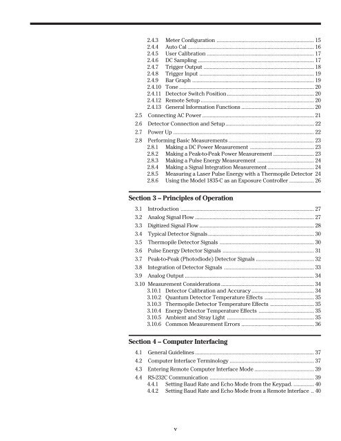
2.4.3 Meter Configuration ................................................................... 15<br />
2.4.4 Auto Cal ....................................................................................... 16<br />
2.4.5 User Calibration .......................................................................... 17<br />
2.4.6 DC Sampling ................................................................................ 17<br />
2.4.7 Trigger Output ............................................................................ 18<br />
2.4.8 Trigger Input ............................................................................... 19<br />
2.4.9 Bar Graph .................................................................................... 19<br />
2.4.10 Tone ............................................................................................. 20<br />
2.4.11 Detector Switch Position............................................................ 20<br />
2.4.12 Remote Setup .............................................................................. 20<br />
2.4.13 General Information Functions .................................................. 20<br />
2.5 Connecting AC Power ............................................................................. 21<br />
2.6 Detector Connection and Setup............................................................. 22<br />
2.7 Power Up ................................................................................................. 22<br />
2.8 Performing Basic Measurements ........................................................... 23<br />
2.8.1 Making a DC Power Measurement ............................................ 23<br />
2.8.2 Making a Peak-to-Peak Power Measurement ............................ 23<br />
2.8.3 Making a Pulse Energy Measurement ....................................... 24<br />
2.8.4 Making a Signal Integration Measurement................................ 24<br />
2.8.5 Measuring a Laser Pulse Energy with a Thermopile Detector 24<br />
2.8.6 Using the <strong>Model</strong> <strong>1835</strong>-C as an Exposure Controller ................. 26<br />
Section 3 – Principles of Operation<br />
3.1 Introduction ............................................................................................ 27<br />
3.2 Analog Signal Flow .................................................................................. 27<br />
3.3 Digitized Signal Flow ............................................................................... 28<br />
3.4 Typical Detector Signals......................................................................... 30<br />
3.5 Thermopile Detector Signals ................................................................. 30<br />
3.6 Pulse Energy Detector Signals ............................................................... 31<br />
3.7 Peak-to-Peak (Photodiode) Detector Signals ........................................ 32<br />
3.8 Integration of Detector Signals .............................................................. 33<br />
3.9 Analog Output ......................................................................................... 34<br />
3.10 Measurement Considerations ................................................................ 34<br />
3.10.1 Detector Calibration and Accuracy ........................................... 34<br />
3.10.2 Quantum Detector Temperature Effects .................................. 35<br />
3.10.3 Thermopile Detector Temperature Effects .............................. 35<br />
3.10.4 Energy Detector Temperature Effects ...................................... 35<br />
3.10.5 Ambient and Stray Light ............................................................ 35<br />
3.10.6 Common Measurement Errors .................................................. 36<br />
Section 4 – Computer Interfacing<br />
4.1 General Guidelines .................................................................................. 37<br />
4.2 Computer Interface Terminology .......................................................... 37<br />
4.3 Entering Remote Computer Interface Mode ......................................... 39<br />
4.4 RS-232C Communication ........................................................................ 39<br />
4.4.1 Setting Baud Rate and Echo Mode from the Keypad. .............. 40<br />
4.4.2 Setting Baud Rate and Echo Mode from a Remote Interface .. 40<br />
v


