- Page 1 and 2: Service. Workshop Manual VW Marine
- Page 3 and 4: 10 Removing and installing engine P
- Page 5 and 6: 20 Fuel supply system Page Parts of
- Page 7 and 8: 27 Starter, Current supply Page Sta
- Page 9 and 10: Safety Precautions and Technical Da
- Page 11 and 12: Open the cap of the cooling system
- Page 13 and 14: Technical Data Engine number The en
- Page 15 and 16: Code letters BCU ANG BCV ANH Manufa
- Page 17 and 18: Note: General information on self-d
- Page 19 and 20: Connecting fault reader All functio
- Page 21 and 22: Vehicle system test Enter address w
- Page 23 and 24: Procedure VAS 5052 - Unscrew the co
- Page 25 and 26: Fault memory Interrogate fault memo
- Page 27 and 28: Erase fault memory Special tools, w
- Page 29 and 30: Fault table Notes: ♦ The fault ta
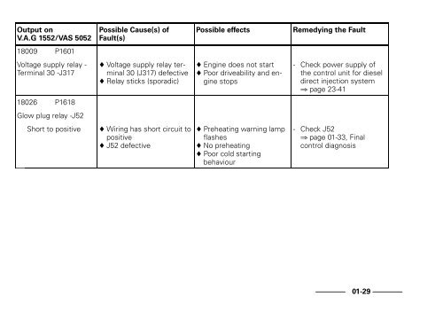
- Page 31 and 32: Output on V.A.G 1552/VAS 5052 16989
- Page 33 and 34: Output on V.A.G 1552/VAS 5052 17568
- Page 35 and 36: Output on V.A.G 1552/VAS 5052 17653
- Page 37 and 38: Output on V.A.G 1552/VAS 5052 17659
- Page 39 and 40: Output on V.A.G 1552/VAS 5052 17663
- Page 41 and 42: Output on V.A.G 1552/VAS 5052 17946
- Page 43: Output on V.A.G 1552/VAS 5052 17978
- Page 47 and 48: Output on V.A.G 1552/VAS 5052 18047
- Page 49 and 50: Rapid data transfer Select function
- Page 51 and 52: Rapid data transfer Select function
- Page 53 and 54: Rapid data transfer Select function
- Page 55 and 56: Evaluate measuring value blocks at
- Page 57 and 58: Evaluation: Display of injection qu
- Page 59 and 60: Evaluation: Display of accelerator
- Page 61 and 62: Evaluation: Display of commencement
- Page 63 and 64: Display group 007 with ignition on
- Page 65 and 66: Display group 013 at idling (warm e
- Page 67 and 68: Evaluation: Display of idle running
- Page 69 and 70: Display group 19 with ignition on D
- Page 71 and 72: Display group 125 at idle Display g
- Page 73 and 74: Display group 000 (display values,
- Page 75 and 76: Evaluation: Display of commencement
- Page 77 and 78: Evaluation: Display of injection qu
- Page 79 and 80: Engine code letters ANG, BCU Displa
- Page 81 and 82: Display group 004 at full load (tes
- Page 83 and 84: Evaluation: Display of commencement
- Page 85 and 86: Engine code letters ANH, BCV Displa
- Page 87 and 88: Display group 010 at full load (tes
- Page 89 and 90: VW 313 3033 V.A.G 1332 VW 540 V.A.G
- Page 91 and 92: - Screw the central plug of the ins
- Page 93 and 94: - Unscrew the throttle linkage -1-
- Page 95 and 96:
3033 - Hook in the lifting tackle 3
- Page 97 and 98:
Engine with power steering pump - I
- Page 99 and 100:
1 2 Gearbox bell for reversing gear
- Page 101 and 102:
I III II IV Dismantling and assembl
- Page 103 and 104:
1 2 3 4 5 6 7 8 9 10 Part I 1 - Dus
- Page 105 and 106:
1 2 3 4 5 6 7 8 9 10 15 - Washer
- Page 107 and 108:
1 2 3 4 5 6 7 8 9 4-Camshaftsprocke
- Page 109 and 110:
1 2 3 4 5 6 Part III 26 25 24 23 7
- Page 111 and 112:
26 25 24 23 1 2 3 4 5 6 7 8 9 10 11
- Page 113 and 114:
1 2 3 4 5 6 23 - Cup packing ♦ Re
- Page 115 and 116:
1 2 3 4 5 6 7 8 9 10 11 12 13 14 6
- Page 117 and 118:
1 2 3 4 5 6 7 8 17 - 20 Nm ♦ M8,
- Page 119 and 120:
Belt drive without power steering p
- Page 121 and 122:
3 4 5 6 7 8 9 10 11 12 Removing and
- Page 123 and 124:
3 4 5 6 7 8 9 10 11 12 16 - Cylinde
- Page 125 and 126:
1 2 - Unscrew the bolts -arrows- fr
- Page 127 and 128:
Removing - Remove toothed belt for
- Page 129 and 130:
Fitting Note: The oil seal of the s
- Page 131 and 132:
1 2 3 4 5 6 4-65Nm 2 1 2 3 4 5 6 7
- Page 133 and 134:
Crankshaft dimensions (Dimensions i
- Page 135 and 136:
11 2 1 2 3 4 3 - Piston ♦ Mark in
- Page 137 and 138:
11 2 1 2 3 4 9 - Bearing shell ♦
- Page 139 and 140:
Fig. 2 Checking piston-ring height
- Page 141 and 142:
Fig. 4 Piston installation position
- Page 143 and 144:
Test procedure VW382/7 VW385/17 Whe
- Page 145 and 146:
31 30 29 28 27 26 25 24 23 22 1 2 3
- Page 147 and 148:
31 30 29 28 27 1 2 3 4 5 6 7 6 - Dr
- Page 149 and 150:
31 30 29 28 1 2 3 4 5 20 - Toothed
- Page 151 and 152:
31 30 29 28 27 26 25 24 23 22 1 2 3
- Page 153 and 154:
2065 A 2068 A Removing and installi
- Page 155 and 156:
- Remove the tensioner for the ribb
- Page 157 and 158:
A 2068 A Engine removed: - Set adju
- Page 159 and 160:
- Centre adjustment ruler as follow
- Page 161 and 162:
However, if it is accidentally turn
- Page 163 and 164:
- Toothed belt for injection pump
- Page 165 and 166:
Preconditions The engine may be a m
- Page 167 and 168:
9 5 3 1 7 11 - Tighten cylinder hea
- Page 169 and 170:
Test condition Engine oil temperatu
- Page 171 and 172:
19 1 2 1 3 4 5 6 7 8 9 10 11 12 13
- Page 173 and 174:
1 2 1 3 8 - Valve stem seal ♦ Ren
- Page 175 and 176:
VW 387 Fig. 1 Checking camshaft, ax
- Page 177 and 178:
Fig. 4 Camshaft marking, valve timi
- Page 179 and 180:
- Measure distance -a- between valv
- Page 181 and 182:
VW387 Test procedure - Insert new v
- Page 183 and 184:
2036 10 -204 3047 A VW 541/1A Renew
- Page 185 and 186:
A B 10 - 204 Fitting - To prevent d
- Page 187 and 188:
Checking hydraulic bucket tappets S
- Page 189 and 190:
Removing and installing parts of lu
- Page 191 and 192:
1 2 3 4 5 6 7 8 9 10 11 10 Part I 1
- Page 193 and 194:
1 2 3 4 5 6 7 8 9 10 11 10 8-Camsha
- Page 195 and 196:
1 2 3 4 5 6 7 8 9 10 18 11 12 13 14
- Page 197 and 198:
1 2 3 4 5 6 7 8 9 10 18 11 12 13 14
- Page 199 and 200:
32 31 30 1 2 3 10 - 10 Nm 11 - 20 N
- Page 201 and 202:
32 31 30 1 2 3 24 - Hollow screw, 3
- Page 203 and 204:
1 2 3 8 - Retaining clip 9-20Nm 28
- Page 205 and 206:
1 2 3 25 - Oil return line 28 4 5 2
- Page 207 and 208:
- Unscrew the oil sump. - If necess
- Page 209 and 210:
Note: After fitting the oil sump, t
- Page 211 and 212:
V.A.G 1342 Note: Operating test and
- Page 213 and 214:
Removing and installing parts of co
- Page 215 and 216:
29 28 1 2 3 4 5 6 7 8 9 Parts of co
- Page 217 and 218:
1 2 3 14 - Connecting hose 29 28 4
- Page 219 and 220:
1 2 3 28 - 20 Nm 29 28 4 5 6 7 8 9
- Page 221 and 222:
Fig. 3 Installing housing-radiator
- Page 223 and 224:
1 2 3 4 5 6 7 9 - Seawater filter h
- Page 225 and 226:
1 2 3 4 5 - Connection piece 22 21
- Page 227 and 228:
1 2 3 4 16 - Retaining clip ♦ che
- Page 229 and 230:
1 2 3 4 5 7 - Locking ball 8 24 22
- Page 231 and 232:
1 2 3 4 5 21 - 20 Nm 8 24 22 23 6 2
- Page 233 and 234:
7 7 - Exhaust-pipe connection piece
- Page 235 and 236:
7 6 8 11 - Oil cooler 12 - Coolant
- Page 237 and 238:
7 6 8 10 - Cylinder block 11 - Oil
- Page 239 and 240:
Draining - Open cap of housing-radi
- Page 241 and 242:
Recommended mixing ratio: Antifreez
- Page 243 and 244:
Removing Notes: ♦ Always renew ga
- Page 245 and 246:
1 2 Fitting Installation is carried
- Page 247 and 248:
1 2 - Lever the rubber protection c
- Page 249 and 250:
Parts of fuel supply Dismantling an
- Page 251 and 252:
33 32 31 30 29 28 27 26 24 23 22 20
- Page 253 and 254:
33 32 31 30 29 28 27 26 24 23 22 20
- Page 255 and 256:
1 3 1 4 2 5 Servicing the Fuel Filt
- Page 257 and 258:
Safety precautions when working on
- Page 259 and 260:
1 10 9 2 1 3 4 Servicing throttle c
- Page 261 and 262:
V.A.G 1526 A V.A.G 1552 V.A.G 1594
- Page 263 and 264:
Read measuring value block 2 → rp
- Page 265 and 266:
- Separate the 6-pin connector for
- Page 267 and 268:
Adjusting accelerator lever positio
- Page 269 and 270:
1 - Tighten the mounting screws -ar
- Page 271 and 272:
33 1 2 3 4 3 5 6 1 - To intake mani
- Page 273 and 274:
33 1 2 3 4 3 5 6 7 21 - Gasket ♦
- Page 275 and 276:
1 2 3 4 5 6 Removing and installing
- Page 277 and 278:
1 2 3 4 5 6 13 - To housing-radiato
- Page 279 and 280:
Removing and installing turbocharge
- Page 281 and 282:
- Disconnect the air filter hose -a
- Page 283 and 284:
- Unscrew the lower mounting bolts
- Page 285 and 286:
- Position the oil supply line -arr
- Page 287 and 288:
1 - Disconnect the connection hoses
- Page 289 and 290:
Fitting Installation is carried out
- Page 291 and 292:
Rapid data transfer Select function
- Page 293 and 294:
Check the function of the pressure
- Page 295 and 296:
Rules regarding cleanliness Always
- Page 297 and 298:
1 2 3 4 5 6 7 8 SUPERIOR MARINE TEC
- Page 299 and 300:
1 2 3 4 5 6 Fuse box/relay plate 1
- Page 301 and 302:
1 2 3 4 5 6 13 - Glow plug relay (J
- Page 303 and 304:
1 2 3 4 5 Removing and installing t
- Page 305 and 306:
1 2 3 4 3 5 6 7 3 8 3 9 10 11 Servi
- Page 307 and 308:
16 29 28 27 26 25 5 6 7 3 1 2 3 4 3
- Page 309 and 310:
5 6 7 3 29 - 25 Nm 1 2 3 4 3 8 3 9
- Page 311 and 312:
2068 A 3313 V.A.G 1332 3036 V.A.G 1
- Page 313 and 314:
- Screw the TDC sender T 01901 into
- Page 315 and 316:
- Place the toothed belt on the inj
- Page 317 and 318:
Note: If the front pointer is outsi
- Page 319 and 320:
3035 ♦ 3035 Ring spanner ♦ T 01
- Page 321 and 322:
- Unscrew the securing screws -1- a
- Page 323 and 324:
Blocking injection pump from delive
- Page 325 and 326:
Notes: ♦ The dynamic test and cor
- Page 327 and 328:
Note: ♦ During the check, if the
- Page 329 and 330:
Defective nozzles can be detected b
- Page 331 and 332:
Checking injection pressure Importa
- Page 333 and 334:
- Install the fuse box/relay plate:
- Page 335 and 336:
1 Test procedure - Open the cover -
- Page 337 and 338:
- Check the cable connections to th
- Page 339 and 340:
4 5 81 62 63 44 24 43 6 25 Check vo
- Page 341 and 342:
Test procedure - Pull the plug off
- Page 343 and 344:
V.A.G 1526 A V.A.G 1552 V.A.G 1594
- Page 345 and 346:
Note: Depending on the weather, the
- Page 347 and 348:
V.A.G 1526 A V.A.G 1552 V.A.G 1594
- Page 349 and 350:
- If there is no realistic display
- Page 351 and 352:
2 4 A - Check the wires between plu
- Page 353 and 354:
Rapid data transfer Select function
- Page 355 and 356:
7000 6000 5000 4000 3000 2000 A B 9
- Page 357 and 358:
V.A.G 1526 A V.A.G 1552 V.A.G 1594
- Page 359 and 360:
- Switch off the ignition. - Separa
- Page 361 and 362:
1 3 5 7 9 A 2 4 6 8 10 1 2 98 105 1
- Page 363 and 364:
V.A.G 1526 A V.A.G 1552 V.A.G 1594
- Page 365 and 366:
Checking the Modulating Piston Move
- Page 367 and 368:
- Separate the 10-pin connector for
- Page 369 and 370:
Checking the Needle Lift Sender V.A
- Page 371 and 372:
A 98 105 2 1 - Check the wires betw
- Page 373 and 374:
Rapid data transfer Select function
- Page 375 and 376:
10 8 6 4 2 - Measure resistance bet
- Page 377 and 378:
V.A.G 1526 A V.A.G 1552 V.A.G 1594
- Page 379 and 380:
- Press the → -button. - Press ke
- Page 381 and 382:
Engine control unit Renewing engine
- Page 383 and 384:
- Pull the relay -1- out of the soc
- Page 385 and 386:
Test procedure - Remove the engine
- Page 387 and 388:
1 2 3 4 Exhaust system without turb
- Page 389 and 390:
1 2 3 6-40Nm ♦ Allen screw 7-Gask
- Page 391 and 392:
Removing and installing starter V.A
- Page 393 and 394:
- Unscrew the mounting screws -arro
- Page 395 and 396:
A A Removing and installing voltage
- Page 397 and 398:
3310 ♦ 3310 Socket head W00--0299
- Page 399 and 400:
Alternator brackets and ribbed V-be
- Page 401 and 402:
14 12 13 12 1 2 3 5 - Hexagon bolts
- Page 403 and 404:
1 2 9 8 1 10 9 8 7 6 Y27--0005 Y27-
- Page 405 and 406:
11 10 1 2 3 9 8 Y27--0008 4 5 6 7 F
- Page 407 and 408:
Removing ribbed V-belt of alternato
- Page 409 and 410:
Belt drive with alternator and addi
- Page 411 and 412:
Additional 230 V alternator Importa
- Page 413 and 414:
7 - Washers (8 mm x 25 mm) 1 2 3 4
- Page 415 and 416:
Installing: Installation is carried
- Page 417 and 418:
- Unscrew the two mounting screws -
- Page 419 and 420:
The red LED lights up: ♦ Undervol
- Page 421 and 422:
Test procedure - Remove the connect
- Page 423 and 424:
Test procedure - Remove the engine
- Page 425 and 426:
1 2 Function overview: Power steeri
- Page 427 and 428:
1 2 Exploded view: Power steering p
- Page 429 and 430:
1 2 11 - Seal ♦ Renew 12 - Screw
- Page 431 and 432:
- Start engine and top up oil level
- Page 433 and 434:
1 1 2 - Unscrew bolts -1- and -2-.
- Page 435 and 436:
Removing and installing individual
- Page 437 and 438:
Fuse box/relay plate Removing and i
- Page 439 and 440:
- Unscrew the upper mounting screws
- Page 441 and 442:
A B C D E F G N O M P L K J R H Y97
- Page 443 and 444:
J H G F P N K v u t s r p n m a b c
- Page 445 and 446:
J H G F E Z X W V f e d c b a s r p
- Page 447 and 448:
Removing and installing earth switc
- Page 449 and 450:
A B - Remove the support -A- togeth
- Page 451 and 452:
Wiring loom between instrument pane
- Page 453:
Repair instructions for wiring loom