

ML193DF Gas Furnace Installation Manual - Lennox
ML193DF Gas Furnace Installation Manual - Lennox
ML193DF Gas Furnace Installation Manual - Lennox

You also want an ePaper? Increase the reach of your titles
YUMPU automatically turns print PDFs into web optimized ePapers that Google loves.
Intake Piping<br />
The <strong>ML193DF</strong> furnace may be installed in either direct<br />
vent or non−direct vent applications. In non−direct vent<br />
applications, when intake air will be drawn into the furnace<br />
from the surrounding space, the indoor air quality must be<br />
considered. Guidelines listed in Combustion, Dilution and<br />
Ventilation Air section must be followed.<br />
Follow the next two steps when installing the unit in Direct<br />
Vent applications, where combustion air is taken from<br />
outdoors and flue gases are discharged outdoors. The<br />
provided air intake screen must not be used in direct<br />
vent applications (outdoors).<br />
1 − Use cement to secure the intake pipe to the inlet air<br />
connector.<br />
2 − Route piping to outside of structure. Continue with<br />
installation following instructions given in general<br />
guide lines for piping terminations and intake and exhaust<br />
piping terminations for direct vent sections. Refer<br />
to table 7 for pipe sizes.<br />
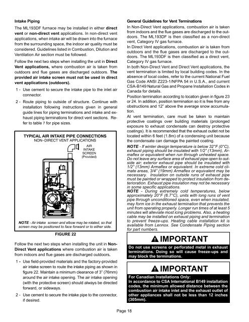
TYPICAL AIR INTAKE PIPE CONNECTIONS<br />
NON−DIRECT VENT APPLICATIONS<br />
FIGURE 22<br />
AIR<br />
INTAKE<br />
SCREEN<br />
(Provided)<br />
NOTE − Air intake screen and elbow may be rotated, so that<br />
screen may be positioned to face forward or to either side.<br />
Follow the next two steps when installing the unit in Non-<br />
Direct Vent applications where combustion air is taken<br />
from indoors and flue gases are discharged outdoors.<br />
1 − Use field−provided materials and the factory−provided<br />
air intake screen to route the intake piping as shown in<br />
figure 22. Maintain a minimum clearance of 3" (76mm)<br />
around the air intake opening. The air intake opening<br />
(with the protective screen) should always be directed<br />
forward, or sideways.<br />
2 − Use cement to secure the intake pipe to the connector,<br />
if desired.<br />
General Guidelines for Vent Terminations<br />
In Non-Direct Vent applications, combustion air is taken<br />
from indoors and the flue gases are discharged to the outdoors.<br />
The <strong>ML193DF</strong> is then classified as a non-direct<br />
vent, Category IV gas furnace.<br />
In Direct Vent applications, combustion air is taken from<br />
outdoors and the flue gases are discharged to the outdoors.<br />
The <strong>ML193DF</strong> is then classified as a direct vent,<br />
Category IV gas furnace.<br />
In both Non-Direct Vent and Direct Vent applications, the<br />
vent termination is limited by local building codes. In the<br />
absence of local codes, refer to the current National Fuel<br />
<strong>Gas</strong> Code ANSI Z223−1/NFPA 54 in U.S.A., and current<br />
CSA−B149 Natural <strong>Gas</strong> and Propane <strong>Installation</strong> Codes in<br />
Canada for details.<br />
Position termination according to location given in figure 23<br />
or 24. In addition, position termination so it is free from any<br />
obstructions and 12" above the average snow accumulation.<br />
At vent termination, care must be taken to maintain<br />
protective coatings over building materials (prolonged<br />
exposure to exhaust condensate can destroy protective<br />
coatings). It is recommended that the exhaust outlet not be<br />
located within 6 feet (1.8m) of a condensing unit because<br />
the condensate can damage the painted coating.<br />
NOTE − If winter design temperature is below 32°F (0°C),<br />
exhaust piping should be insulated with 1/2" (13mm), Armaflex<br />
or equivalent when run through unheated space.<br />
Do not leave any surface area of exhaust pipe open to outside<br />
air; exterior exhaust pipe should be insulated with<br />
1/2" (13mm) Armaflex or equivalent. In extreme cold climate<br />
areas, 3/4" (19mm) Armaflex or equivalent may be<br />
necessary. Insulation on outside runs of exhaust pipe<br />
must be painted or wrapped to protect insulation from deterioration.<br />
Exhaust pipe insulation may not be necessary<br />
in some specific applications.<br />
NOTE − During extremely cold temperatures, below<br />
approximately 20°F (6.7°C), units with long runs of vent<br />
pipe through unconditioned space, even when insulated,<br />
may form ice in the exhaust termination that prevents the<br />
unit from operating properly. Longer run times of at least 5<br />
minutes will alleviate most icing problems. Also, a heating<br />
cable may be installed on exhaust piping and termination<br />
to prevent freeze−ups. Heating cable installation kit is<br />
available from <strong>Lennox</strong>. See Condensate Piping section<br />
for part numbers.<br />
IMPORTANT<br />
Do not use screens or perforated metal in exhaust<br />
terminations. Doing so will cause freeze−ups and<br />
may block the terminations.<br />
IMPORTANT<br />
For Canadian <strong>Installation</strong>s Only:<br />
In accordance to CSA International B149 installation<br />
codes, the minimum allowed distance between the<br />
combustion air intake inlet and the exhaust outlet of<br />
other appliances shall not be less than 12 inches<br />
(305mm).<br />
Page 18


