

ML193DF Gas Furnace Installation Manual - Lennox
ML193DF Gas Furnace Installation Manual - Lennox
ML193DF Gas Furnace Installation Manual - Lennox

You also want an ePaper? Increase the reach of your titles
YUMPU automatically turns print PDFs into web optimized ePapers that Google loves.
<strong>Gas</strong> Piping<br />
CAUTION<br />
If a flexible gas connector is required or allowed by<br />
the authority that has jurisdiction, black iron pipe<br />
shall be installed at the gas valve and extend outside<br />
the furnace cabinet. The flexible connector can then<br />
be added between the black iron pipe and the gas<br />
supply line.<br />
WARNING<br />
Do not exceed 600 in−lbs (50 ft−lbs) torque when attaching<br />
the gas piping to the gas valve.<br />
1 − <strong>Gas</strong> piping may be routed into the unit through either<br />
the left- or right-hand side. Supply piping enters into<br />
the gas valve from the side of the valve as shown in<br />
figure 47.<br />
2 − When connecting gas supply, factors such as length of<br />
run, number of fittings and furnace rating must be considered<br />
to avoid excessive pressure drop. Table 10<br />
lists recommended pipe sizes for typical applications.<br />
NOTE − Use two wrenches when connecting gas piping<br />
to avoid transferring torque to the manifold.<br />
3 − <strong>Gas</strong> piping must not run in or through air ducts, clothes<br />
chutes, chimneys or gas vents, dumb waiters or elevator<br />
shafts. Center gas line through piping hole. <strong>Gas</strong><br />
line should not touch side of unit. See figures 47.<br />
4 − Piping should be sloped 1/4 inch per 15 feet (6mm per<br />
5.6m) upward toward the gas meter from the furnace.<br />
The piping must be supported at proper intervals, every<br />
8 to 10 feet (2.44 to 3.05m), using suitable hangers<br />
or straps. Install a drip leg in vertical pipe runs to serve as<br />
a trap for sediment or condensate.<br />
5 − A 1/8" N.P.T. plugged tap or pressure post is located<br />
on the gas valve to facilitate test gauge connection.<br />
See figure 54.<br />
6 − In some localities, codes may require installation of a<br />
manual main shut-off valve and union (furnished by installer)<br />
external to the unit. Union must be of the<br />
ground joint type.<br />
IMPORTANT<br />
Compounds used on threaded joints of gas piping<br />
must be resistant to the actions of liquified petroleum<br />
gases.<br />
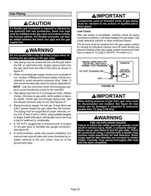
Leak Check<br />
After gas piping is completed, carefully check all piping<br />
connections (factory− and field−installed) for gas leaks. Use<br />
a leak detecting solution or other preferred means.<br />
The furnace must be isolated from the gas supply system<br />
by closing its individual manual shut-off valve during any<br />
pressure testing of the gas supply system at pressures less<br />
than or equal to 1/2 psig (3.48 kPa, 14 inches w.c.).<br />
MANUAL MAIN SHUT−OFF<br />
VALVE WILL NOT HOLD<br />
NORMAL TEST PRESSURE<br />
1/8" N.P.T. PLUGGED TAP<br />
CAP<br />
FIGURE 46<br />
FURNACE<br />
ISOLATE<br />
GAS VALVE<br />
IMPORTANT<br />
When testing pressure of gas lines, gas valve must<br />
be disconnected and isolated. See figure 46. <strong>Gas</strong><br />
valves can be damaged if subjected to pressures<br />
greater than 1/2 psig (3.48 kPa).<br />
WARNING<br />
FIRE OR EXPLOSION HAZARD<br />
Failure to follow the safety warnings exactly could<br />
result in serious injury, death, or property damage.<br />
Never use an open flame to test for gas leaks. Check<br />
all connections using a commercially available soap<br />
solution made specifically for leak detection. Some<br />
soaps used for leak detection are corrosive to certain<br />
metals. Carefully rinse piping thoroughly after leak<br />
test has been completed.<br />
Page 30


