

ML193DF Gas Furnace Installation Manual - Lennox
ML193DF Gas Furnace Installation Manual - Lennox
ML193DF Gas Furnace Installation Manual - Lennox

Create successful ePaper yourself
Turn your PDF publications into a flip-book with our unique Google optimized e-Paper software.
Other Unit Adjustments<br />
NOTE − See troubleshooting flow charts if any safety<br />
switches are found to be open.<br />
Primary Limit<br />
The primary limit is located on the heating compartment<br />
vestibule panel. This limit is factory set and requires no adjustment.<br />
Flame Rollout Switches (Two)<br />
These manually reset switches are located on the front of<br />
the burner box.<br />
Pressure Switch<br />
The pressure switch is located in the heating compartment<br />
on the cold end header box. This switch checks for proper<br />
combustion air inducer operation before allowing ignition<br />
trial. The switch is factory−set and must not be adjusted.<br />
Temperature Rise<br />
After the furnace has been started and supply and return air<br />
temperatures have been allowed to stabilize, check the<br />
temperature rise. If necessary, adjust the blower speed to<br />
maintain the temperature rise within the range shown on<br />
the unit nameplate. Increase the blower speed to decrease<br />
the temperature. Decrease the blower speed to increase<br />
the temperature rise. Failure to adjust the temperature rise<br />
may cause erratic limit operation.<br />
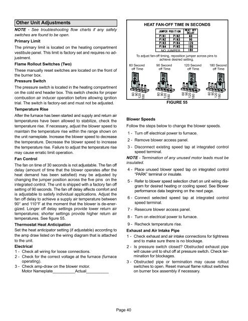
Fan Control<br />
The fan on time of 30 seconds is not adjustable. The fan off<br />
delay (amount of time that the blower operates after the<br />
heat demand has been satisfied) may be adjusted by<br />
changing the jumper position across the five pins on the<br />
integrated control. The unit is shipped with a factory fan off<br />
setting of 90 seconds. The fan off delay affects comfort and<br />
is adjustable to satisfy individual applications. Adjust the<br />
fan off delay to achieve a supply air temperature between<br />
90° and 110°F at the moment that the blower is de−energized.<br />
Longer off delay settings provide lower return air<br />
temperatures; shorter settings provide higher return air<br />
temperatures. See figure 55.<br />
Thermostat Heat Anticipation<br />
Set the heat anticipator setting (if adjustable) according to<br />
the amp draw listed on the wiring diagram that is attached<br />
to the unit.<br />
Electrical<br />
1 − Check all wiring for loose connections.<br />
2 − Check for the correct voltage at the furnace (furnace<br />
operating).<br />
3 − Check amp-draw on the blower motor.<br />
Motor Nameplate__________Actual__________<br />
HEAT FAN-OFF TIME IN SECONDS<br />
NO JUMPER<br />
To adjust fan−off timing, reposition jumper across pins to<br />
achieve desired setting.<br />
60 Second<br />
off Time<br />
60<br />
90<br />
120<br />
180<br />
90 Second<br />
off Time<br />
60<br />
90<br />
120<br />
180<br />
FIGURE 55<br />
120 Second<br />
off Time<br />
60<br />
90<br />
120<br />
180<br />
180 Second<br />
off Time<br />
60<br />
90<br />
120<br />
180<br />
Blower Speeds<br />
Follow the steps below to change the blower speeds.<br />
1 − Turn off electrical power to furnace.<br />
2 − Remove blower access panel.<br />
3 − Disconnect existing speed tap at integrated control<br />
speed terminal.<br />
NOTE − Termination of any unused motor leads must be<br />
insulated.<br />
4 − Place unused blower speed tap on integrated control<br />
PARK" terminal or insulate.<br />
5 − Refer to blower speed selection chart on unit wiring diagram<br />
for desired heating or cooling speed. See Blower<br />
performance data beginning on the next page.<br />
6 − Connect selected speed tap at integrated control<br />
speed terminal.<br />
7 − Resecure blower access panel.<br />
8 − Turn on electrical power to furnace.<br />
9 − Recheck temperature rise.<br />
Exhaust and Air Intake Pipe<br />
1 − Check exhaust and air intake connections for tightness<br />
and to make sure there is no blockage.<br />
2 − Is pressure switch closed? Obstructed exhaust pipe<br />
will cause unit to shut off at pressure switch. Check termination<br />
for blockages.<br />
3 − Obstructed pipe or termination may cause rollout<br />
switches to open. Reset manual flame rollout switches<br />
on burner box assembly if necessary.<br />
Page 40


