

ML193DF Gas Furnace Installation Manual - Lennox
ML193DF Gas Furnace Installation Manual - Lennox
ML193DF Gas Furnace Installation Manual - Lennox

Create successful ePaper yourself
Turn your PDF publications into a flip-book with our unique Google optimized e-Paper software.
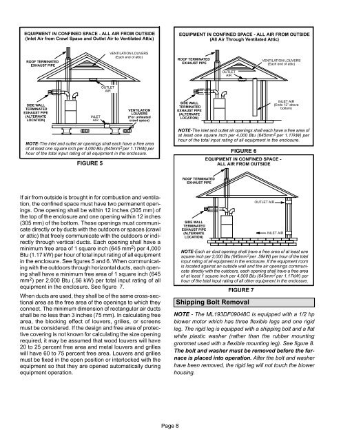
EQUIPMENT IN CONFINED SPACE − ALL AIR FROM OUTSIDE<br />
(Inlet Air from Crawl Space and Outlet Air to Ventilated Attic)<br />
EQUIPMENT IN CONFINED SPACE − ALL AIR FROM OUTSIDE<br />
(All Air Through Ventilated Attic)<br />
ROOF TERMINATED<br />
EXHAUST PIPE<br />
VENTILATION LOUVERS<br />
(Each end of attic)<br />
ROOF TERMINATED<br />
EXHAUST PIPE<br />
VENTILATION LOUVERS<br />
(Each end of attic)<br />
OUTLET<br />
AIR<br />
OUTLET<br />
AIR<br />
SIDE WALL<br />
TERMINATED<br />
EXHAUST PIPE<br />
(ALTERNATE<br />
LOCATION)<br />
INLET<br />
AIR<br />
VENTILATION<br />
LOUVERS<br />
(For unheated<br />
crawl space)<br />
SIDE WALL<br />
TERMINATED<br />
EXHAUST PIPE<br />
(ALTERNATE<br />
LOCATION)<br />
INLET AIR<br />
(Ends 12" above<br />
bottom)<br />
NOTE−The inlet and outlet air openings shall each have a free area<br />
of at least one square inch per 4,000 Btu (645mm 2 per 1.17kW) per<br />
hour of the total input rating of all equipment in the enclosure.<br />
FIGURE 5<br />
NOTE−The inlet and outlet air openings shall each have a free area of<br />
at least one square inch per 4,000 Btu (645mm 2 per 1.17kW) per<br />
hour of the total input rating of all equipment in the enclosure.<br />
FIGURE 6<br />
EQUIPMENT IN CONFINED SPACE −<br />
ALL AIR FROM OUTSIDE<br />
ROOF TERMINATED<br />
EXHAUST PIPE<br />
If air from outside is brought in for combustion and ventilation,<br />
the confined space must have two permanent openings.<br />
One opening shall be within 12 inches (305 mm) of<br />
the top of the enclosure and one opening within 12 inches<br />
(305 mm) of the bottom. These openings must communicate<br />
directly or by ducts with the outdoors or spaces (crawl<br />
or attic) that freely communicate with the outdoors or indirectly<br />
through vertical ducts. Each opening shall have a<br />
minimum free area of 1 square inch (645 mm 2 ) per 4,000<br />
Btu (1.17 kW) per hour of total input rating of all equipment<br />
in the enclosure. See figures 5 and 6. When communicating<br />
with the outdoors through horizontal ducts, each opening<br />
shall have a minimum free area of 1 square inch (645<br />
mm 2 ) per 2,000 Btu (.56 kW) per total input rating of all<br />
equipment in the enclosure. See figure 7.<br />
When ducts are used, they shall be of the same cross−sectional<br />
area as the free area of the openings to which they<br />
connect. The minimum dimension of rectangular air ducts<br />
shall be no less than 3 inches (75 mm). In calculating free<br />
area, the blocking effect of louvers, grilles, or screens<br />
must be considered. If the design and free area of protective<br />
covering is not known for calculating the size opening<br />
required, it may be assumed that wood louvers will have<br />
20 to 25 percent free area and metal louvers and grilles<br />
will have 60 to 75 percent free area. Louvers and grilles<br />
must be fixed in the open position or interlocked with the<br />
equipment so that they are opened automatically during<br />
equipment operation.<br />
SIDE WALL<br />
TERMINATED<br />
EXHAUST PIPE<br />
(ALTERNATE<br />
LOCATION)<br />
FIGURE 7<br />
OUTLET AIR<br />
INLET AIR<br />
NOTE−Each air duct opening shall have a free area of at least one<br />
square inch per 2,000 Btu (645mm 2 per .59kW) per hour of the total<br />
input rating of all equipment in the enclosure. If the equipment room<br />
is located against an outside wall and the air openings communicate<br />
directly with the outdoors, each opening shall have a free area<br />
of at least 1 square inch per 4,000 Btu (645mm 2 per 1.17kW) per<br />
hour of the total input rating of all other equipment in the enclosure.<br />
Shipping Bolt Removal<br />
NOTE − The <strong>ML193DF</strong>09048C is equipped with a 1/2 hp<br />
blower motor which has three flexible legs and one rigid<br />
leg. The rigid leg is equipped with a shipping bolt and a flat<br />
white plastic washer (rather than the rubber mounting<br />
grommet used with a flexible mounting leg). See figure 8.<br />
The bolt and washer must be removed before the furnace<br />
is placed into operation. After the bolt and washer<br />
have been removed, the rigid leg will not touch the blower<br />
housing.<br />
Page 8


