Royal Aircraft Factory SE5a Manual - Macca's Vintage Aerodrome
Royal Aircraft Factory SE5a Manual - Macca's Vintage Aerodrome
Royal Aircraft Factory SE5a Manual - Macca's Vintage Aerodrome

Create successful ePaper yourself
Turn your PDF publications into a flip-book with our unique Google optimized e-Paper software.
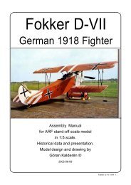
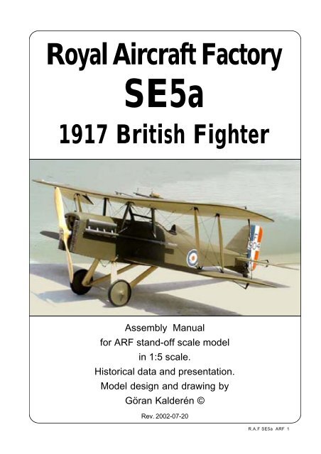
<strong>Royal</strong> <strong>Aircraft</strong> <strong>Factory</strong><br />
<strong>SE5a</strong><br />
1917 British Fighter<br />
Assembly <strong>Manual</strong><br />
for ARF stand-off scale model<br />
in 1:5 scale.<br />
Historical data and presentation.<br />
Model design and drawing by<br />
Göran Kalderén ©<br />
Rev. 2002-07-20<br />
R.A.F <strong>SE5a</strong> ARF 1
R.A.F <strong>SE5a</strong> ARF 2
<strong>Royal</strong> <strong>Aircraft</strong> <strong>Factory</strong> <strong>SE5a</strong><br />
This fighter scout was developed by<br />
the <strong>Royal</strong> <strong>Aircraft</strong> <strong>Factory</strong> and was to become<br />
a solid weapons platform and at the same<br />
time an agile fighter scout. It became very<br />
popular with the pilots and was to serve long<br />
after the war ended. The construction is quite<br />
simple with a girder trussed fuselage, a staggered<br />
rakish wing design and a reliable control<br />
system.<br />
The armament was normally a fixed,<br />
half enclosed Vickers machinegun and an adjustable<br />
Lewis machinegun on a Foster wing<br />
mount. The latter enabled the pilot to pull down<br />
the weapon for dejamming and/or point the<br />
machine gun in an upward angle to attack the<br />
belly of the opposing aircraft from below.<br />
Powered by a Hispano Suiza 200 hp<br />
or Wolsley Viper 220 hp engine, it had very<br />
good speed and climbing performance.<br />
After the Armistice a large number of<br />
aircraft were used for "skywriting" with smoke.<br />
The exhaust tubes were lengthened and provision<br />
for injecting kerosene or other oil<br />
mictures in the exhaust was provided to produce<br />
white clearly visible smoke.<br />
Our model is painted as the aircraft in<br />
the Shuttleworth collection at Old Warden<br />
aerodrome, Biggleswade, north of London.<br />
The original aircraft is however relatively<br />
sparsely marked, which leaves plenty of options<br />
to decorate the model representing<br />
other individuals. Plenty of documentation is<br />
available from a number of sources like<br />
Albatros Publishing and Squadron /Signals<br />
Publications #69.<br />
R.A.F <strong>SE5a</strong> ARF 3
<strong>Royal</strong> <strong>Aircraft</strong> <strong>Factory</strong> <strong>SE5a</strong><br />
Wingspan: 7.4 m / 24' 4"<br />
Length: 6.4 m / 20' 11"<br />
Heigth: 2.9 m / 9' 6"<br />
Engine: Hispano-Suiza 200 hp<br />
Wolsley Viper 220 hp<br />
Armament: 1 .303 Vickers Machine Gun<br />
1 .303 Lewis Machine Gun<br />
Max speed: 126 mph at 10,000 feet<br />
116 mph at 15,000 feet<br />
Endurance: 2½ hours<br />
Ceiling: 17,000 feet<br />
R.A.F <strong>SE5a</strong> ARF 4
The complete airframe before covering<br />
The Model<br />
We have chosen the scale of 1:5 rendering<br />
a model size that is easy to fly, but also<br />
relatively easy to transport. Both the upper and<br />
the lower wing panels can be removed for transport<br />
which gives very limited requirement for<br />
transportation.<br />
Rudder is controlled by pull-pull cables<br />
from the rudder bar and the elevator by push<br />
rod from the control column. The tailskid is fully<br />
functional and stearable for ease of ground handling<br />
(scale). The elevator has hidden controls<br />
and scale transmission via bellcranks to the elevators.<br />
Lower wing ailerons are controlled by<br />
pushrods from one servo in the fuselage and<br />
the upper ailerons are coupled to the lower with<br />
adjustable link rods.<br />
The prototype was equipped with a Saito<br />
.90 4 cycle engine that gives ample power for<br />
this fighter. With this engine the airplane is capable<br />
of some advanced manoeuvers which you<br />
can demand from a WW1 biplane fighter. The<br />
moment arms are short and the rudders sensitive,<br />
so fly if you can, with a dual rate transmitter.<br />
Specifications:<br />
Wingspan: 63.2” (162 cm)<br />
Length: 51.6” (131 cm)<br />
Wing area: 1622 sq" (101.3 dm²)<br />
Weight: 11 Ibs (5000 g)<br />
Wing load: 16 oz/sq' (49 g/dm²)<br />
Engine: .60 2-stroke -.90 4-stroke<br />
Covering and finish<br />
The model is covered with Solartex and<br />
painted with Dutch Boy enamel from the factory.<br />
When you have made changes in the engine<br />
compartment, you will have to cover the open<br />
areas with fuel proof paint.<br />
Color and markings<br />
There are a number of survivors and we<br />
have chosen to use the colour scheme and<br />
markings of the aircraft in the Shuttleworth collection<br />
at Old Warden, Biggleswade, England.<br />
Other schemes can be made on special request.<br />
Ample documentation is available suggesting<br />
other colour schemes and our model is rather<br />
neutral allowing several attractive additions.<br />
Installation of engine<br />
We recommend that you don’t overpower<br />
this model. The engine mounts have been installed<br />
for the recommended size of engine. It<br />
may be necessary to introduce 2° down and 2°<br />
right thrust of the engine. Should you desire to<br />
install a 4-stroke engine you may have to make<br />
an extension in the engine mount for the<br />
carburator.<br />
2. Drill the holes from the tank to the<br />
carburator, pressure tap and the filling cap.<br />
3. Install the engine and connect the<br />
throttle servo.<br />
4. Make cut outs in the dummy manifold<br />
R.A.F <strong>SE5a</strong> ARF 5
The positions of the rigging wires<br />
The positions of the rigging wires are<br />
marked with heavy lines.<br />
All wires are permanently<br />
attached at<br />
one point<br />
Tailskid, here<br />
uncovered, is<br />
sprung and stearable<br />
Engine radiator<br />
front plus air intake<br />
for carburator gives<br />
good cooling of engine<br />
Elevator is controlled in scale fashion<br />
with linkage in the fuselage<br />
Tailskid is sprung and stearable<br />
R.A.F <strong>SE5a</strong> ARF 6
to allow sufficient airstream around the engine.<br />
5. Re-install the engine cowl using 3 #2<br />
sheet metal screws. The opening in the front of<br />
the radiator should provide adequate cooling but<br />
in case of insufficient air stream this hole may<br />
have to be be widened and enlarged,<br />
Installation of servos, tank, battery and receiver.<br />
The aileron servo is installed in the lower<br />
part of the servo vertical bulkhead under the rudder<br />
bar in the fuselage. The trottle servo elevator<br />
and the rudder servo are installed in the servo<br />
tray. The tank is positioned below the tray at the<br />
side of these servos. Battery pack and receiver<br />
are positioned in the upper part of the tray. The<br />
switch can be mounted on the servo tray with<br />
extension rod or on the instrument panel.<br />
1. Attach a ball link head to joystickand<br />
rudder bar in the appropriate holes. You may<br />
have to enlarge the holes to take the screw from<br />
the ball link (Dubro #189 set of 2).<br />
2. Install the servos for rudder and elevator<br />
and temporarily connect the servo arrns to<br />
the ball links. Neutral position for the elevator is<br />
in line with the stabilizer. Deflection for elevator<br />
is 20° up and down and for rudder 30° right and<br />
left.<br />
Lacing of<br />
bungee<br />
rubber<br />
for the<br />
wheel<br />
shaft<br />
3. Install and connect the throttle servo<br />
in the fashion you prefer.<br />
4. Install the tank in the available space<br />
at the right side under the receiver and battery<br />
tray next to the rudder and throttle servos.<br />
5. Install the aileron servo in the bulkhead.<br />
The aileron push rods attaches to the servo arm<br />
with adjustable clevices or ball links. Deflection<br />
of the ailerons should be 20° up and down.<br />
6. Install the radio switch on the dash<br />
board.<br />
7. Place the receiver and the battery<br />
pack in the upper part of the tray wrapped in<br />
foam rubber and secure with rubber bands.<br />
R.A.F <strong>SE5a</strong> ARF 7
Assembly of the <strong>SE5a</strong><br />
All parts have been assembled at the factory<br />
and only disassembled for transportation.<br />
Rudder and wires are factory adjusted<br />
but may need some tensioning adjustment after<br />
a while. For the elevator a push rod is connected<br />
to the control column. For assembky it is necessary<br />
to attach the pushrod clevices in the rear<br />
of the fuselage to the elevator bellcranks. The<br />
service access hatch has to be removed on both<br />
sides after which the clevices can be attached.<br />
The aileron pushrods are connected to one or<br />
two servos in the bottom of the fuselage. Use<br />
ball links or clevices for this connection as they<br />
have to be removed for lower wing removal.<br />
Assembly of the tail unit<br />
1. Fit the fin to the fuselage with 2 nylon<br />
screws and the screw on top of the fuselage.<br />
2 . Fit the stabilizer halves with elevators<br />
to the fuselage and secure with stabilizer support<br />
wires. Attach the elevator pushrods and<br />
close the two hatches and secure with screws.<br />
3. Attach the rudder with the hinge pins<br />
and connect the rudder wires to the rudder horns.<br />
4. Secure the fin and stabilizer with the<br />
support wires.<br />
5. Check the throw of rudder (30° right<br />
and left) and elevator (20° up and down). Rudder<br />
is actuated by the rudder bar and the elevator<br />
by the joystick.<br />
Assembly of wing panels<br />
1. Push the lower wing halves into the<br />
holes in the fuselage.<br />
2. Push the upper wing halves into the<br />
holes in the wing center cabane. Attach the landing<br />
wires in place. Check the dihedral. Attach<br />
the flying wires in place. See the photos for details.<br />
3. Install the interplane struts. Note that<br />
the approx. 1/8” shorter struts fit in the front positions.<br />
Connect the strut cross bracing by clipping<br />
the kwick links in place.<br />
4. Install the aileron interplane connecting<br />
rods.<br />
5. In the fuselage, connect the aileron<br />
push rods to the servo and check the throw of<br />
the ailerons (20° up and down). For ease in control<br />
you may adjust the servo arms to give differential<br />
throw in which case the up deflection<br />
should be 30°.<br />
6 Mount the upper machine gun support<br />
on the top wing and install the Lewis<br />
machinegun.<br />
Landing gear<br />
Push the landing gear supports in the<br />
holes in the fuselage. Secure with the landing<br />
gear cross bracing and tighten.<br />
Install the wheels on the shaft and secure<br />
with the stoppers. Lace rubber bands in<br />
the fashion shown in the sketch.<br />
This is a very efficient shock absorber.<br />
Balancing<br />
The C/G (center of gravity) or balancing point<br />
should be no further back than approx. 13,5 cm<br />
(5½”) measured from the center of the leading<br />
edge on the upper wing. Make adjustments by<br />
adding wheight if necessary. If you desire a more<br />
groovy and stable flight performance you may<br />
move the C/G as much as 1" (2.5cm) forward.<br />
Flying<br />
Let the engine swing a 14"x6" propeller if possible.<br />
This gives better thrust outside the big radiator<br />
front and reduces sound to a more realistic<br />
level.<br />
Flying characteristic is that of a biplane from<br />
the WW-I period and it will fly happily on 3/4<br />
throttle. Ground handling on a hard surface demands<br />
a gentle hand but on grass surface, the<br />
tailskid provides enough directional stability. During<br />
the initial take off run first keep full up elevator<br />
to keep the tail down. As the speed builds up,<br />
let go gradually of the up elevator and the tail<br />
comes up. You have to compensate for the<br />
torque with right rudder but as the speed builds<br />
up the rudder is returned to neutral. This model<br />
should fly of the ground and not be pulled. Unlike<br />
many other planes from this period this type has<br />
a lifting profile stabilizer that in theory should offset<br />
the climbing tendency of the high lift wing<br />
profile. Once airborn the aircraft is limited aerobatic<br />
like all biplanes from WW 1. Remember<br />
that all turns are made using rudder and elevator<br />
and compensated with aileron!<br />
The landing approach can be rather steep<br />
as per prototype but the flare out needs almost<br />
full up elevator. Once on the ground keep the tail<br />
down to maintain directional stability. In case you<br />
have to make a dead stick landing, keep the nose<br />
down and the speed up. The wires produce a lot<br />
of drag! It is always better to do a good landing<br />
in a bad place than vice versa...<br />
Happy landingsl<br />
R.A.F <strong>SE5a</strong> ARF 8
R.A.F <strong>SE5a</strong> ARF 9
What is in the box:<br />
The ARF kit contains the parts shown in the picture.<br />
All the parts are covered and painted. All the rigging<br />
wires are supplied in the correct lengths and need<br />
only to be clipped to their positions.<br />
9<br />
9<br />
14<br />
12<br />
5<br />
11<br />
11<br />
1<br />
6<br />
7<br />
2<br />
10<br />
6<br />
7<br />
8<br />
1. Fuselage with wing cabane, detachable landing gear.<br />
2. Scale wheels<br />
3. Wing mounted Lewis machinegun<br />
4. Fuselage mounted Vickers machinegun<br />
5. Scale propeller<br />
6. Fin / rudder<br />
7. Stearable tail skid.<br />
8. Stabilizer / elevator<br />
9. Upper wing panels<br />
10. Lower wing panels<br />
11. Interplane struts<br />
12. Aileron connecting rods<br />
13. Wires, turnbuckles and hardware<br />
14. Assembly manual<br />
K&W<br />
Model<br />
Airplanes Inc.<br />
R.A.F <strong>SE5a</strong> ARF 10<br />
P.O.Box 1229, Cebu City Centrl. Postoffice<br />
Cebu City 6000, Philippines<br />
Visiting address:<br />
3343 Gun-Ob, Kinalumsan,<br />
Lapu-Lapu City 6015, PHILIPPINES<br />
Phone +63 32-340 0772, Cellular +63 917-3200 985<br />
Telefax +63 32-340 7131, E-mail: kwmairpl@gsilink.com<br />
Website http://www.kwmairpl.com.ph