Download PDF Manual - Macca's Vintage Aerodrome
Download PDF Manual - Macca's Vintage Aerodrome
Download PDF Manual - Macca's Vintage Aerodrome
- No tags were found...

Create successful ePaper yourself
Turn your PDF publications into a flip-book with our unique Google optimized e-Paper software.
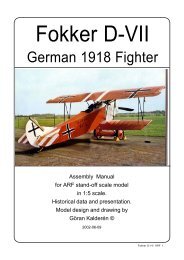
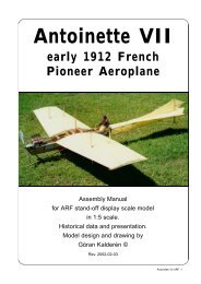
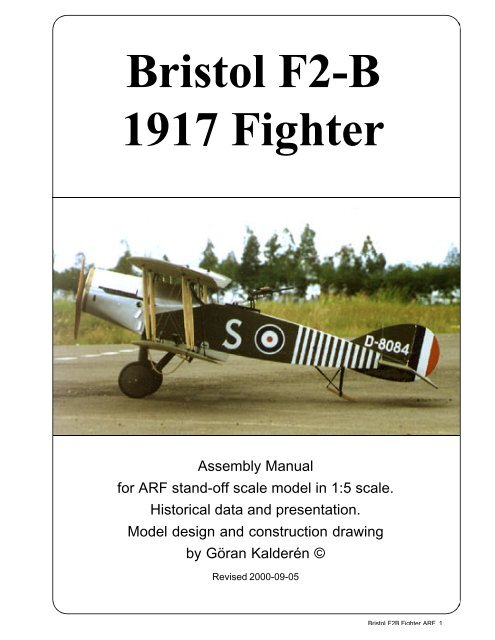
Bristol F2-B1917 FighterAssembly <strong>Manual</strong>for ARF stand-off scale model in 1:5 scale.Historical data and presentation.Model design and construction drawingby Göran Kalderén ©Revised 2000-09-05Bristol F2B Fighter ARF 1
Bristol Fighter F2BFor the British aircommand it becamein 1916 obvious that a replacement for the slowand vulnerable BE2 series of aircraft was badlyneeded. Bristol at this time had designed a 2seater airplane of girder box design. To overcomethe restricted forward view for the pilot theupper wing was placed only 1 foot above thefuselage. The pilot’s line of sight was obstructedonly by the mere airfoil section thus renderinggood visibility forward/upward and forward downward.The necessary distance between wingplanes was obtained by moving the lower wingdownward under the fuselage. The first productionaircraft were designated F2A but when putin service as a reconnaissance aircraft, the oldtactics were used and the plane became easyprey for the opponents.A revised model F2B fighter/reconnaissancewith improved 275 hp. Rolls-RoyceFalcon engine and fighter tactics applied, becamea tremendous success. This engine is liquidcooled and the radiator first deployed as sidemounted, soon was changed and located upfront giving the nose a characteristic outline.The armament was a Vickers .303 machine gunmounted under the hood and shooting synchronizedto fire through the propeller arc through around outlet in the upper part of the radiator. Forthe observer there was a Lewis machine gunmounted on a Scarff ring mount.As production increased during 1917 itbecame difficult for Roll-Royce to keep up withdemand and other engine alternatives were triedand employed.That this was a very successful aircrafttype shows in that more than 4700 aircraft wereproduced and that that production continued longafter the war had ended. The aircraft saw actionin many foreign countries and was used by theBritish in their overseas operations.As production of the F2B increased inspeed during the mid-Summer of 1917, additionalRoyal Flying Corps squadrons wereformed or re-equipped with the new Bristolfighter. The production F2B featured a reducedchord tail plane with longer span elevators. Thesewere later changed to use the elevators of theF2A with the tail plane of the F2B and this arrangementwas retained for all wartime F2Bs.The F2B benefited from the lessonslearned from the first combat use of the F2Avariants. When introduced in combat they wereflown in action using single seat fighter tactics,which immediately proved successful.The aircraft was armed with a single synchronized.303 Vickers machine gun with 963rounds of ammunition in the nose for the pilotand a .303 Lewis machine gun for the observerwith seven 97 round ammunition drums. Someaircraft were upgunned in the field with an additionalLewis gun mounted over the wing to augmentthe forward firepower and twin Lewis gunsin the rear cockpit mounted on a Scarff ring.The increased production rate at Bristol’sfor the F2B resulted in a shortage of enginessince Rolls-Royce was unable to keep pace withthe demand for Falcon engines As a result, alternativeengines were examined and tested;including the Siddeley Puma, Hispano-Suiza 200hp. Hispano-Suiza 300 hp and the 200 hp SunbeamArab. The Sunbeam Arab being finallychosen, although others continued to be testedsince the Arab equipped variants provedto be somewhat under-powered. The installationof the Arab engine altered the nose contoursand exhaust stack arrangement.Before the end of the First World War,the Bristol fighter was to see service in varioustheaters of war, including with No 139 in Italy andNo 67 (Australian) Squadron in the Middle EastNos. 33, 36, 39, 76 and 141 Squadrons usedBristol Fighters for home defense duties.F2Bs used by home defense units as night fighterswere modified in a number of ways. Somewere fitted with navigation lights on the lowerwing tips and rudders, Holt flare brackets beneatheach lower wing tip and illuminated gunsights. Other night fighters were fitted with additionalforward firing machine guns. One aircraftof No 39 Home Defense Squadron had two Lewisguns fitted over the wing in addition to its normalsingle Vickers gun and twin Lewis guns for theobserver.By November of 1918 over 5,500 Bristolfighters, mainly F2Bs, had been ordered and, ofthese, 3,101 had been taken into the RFC andRAF. Although the Armistice led to cancellationof some orders, the “Biff” as it was known towartime airmen, continued to be manufactureduntil September of 1919, with a total of 4,747being produced.Documentation is available in Bristol Fighterin Action, Aircraft # 137 by Squadron/signal PublicationsInc., 1115 Crowley Drive, Carrolltown,Texas 75011-5010, USA, ISBN-0-89747-301-9.Bristol Fighter by JM Bruce, Albatros ProductionsLtd., 10 Long view, Berkhamsted, Herfordshire,HP4 1BY, Great Britain. ISBN -0-948414-85-5.Bristol F2B Fighter ARF 2
Specification:Wingspan, 39' 3" (11,96 m.)Length, 25' 10" (7,87 m.)Heigth, 9' 9" (2,97 m.)Engine, 275 hp Rolls Royce Falcon IIIliquid cooled.Armament, 1 Vickers .303forward firing syncronizedmachine gun, 1 Lewis onScarf ring mount in rearcockpitSpeed, 113 mph., (182 kph)Service ceiling, 20,000 feetCrew, 2Bristol F2BFighter1917Bristol F2B Fighter ARF 3
Bristol F2B Fighter ARF 4
Bristol F2B Fighter and Canadian pilotsThe Canadian Air Force only ever held two ”Brisfits”or ”Bifs” on strength from 6 August, 1920 to 7 February,1922 as part of an Imperial Gift of 114 variedaircraft, however Canadian airmen flew the two-seatfighters in the service of the Royal Flying Corps aswell as the CAF during the First World War. CanadianAir Service pilot Lt. A.E. McKeever of No. 11Squadron soon began to be regarded as an aceamong Bristol Fighter exponents, and between himselfand his regular observer, Sgt. (later Lt.) L.F.Powell accounted for 28 aircraft from the time oftheir first victory on 26 June, 1917 and the end ofthe year. With the formation of No. 1 Squadron,Canadian Air Force, McKeever was appointed itscommanding officer and he adopted the BristolFighter as his personal aircraft. This machine laterwent with him when he returned to Canada after theArmistice and was later registered on the CanadianCivil Registry as G-CYBC.Bristol F2B Fighter ARF 5
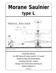
Our model depicts the Bristol F2b D8084, No.139Sqn RAF Villaverla <strong>Aerodrome</strong> in September 1918.Originally formed in March 1918 as ’Z’ Flight andattached to No.34 Sqn in Italy for long range reconnaissanceduties. By July 1918 a second flight hadarrived and the combined unit was known as No.139Sqn RAF. The original marking of two vertical whitebands soon gave way to four white and three blackbands and ultimately expanded to the 12 and 11depicted on D8084 as it is presently painted. Thisaircraft also carried a spanwise w/b/w stripe betweenthe upperwing. The pictures on this page are theBristol F2b Fighter of the Shuttlewort Collection inthe air above Old Warden <strong>Aerodrome</strong>, England.Below the same aircraft on the ground at Old Warden,Biggleswade.The paintwork shown is the postwar service, and prior to 1981 when the aircraft wasrendered the original camouflage and markings.Bristol F2B Fighter ARF 6
The Bristol F2B Fighter, that we have modeled, isthe aircraft that is kept in flying condition by theShuttleworth Collection in England. These picturesshow details of the aircraft as it looks today. Thefront cowling plates have been removed for serviceand reveal the powerful 12 cylinder Rolls Royce engineas well as the areas adjacent to the cockpit.The paint scheme was changed in 1981, when theaircraft was completely overhauled, and is now relevantto the period at the end of the war. The serialnumber has been placed on the fin and the aft sectionhas white stripes across the sides and uppersurface of the fuselage. The all over paint color is PC10(we use olive drab which is like sun bleached PC10)on all upper surfaces and natural linen off white on theunder surfaces. Above the large identification letter”S” is a instruction and warning not to fly without gunner/observeror equivalent weight in the rear cockpit.The model that we have depicted in this manual hassince been repainted and shows now the accuratescheme.All pictures on this pages, courtesy of ShuttleworthCollection, Old Warden <strong>Aerodrome</strong>,Biggleswade, Befordshire SG18 9EP, England.Bristol F2B Fighter ARF 7
The picture below shows also the spent cartridgechute and the rear part of the Vickers machine gun.The impressive Rolls Royce Falcon III 275 Hp 12cylinder liquid cooled V-engine.Bristol F2B Fighter ARF 8
The ModelWe have chosen the scale of 1:5 thatgives a model with the wingspan of almost 8 feet.This in turn is a rather large aircraft but the handlingin the air is very satisfactory.For transport to and from the flying field,both wing panel groups can be removed, riggedand complete, with only the disconnection of afew rigging wires 4 locking screws and the servoconnectors. All the settings and trims are preserved.As per prototype, the elevator can betrimmed for angle of incidence. All the riggingwires are functional and aid to the stability of theairplane. As additional feature, you can have afunctional exhaust manifold, connected to your4 stroke engine and displacing the exhaust in ascale manner.There is ample room for radio equipment,servos and extras that you would want to add.For ease of ground handling, the tailskid isstearable and coupled to the rudder bar withwires.The documentation refers to the aircraft,still today in flyable condition in the ShuttlewortCollection in England. The scale propeller deliveredwith the model is 2-bladed but a 4-bladedcan be supplied as extra item on request.The finished model is painted in 1918 liveryand further detailing can be made as perdocumentation.SpecificationWingspan 94" (239 cm)Length 62" (157 cm)Wing area 243 sq. inch 157(dm²)Weight 18 lb. (7900g)Wing Load (50 g/dm²)Engine .90 - 1.20 (15 - 20cc) 4-strokeCovering and finishThe model is covered and painted on theoutside from the factory. You should cover theengine compartment with fuel proof paint afteradjustments and installation of the engine. Weuse Solartex Antique and Olive drab coveringmaterial and matching Dutch Boy Enamel paints.Installation of engine.We recommend that you don’t overpowerthis model. It will fly happily with a 1.20 4-strokeengine. Our prototype was tried with a OS 1.204- stroke, which gave ample thrust. The enginemounts have been installed for this size ofengine. The access to the glow plug is difficultso we recommend an extension and you canplace the connector in the hole on the left side ofthe cowling.1. Adjust the width of the engine mounts ifnecessary, and drill the holes for the engine.Insert blind nuts to take the engine bolts.2. Install the 16 Oz tank on the right side inthe engine compartment. Connect the requiredsilicon tubing.3. Install the engine and connect the throttleservo.Installation of servos, tank, battery andreceiver.The aileron servos are installed in thewing root of the lower wing panels. A Y-cableleads up to the receiver. We recommend Dubro# 121 E/Z connector for these servos.The throttle servo is installed upright inthe servo tray.The elevator servo and the rudder servoare installed inverted in the tray.Battery pack and receiver are positionedin the upper tray.The switch is mounted on or under the instrumentpanel.To access the servo tray and receiver trayfor installation of the servos receiver and batterypack you will have to remove the upper and lowercenter wing sections. Beginning with the lowerwing section you will have to remove the landinggear. Release the cross bracing wires for thelanding gear and pull the legs straight out.Remove the 4 pcs 6-32 Allen screws and lift outthe lower wing section. Open and remove thehatch by removing the #2 sheet metal screws.The upper tray is accessible by removingTypical servo installationBristol F2B Fighter ARF 9
the upper center section (4 Allen 6-32 screws.Either one of the 2 aluminum panels can nowbe removed by unscrewing the sheet metalscrews. Note that different length of screwshave been used for the various locations. Therubber coaming can be removed and laterreplaced without using glue. The center sectionis held down by the windscreen , which can afterremoving one screw be swung to the sidereleasing the panel.1. Attach a clevis or ball link head to joystickand rudder bar in the appropriate holes. Youmay have to enlarge the holes to take the screwfrom the ball link (Dubro #189 set of 2).2. Install the servos for rudder and elevatorand connect the servo arms to the clevices orball links. Deflection for elevator is 20° up anddown and for rudder 30° right and left.3. Install and connect the throttle servo inthe fashion you prefer.4. Install the tank in the available space atthe right side of the engine compartment.5. Install the aileron servos in the wing root.The hatch cover is secured with 4 #2 sheet metalscrews. The aileron connecting rods attachesto the servo arm. Differential throw on the aileronis recommended Deflection of the aileronsshould be 25° up and 15°down.6. Install the switch on the instrument panel.7. Place the receiver and the battery packin the upper part of the tray, wrapped in foamrubber and secure with rubber bands.Assembly of the Bristol F2B FighterAll parts have been assembled at thefactory and only disassembled for transportation.Rudder and elevator wires are factoryadjusted but may need some tensioningadjustment after a while. Ailerons are adjustablewith the clevises to the connecting rod and tothe aileron horn.Assembly of the tail unit1. Secure the top and the bottom fins withthe brackets using #2 sheet metal screws. Therudder is permanently attached to the fins.2. Push the stabilizer with elevators on thebrass tubes in the fuselage. Connect the supportingwires with clips in their respectivepositions. See rigging sketch.3. Connect the elevator wires. Note thatthese wires are crossed.4. Connect the rudder wires. The wires forthe stearable tailskid are installed from thefactory.Assembly of wing panelsFlying- and drag-wires are 90 lb. breakingBristol F2B Fighter ARF 101.5 mm.30 mm.Complete "turnbuckle" assemblystrength, all other wires are 40 lb. breakingstrength.1. Push the lower wing halves into the holesin the lower wing center section and connect theservo leads to the Y-cable.2. Push the upper wing halves into theholes in the upper wing center section. Connectthe flying wires and the landing wires. Start withthe landing wires that are attached to the upperwing cabanes. Insert the inner pair of theinterplane struts (the forward is shorter).3. Now connect the flying wires to thisinterplane strut pair. Proceed with the next bayrepeating the procedure.4. When all struts have been installed, youcan connect the X-bracing for the interplanestruts.5. Last the drag wire are attached to thefuselage at the fitting behind the radiator.6. When both wings sets have beenassembled you will have to connect the aileronswith the interconnecting rod. This has clevisesin both ends to ease assembly. Check that thedistance is correct and adjust if necessary. Theailerons must be parallel on both wing halves.7. Lock the wing halves in position with thefour #2 sheet metal screws. The tabs are affixedto the wing sections.8. Check the dihedral. It should be 2.5" /6,5cm measured at each tip of the lover wings. Ifnecessary you can adjust the dihedral by tighteningand loosening the flying- and landing wires.You need not touch the interplane crossbracing.Disconnect the wires and start adjustment withTypical fashionof lacing bungeerubber cord.
The MQ version with full detailingOur prototype in flightCockpit details with optionalinstrument panel installedBristol F2B Fighter ARF 11
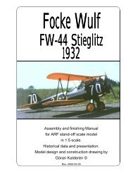
12814101111322 2233 1012 542 911635131346642714For clarity only one typical wire typeis indicated. The airplane has 4 front,4 rear flying wires, 4 front and 4 rearlanding wires.The 4 interplane strutt sections allhave X-bracing wires.2110 11These are the rigging wires:1. Rudder control wires2. Elevator control wires3. Front flying wires4. Rear flying wires.5. Front landing wires6. Rear landing wires.7. Landing gear cross bracing wiresthe inner bay section of each wing pair. Whencorect dihedral is obtained continue with theouter bay section. When completed, lock theclevices in position with the locking nuts. Thedragwires may also have to be adjusted whenyou have changed the dihedral.Should you need to replace a wire, use theattachment method indicated in the picture.When crimping the cerulet (sleeve) use a flatpliers, press firmly and don’t cut through the wire.8. Upper wing cabane cross bracing wires9. Lower wing cabane cross bracing wires10. Fin/stabilizer front support wires11. Fin/stabilizer rear support wires12. Drag wires.13. Interplane strut cross bracing wire14. Aileron connecting rodLanding gear1. Push the landing gear into the holes inthe fuselage. The rear landing gear struts passthrough the lower center wing section. Connectthe wire cross-bracing to hold the landing gearin place.2. Install the wheels on the shaft and securewith the stoppers.3. Lace rubber bands in the fashion shownin the sketch. This is a very efficient shockabsorber.Bristol F2B Fighter ARF 12
Adjustableleading edgesupportFixed screwsupportsFixed screwsupportsStabilizer fitsin hereAdjustment screwBalancingCheck the C/G and make adjustments ifnecessary. C/G should be within the range of 9cm - 12 cm (3.6" - 4.8") measured from theleading edge on the upper wing. The furtherforward you put the C/G the more "groovy" themodel behaves. This model has a relatively longnose moment and depending on what engineyou are using, wheight may be moved towardsthe rear of the plane. The original aircraft had tohave observer or balance weight in the rearcockpit or else it was nose heavy and dangerousto flyStabilizer trimIn the bottom of the fuselage at the positionof the stabilizer leading edge there are two 3 mmscrews. Initial setting should be 2° positiverelated to the thrust line (approx. 3 mm downfrom the top end position). By turning thesescrews, the leading edge of the stabilizer canbe moved up or down (clockwise = down). Tochange the setting, remove the clevises for thesupport wires at the leading edge of the stabilizer.Turn both adjustment screws the same numberof full turns. Turn the wire holder in the finsaccordingly, same number of full turns. If youmove the leading edge up, the upper and lowerwire attachment points are moved upwards. Clipthe clevises back into positions. If you find thatyour elevator trim requires a changed stabilizersetting, execute this trim and move your transmittertrim tab to neutral for the next flight.FlyingThe prototype was flown with a 1.20(20cc) OS FS 4-stroke engine. We used acustom built muffler allowing the exhaust to beemitted through the scale manifold.Flying characteristics are very forgivingand will fly happily on half trottle. During the initialtake off run you have to compensate for thetorque with right rudder but as the speed buildsup the rudder is returned to neutral. This modelshould fly of the ground and not be pulled. Onceairborne the aircraft is limited aerobatic like allbiplanes from WW I. Turns must be coordinatedrudder/elevator/aileron in prototype fashion.The landing approach can be rathersteep as per prototype but the flare out needsalmost full up elevator. Get the tail down tomaintain directional stability.If your enginge quits midair, remember toget the nose down to maintain flying speed. Thedrag from the wires and struts is considerable!Happy landings!Bristol F2B Fighter ARF 13
Cockpit interior including instrument panel is anadditional option.For adjustment of the stabilizer incidence it isrecommended to set the stabilizer approx 3mmfrom the upper end position. Adjust after intitialflight to suite your taste.The servo Y-leads from the receiver can berouted along the rear wing support to the centresection of the lower wing and then connected tothe servos in the wings. It will be necessary tomake a hole tin the root rib and in the rib of thecentre section for the servo leads.The wings can be removed as a "package"leaving only the wires to the fuselage unhookedand the servo connector disconnected.The tailskid is steerable and connected withwires to the rudder bar. This means a heavy loadon the rudder servo and should be observedwhen choosing the servo.Bristol F2B Fighter ARF 14
The engine installation is related to the type ofengine that you have chosen. We like to showhow we installed the OS 1.20 engine andincluding a "scale" type functional manifold.To ensure an unrestricted air inflow we removedthree panels of the screen above the propellershaft.We also installed deflection ducts made of 0,5mm alu sheet to force the air close to thecylindre.To prevent the air from stalling, we opened two1" holes in the fire wall into the open cockpit.This with the additional outlet created by thefunctional manifold gave a satisfactory air flow.We also installed a remote connector for theglow-plug as well as an on-board glow batterythat is engaged at idle.The tank has been installed diagonally in theengine com-partment to allow the use of astandard available typ.The throttle servo islocated in the servotray and has a straightlink to the throttle arm.The type of manifoldinstalled in ourprototype differs fromour standardmanufactured type inthat the inlet tube isconnected to the rearinterconnecting tubeand is of 10 - 15 mmdiam alternately.Custom made tospecific engines.Optional itemsFor this aircraft there are some additional itemsavailable separately (allow for 3 months delivery):ACC-401, Cockpit interior kit, consisting of instrumentpanel with all instruments, valves andswitches installed, pilots seat (vicker chair),throttle/mixture levers and rear section of Vickersmachine gun located in the hole in the instrumentpanel and visable in cockpit. Gunners seat and6 spare ammo magazines for the gunnerscockpit.ACC-248, 4-bladed scale propeller.ACC-251, Scale functional manifold and exhaustsystem for 1.20 4-cycle engine.ACC-850, Full body,1/5th scale British pilot / gunner.Bristol F2B Fighter ARF 15
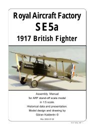
What is in the box:The ARF and RNF kits contains the parts shown in thepicture All the parts are covered and painted. All the riggingwires are supplied in the correct lengths and attachedto their fixed positions. Wings, interplanestruts, Fin/rudder and Stabilizer/elevator are separated at delivery.1110 99 1184121086215731. Fuselage with upper and lower wing cabanes2. Landing gear with wheel shaft3. Scale wheels4. Scale propeller5. Tail skid assy., mounted6. Fin with rudder7. Stabilizer with elevator (right and left halves)8. Upper wing panels9. Lower wing panels10. Interplane struts, (4 short front, 4 longer rear)11. Aileron interconnecting rods (2)12. Scarff ring mount with Lewis machine gun13. Wires, turnbuckles fitted at locations andhardware for assembly (not shown)K&WModelAirplanes Inc.Bristol F2B Fighter ARF 16The delivered model has a revised paintschemecorresponding to the present status of the original aircraftP.O.Box 1229, Cebu City Centrl. PostofficeCebu City 6000, PhilippinesVisiting address:3343 Gun-Ob, Kinalumsan,Lapu-Lapu City 6015, PHILIPPINESPhone +63 32-340 7147, Cellular +63 917-3200 985Telefax +63 32-340 7131, E-mail: kwmairpl@gsilink.com