Download PDF Manual - Macca's Vintage Aerodrome
Download PDF Manual - Macca's Vintage Aerodrome
Download PDF Manual - Macca's Vintage Aerodrome

Create successful ePaper yourself
Turn your PDF publications into a flip-book with our unique Google optimized e-Paper software.
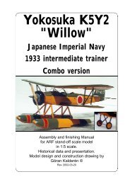
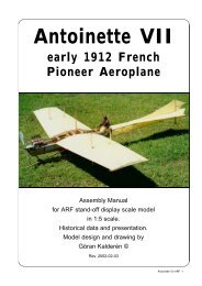
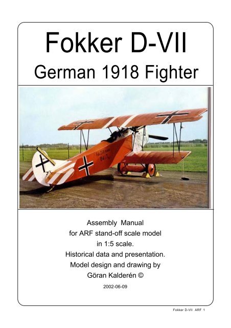
Fokker D-VIIGerman 1918 FighterAssembly <strong>Manual</strong>for ARF stand-off scale modelin 1:5 scale.Historical data and presentation.Model design and drawing byGöran Kalderén ©2002-06-09Fokker D-VII ARF 1
Fokker D.VIIThe Fokker D.VII was arguably the bestaircraft of the First World War ... it has beensaid it made a mediocre pilot good, and a goodpilot great. While this may be an exaggeration,the D.VII was the only German aircraftspecifically mentioned in the terms of thearmistice ending WW1, with all examples to beturned over to the Allies.The D.VII was built by three differentfactories - Fokker itself, Albatros and theAlbatros subsiduary of OAW. Each had its ownstyle of cowl and engine cooling louvres. Theselouvres were installed after a series of inflightfires in which aircraft spontaneously caught firewith disatrous results. This was thought to bedue to the temperature of the enginecompartment setting off the phosphorousammunition. Once these tribulations wereworked out, the D.VII went on to equip mostGerman Jastas.The Fokker D.VII was the work of Fokker's chiefdesigner, Reinhold Platz. Developed from thePlatz's V.11 prototype of 1917, which won theJanuary 1918 fighter competition at Adlershofby a handsome margin, the DVII entered largescaleproduction by Fokker and Albatrosfactories almost immediately afterwards andbegan to reach operational units in April. By theautumn of 1918, over forty Jastas were equippedwith the type and in the remaining months ofthe war the D.VII acquired a highly successfuloperational record. A sensitive but delightfulaeroplane to fly, the Fokker D.VII had andexcellent all round performance including firstclass manoeuverability at altitude. Its ability to"hang" on its prop while climbing was to spellthe end of many Allied machines with which itjoined in combat.The D.VII carried the standard armament of theperiod, two synchronised Spandau machineguns fixed over the top decking in front of thecockpit and firing between the propeller blades.At the time of the Armistice, Fokker haddelivered 412 D.VII's.Two kinds of power plant were installed in theD.VII's , the 160 h.p. Mercedes D.III or the 185h.p B.M.W. III, both six cylinder water cooled inlineengines. The D.VII's fuselage frame was bilt ofwelded steel tubing, and as a precaution againstpossible shortage of this commodity Albatroscompleted one experimental D.VII with an all woodfuselage. The precaution, however, provedunnecessary. A two seat develoopment, the C.IOwas built in small numbers but did not becomeoperational.Brief Technical DetailsEngine: One 185h.p. B.M.W. IIIa inline sixcylinder water cooledWing Span: 29ft 2.33 inchesFuselage Length 22ft 9.75 inchesHeight: 9ft 0.25 inchesWeight Empty: 1,513 lb Loaded 1,993 lbMax Speed: 124 m.p.h. at sea levelCeiling: 22,900 ftDuration: 1hr 30minArmanent: Two fixed foward firing Spandaumachine guns.Our ModelThe K&W DVII is built in 1/5 scale, rendering amodel size that is easy to fly, but also relativelyeasy to transport. Both the upper and the lowerwing panels can be removed for transport whichgives very limited requirement for transportation.Rudder is controlled by pull-pull cablesfrom the rudder bar and the elevator by pull-pullcables connected to the control column. The DVIIhas upper wing ailerons that are connected to aservo in the wing.The prototype was equipped with a Saito.90 4 cycle engine that gives ample power for thisfighter. With this engine the airplane is capableof some advanced manoeuvers which you can demandfrom a WW1 biplane fighter. The momentarms are short and the rudders sensitive, so fly ifyou can, with a dual rate transmitter.The finished model is available in two standardlivererys, the Lozenge pattern reflected inthe original at the RAF museum in Hendon, andthe pattern that is reflected in the original in theDeutsch museum. Other patterns are available onspecial order.Fokker D-VII ARF 3
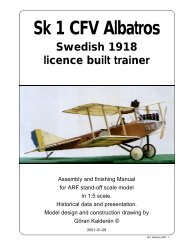
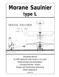
SpecificationWingspan: 29'-2.33"Length: 22'-9.75"Engine: Mercedes 160 H.P. liquid cooled185 H.P. B.M.W inline sixArmament: 2 Spandau Machine gunsFokker D-VII ARF 4
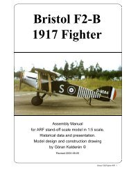
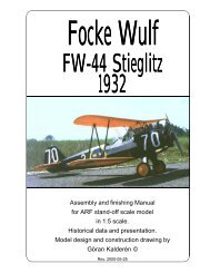
The K&W Fokker DVII1/5 Scale ModelLozenge Pattern aftermodel in the HendonMuseum.Fokker D-VII ARF 5
Fokker D-VII ARF 6
Fokker D-VII ARF 7
Installation of servos, tank, battery and receiver.The aileron servo is installed in the lowerpart of the upper right wing. The ailerons areoperated by rods that are coupled to the aileronsvia bell cranks in the outer wing panels.The rods are preinstalled in the wings. The rudderand elevator servos are installed in the trayprovided and connected to the rudder bar andcontrol column via rods and ball links. The trottleservo should be installed in the engine bay.Fashion a mount out of scrap wood and installas desired. The tank is positioned in the enginebay below the dummy engine. Battery pack andreceiver are positioned in the upper part of thetray. The switch can be mounted on the servotray with extension rod or on the instrumentpanel.1. Attach a ball link head to joystickandrudder bar in the appropriate holes. You mayhave to enlarge the holes to take the screw fromthe ball link (Dubro #189 set of 2).2. Install the servos for rudder and elevatorand temporarily connect the servo arrnsto the ball links. Neutral position for the elevatoris in line with the stabilizer. Deflection for elevatoris 20° up and down and for rudder 30° rightand left..3. Install and connect the throttle servoin the fashion you prefer.4. Install the tank in the available spacein the engine bay.5. Install the aileron servo in the servobay ( see photo) that is in the upper right wing.The ailerons are operated by push rods. Therods are preinstalled at the factory. When youconnect the two haves of the upper wing together,thread the push rod from the left wingthrough the appropiate hole. Fasten the two pushrods to the servo actuator arm. There are a numberof ways to accomplish this task, we built anadaptor plate for the servo arm that held therods with servo connectors.6. Install the radio switch on the dash board.7. Place the receiver and the battery packin the upper part of the tray wrapped in foam rubberand secure with rubber bands.Assembly of the Fokker DVIIAll parts have been assembled at the factoryand only disassembled for transportation.Rudder and Elevator wires are factory adjustedbut may need some tensioning adjustmentafter a while. We recommend using a push rodand ball link to connect the elevator and rudderservos to the control column and rudder barrespecively.Assembly of the tail unit1. Fit the horizontal stabilizer to the fuselagewith the three nylon screws provided.2. Fit the vertical stabilizer to the horizonalstabilizer, aligning the lower hinge to the slot providedin the fuselage. Then attach the vertical stabilizerto the tail plane using the two brackets providedalong with a screw in the forward part of thestabilizer. (see photos). Finally, connect the presetsupport wires between the stabilizers.3. Connect up the pull-pull cables.4. Check the throw of rudder (30° right andleft) and elevator (20° up and down). Rudder isactuated by the rudder bar and the elevator bythe joystick.Tail Assembly photosHorizontal stabilizer ismounted using threenylon screwsPreset Pull-Pull cablesTail mounting bracketAssembled Tail group.Fokker D-VII ARF 9
Assembly of wing panels1. Thread a length of servo wire throughthe tube on the right side rear wing support2. Push the lower wing halves onto thesupport tubes in the fuselage.3. Join the upper wing halves using thetubes provided. Insure the aileron push rod isaligned to the hole in the right wing. Secure thetwo halves (with the provided straps) across thewing center line. Connect up the servo to the aileronpush rods.3. Install the top plane and the interplanestruts. Note the rear strut from the fuselage to theupper wing is adjustable in length, the purposebeing to adjust the wing incidence. Also, theinterplane struts are adjustable in a like manner.The documentation indicates the upper and lowerwings were set a zero degrees incidence, the tailplane is set at a positive 3.5 degrees.4. The Aileron throw should be appx 20degrees up and down.Landing gearInstall the wheels on the shaft and securewith the stoppers. Lace rubber bands in the fashionshown in the sketch.This is a very efficient shock absorber.Lacing of bungee rubberfor the wheel shaftBalancingThe C/G (center of gravity) or balancing pointshould be set at 12.3 cm (appx 5”) measuredfrom the center of the leading edge on the upperwing. Make adjustments by adding wheight if necessary.If you desire a more groovy and stableflight performance you may move the C/G as muchas 1" forward.FlyingLet the engine swing a 14"x6" propeller if possible.This gives better thrust outside the large frontradiator and reduces sound to a more realisticlevel.Flying characteristic is that of a biplane fromthe WW-I period and it will fly happily on 3/4throttle. Ground handling on a hard surface demandsa gentle hand but on grass surface, thetailskid provides enough directional stability. Duringthe initial take off run first keep full up elevatorto keep the tail down. As the speed builds up, letgo gradually of the up elevator and the tail comesup. You have to compensate for the torque withright rudder but as the speed builds up the rudderis returned to neutral. This model should fly of theground and not be pulled. Like many other planesfrom this period this type has a positive incidenceon the stabilizer that in theory should offset theclimbing tendency of the high lift wing profile. Onceairborn the aircraft is limited aerobatic like all biplanesfrom WW 1. Remember that all turns aremade using rudder and elevator and compensatedwith aileron!The landing approach can be rather steep asper prototype but the flare out needs almost fullup elevator. Once on the ground keep the tail downto maintain directional stability. In case you haveto make a dead stick landing, keep the nose downand the speed up. The struts produce a lot of drag!It is always better to do a good landing in a badplace than vice versa...Happy landingslFokker D-VII ARF 10
The K&W Fokker DVII in the bonesThe K&W Fokker DVII finished inLozenge Pattern.Fokker D-VII ARF 11
The K&W Fokker DVII standing on itsnose.Fokker D-VII ARF 12
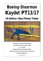
What is in the box:The ARF kit contains the parts shown in the picture.All the parts are covered and painted. All the rigging12wires are supplied in the correct lengths and needonly to be clipped to their positions.91036417521181. Fuselage with wing cabane,landing gear and tail skid.2. Scale wheels3. Engine cowl (4 pcs)4. Dummy engine with mount5. Scale propeller6. Radiator7. Fin / rudder8. Stabilizer / elevator9. Upper wing panels10. Lower wing panels11. Interplane struts12. Assembly <strong>Manual</strong>K&WModelAirplanes Inc.P.O.Box 1229, Cebu City Centrl. PostofficeCebu City 6000, PhilippinesVisiting address:3343 Gun-Ob, Kinalumsan,Lapu-Lapu City 6015, PHILIPPINESPhone +63 32-340 0772, Cellular +63 917-3200 985Telefax +63 32-340 7131, E-mail: kwmairpl@gsilink.comWebsite http://www.kwmairpl.com.phFokker D-VII ARF 13