How to build a radio-controlled Stearman PT-17
How to build a radio-controlled Stearman PT-17
How to build a radio-controlled Stearman PT-17

You also want an ePaper? Increase the reach of your titles
YUMPU automatically turns print PDFs into web optimized ePapers that Google loves.
<strong>Stearman</strong> Kaydet <strong>PT</strong><strong>17</strong> ARF 3
<strong>Stearman</strong> Kaydet <strong>PT</strong><strong>17</strong> ARF 4
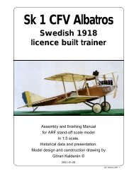
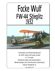
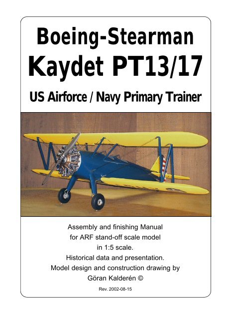
<strong>Stearman</strong> <strong>PT</strong>-<strong>17</strong> KaydetLength: 25' 7.62 MHeight: 9' 2" 2.79 MWingspan: 32' 2" 9.80 M<strong>Stearman</strong> Kaydet <strong>PT</strong><strong>17</strong> ARF 6Wingarea: 297.00 Sq Ft 27.59 Sq MEmpty Weight: 1936.00 lbs 878.00 KgGross Weight: 27<strong>17</strong>.00 lbs 1232.00 KgPowerplant: Continental R-670-5, 220 hp
<strong>Stearman</strong> Kaydet <strong>PT</strong><strong>17</strong> ARF 9
stabilizer <strong>to</strong> <strong>to</strong>p of fin).6. Secure and tighten all screws and nuts.Check the action of eleva<strong>to</strong>r and rudder. Theeleva<strong>to</strong>r is actuated with the joy-stick and therudder with the rudder bar.Assembly of wing panels1. Push the lower wing halves in<strong>to</strong> the holesin the fuselage.2. Attach the upper wing center section usingthe 4 Allen 6-32 screws supplied (note that thefront screws are longer and the rear screwsshorter). Attach ball links or clevices <strong>to</strong> the aileronpush rods. Connect the aileron push rods <strong>to</strong> theservo in the fuselage.. Check the movement ofthe ailerons. 20° up and 15° down throw.3. Install the interplane struts. Connect theflying wires and the landing wires. Attach the flyingwires in place. Attach the landing wires inplace. Adjust if necessary, the rear lowerincidence adjustment screw and the fasten thisassembly <strong>to</strong> the bracket on the lower wing using2 mm screw and locknut.Should you need <strong>to</strong> replace a wire, use theattachment method indicated in the picture. Whencrimping the cerulet (sleeve) use a flat plier, pressfirmly and don't cut through the wire.Landing gearInstall the wheel shafts and secure with theAllen socket locking screws. The landing gear iscompletely built up with oleo spring action and is<strong>Stearman</strong> Kaydet <strong>PT</strong><strong>17</strong> ARF 10an integrated part of the fuselage. The wheelsare secured with locking rings and the wheel capsare pushed on<strong>to</strong> the wheel hubs.BalancingThe center of gravity / balancing point should beapprox. 15 cm (6") measured from the leadingedge on the upper wing. Make adjustments ifnecessary.FlyingThe pro<strong>to</strong>type was flown with a OS 1.204-stroke FS which provides ample thrust. Let theengine swing a 18x6 propeller if possible. Thisgives better thrust outside the big dummy engineand reduces sound <strong>to</strong> a more realistic level.Flying characteristics are very forgivingand will fly hapily on half trottle. Set the eleva<strong>to</strong>rat zero angle for the first flight but be prepared<strong>to</strong> give down eleva<strong>to</strong>r if the model climbs out <strong>to</strong>osteep. During the initial take off run you have <strong>to</strong>compensate for the <strong>to</strong>rque with right rudder butas the speed <strong>build</strong>s up the rudder is returned <strong>to</strong>neutrual. This model should fly of the ground andnot be pulled.The landing approach can be rathersteep as per pro<strong>to</strong>type but the flare out needsalmost full up eleva<strong>to</strong>r. Maintain directionalheading and remember, the aircraft has astearable tailwheel.Happy landings!
The OS 1.2 engine blends nicely with thedummy engineThe tailwheel iscoupled <strong>to</strong> therudder bar and has50% throw of therudderRudder and eleva<strong>to</strong>r servos in the flooringof front cockpitPush rods from the servos attach <strong>to</strong> therudder bar and the control column.Aileron servo in theflooring of rearcockpit. Note theservo arm with 2attachment pointfor the clevices ofthe aileron pushrods.<strong>Stearman</strong> Kaydet <strong>PT</strong><strong>17</strong> ARF 11
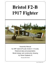
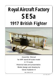
What is in the box:The ARF kit contains the parts shown in the picture.All the parts are covered and painted. All the riggingwires are supplied in the correct lengths and needonly <strong>to</strong> be clipped <strong>to</strong> their positions.9134115<strong>17</strong>3210861. Fuselage with wing cabane2. Landing gear3. Scale wheels4. Dummy engine with mount5. Scale propeller6. Tail wheel assy (stearable).7. Fin with tailfairing / rudder8. Stabilizer / eleva<strong>to</strong>r9. Upper wing panels10. Lower wing panels11. Interplane struts12. Wires, turnbuckles and hardware for assembly(not shown)13. Assembly manual with scaledocumentationK&WModelAirplanes Inc.<strong>Stearman</strong> Kaydet <strong>PT</strong><strong>17</strong> ARF 12P.O.Box 1229, Cebu City Centrl. Pos<strong>to</strong>fficeCebu City 6000, PhilippinesVisiting address:3343 Gun-Ob, Kinalumsan,Lapu-Lapu City 6015, PHILIPPINESPhone +63 32-340 0772, Cellular +63 9<strong>17</strong>-3200 985Telefax +63 32-340 7131, E-mail: kwmairpl@gsilink.comWebsite http://www.kwmairpl.com.ph