Download PDF Manual - Macca's Vintage Aerodrome
Download PDF Manual - Macca's Vintage Aerodrome
Download PDF Manual - Macca's Vintage Aerodrome
- No tags were found...

Create successful ePaper yourself
Turn your PDF publications into a flip-book with our unique Google optimized e-Paper software.
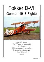
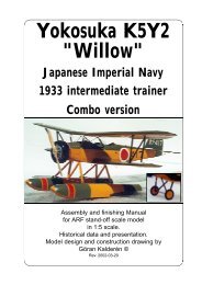
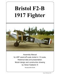
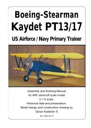
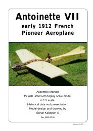
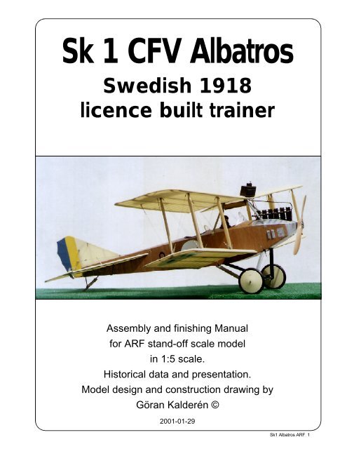
Sk 1 CFV AlbatrosSwedish 1918licence built trainerAssembly and finishing <strong>Manual</strong>for ARF stand-off scale modelin 1:5 scale.Historical data and presentation.Model design and construction drawing byGöran Kalderén ©2001-01-29Sk1 Albatros ARF 1
Sk1 CFV Albatros 120Produced early in 1914, the Albatros B-II wasa development of the highly successful pre-war twoseaterdesigned by Ernst Heinkel. For its day it wasa powerful aeroplane and this fact, allied to its wellproportioned rugged construction, admirably suitedit for its General Duties classification.In July 1914 a sales representative/companypilot toured Northern Europe and after a visit inCopenhagen, Denmark the tour aimed forStockholm, Sweden. Upon landing on a military trainingfield in the northern part of Stockholm, disasterstruck and the aircraft overturned, breaking the propellerand damaging the fin and rudder. Replacementparts were ordered from Berlin but when theyarrived in Sweden, the propeller did not fit. A localairplane manufacturer helped to make the necessaryadjustments but in the meantime the war brokeout in Germany and the crew was telegraphicallyordered to return to Berlin, leaving the aircraft behind.Although quite orthodox in appearance theAlbatros BII did have one or two unique features.The wings, however, were a fairly normal two-baystructure built up on two wooden main spars, theforward spar being in very close proximity to the leading-edgeand the rear spar at midchord. This resultedin an extremely flexible trailing-edge which addedconsiderably to lateral stability. Ribs were of spruceply and the whole wing structure fabric covered; thetrailing-edge was of wire which resulted in the distinctivescalloped appearance associated with somany German aircraft. Ailerons were of steel tubeconstruction, of inverse taper, and operated viacables through the lower wing. The centre-sectioncut-out was of vee-shape with slightly curved sidesand extended forward to the rear spar. Bothinterplane, and centre-section trestle struts, were ofstreamlined steel tube and braced with strandedcable. Stagger and sweep were both nil, dihedral wasin the nature of 4 deg. and incidence 4.8 deg.One of the unique features of this machinewas the plywood covered fuselage. Built on a foundationof six longerons (two ash and four spruce)and sturdy ply formers, no internal wire bracing wasneeded and an extremely rugged structure resulted.Apart from a slightly rounded decking aft of the rearcockpit the fuselage was quite ‘slab sided’ and taperedto a vertical knife-edge at the rear The extremelyangular tail surfaces were of considerablearea and made for great stability. All the fixed surfaceswere of triangular profile while the outline ofthe control surfaces was approximately trapezoidal.The fabric covers empennage was completely constructedof steel tube and of ‘flat plate’ section. Pilot’scontrols consisted of normal rudder-bar and a wheeltype control column for aileron and elevator control.Throttle was conveniently situated to the left handand in the event of any failure in the linkage to theengine, the motor automatically went to full throttleand did not stop as was the arrangement on Alliedtypes. Instruments fitted included revolution counter,altimeter, fuel pressure gauges, fuel pressure pump,magneto switches, temperature gauge, etc. Air speedindicators were not usually fitted in the cockpits ofany German aircraft; but when carried they were ofthe anemometer type, and clamped to a strut easilyvisible to the pilot. A compass was usually slung inthe apex of the centre-section trestle or in the lowerwing root.There was nothing exceptional about the undercarriagewhich was of normal steel tube vee-type,the axle being sprung with elastic cord. The ash tailskid was likewise sprung with this cord.The radiator was mounted on the leading edge ofthe top wing and it had louvres adjustable from thecockpit, to regulate the amount of cooling air needed.The original aircraft was copied at to a certainextent, improved. It was manufactured by severalaircraft manufacturer in Sweden including themilitary factory in Linköping. Several of these airplanesserved on and when the Swedish Airforcewas formed in 1926, they were transferred and renamedSk1 and Ö1 depending on the powerplantinstalled.Sk1 Albatros ARF 2Sk1 Albatros 120 in the Swedish Airforce Museum
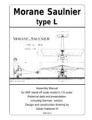
Sk 1, a licence built Albatros B II in the SwedishAirforce Museum in Linköping, SwedenSk1 Albatros ARF 3
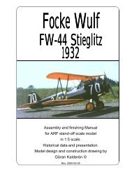
Above, Albatros in early markings prior to creation of the Swedish Airforce. Below, after 1926Sk1 Albatros ARF 4
Sk 1 AlbatrosWingspan upper13.08 mWingspan lower11.28 mChord upper and lower 1.80 mDihedral upper and lower 2°Length7.80 mHeight2.96 mEmpty weight840 kgLoaded weight1350 kgMaximum sspeed132 mphEngine120 hp BenzCrew 2Sk1 Albatros ARF 5
The ModelWe have chosen the scale of 1:5 rendering amodel size that i easy to fly but also relatively easyto transport. Both the upper and the lower wing panelscan be removed for transportation which gives verylimited requirement for transportation size. The momentarms are short and the rudders sensitive, sofly if you can, with a dual rate transmitter.The finished model is painted in 1915 liveryand further detailing can be made as perdocumentation.Specifications:Wingspan 102" (259 cm),Length 63.8" (162 cm),Wing area 92.5 sq inch (88 dm²)Weight 16 lb. 1 oz (7200 g)Wing Load(51 g/dm²)Engine 4-cycle 1.20(20 cc)Covering and finishThe model is covered and painted from thefactory. When you have made changes in the enginemount and wall and adapted the dummy engine tofit in line with the engine, you will have to cover theopen areas with fuel proof paint.Installation of engineWe suggest that you install the engine with 2°right thrust and 2° downthrust.1. Drill the holes for the engine and install blindnuts from the bottom.2. Drill the holes from the tank to the carburator,pressure tap and the filling cap.3. Install the engine and connect the throttleservo.4. Make cut outs in the dummy engine so thatthis will fit in front of your engine. You may have toremove 1 complete cylinder to allow for the coolingair to pass the engine head. This "surgery" isexecuted by removing a little at the time andchecking. When you are satisfied with the fit andopenings, screw the dummy engine onto the enginebulkhead using 3 #2 sheet metal screws and washers.Installation of servos, tank, battery and receiver.The aileron servos (2) are installed in the lowerpart of the servo vertical bulkhead in the fuselagebottom. Access through hatch between landing gearstruts.The elevator servo and the rudder servo areinstalled in the servo tray. The tank is positionedbelow the tray with the dummy engine.The trottle servo is positioned on the left wallin the engine compartment.Battery pack and receiver are positioned inthe upper left part of the engine compartment with ahatch covering the assembly.The switch can be mounted on the servo traywith extension rod or on the instrument panel.1. Attach a ball link head to joystick and rudderbar in the appropriate holes. You may have to enlargethe holes to take the screw from the ball link (Dubro#189 set of 2).2. Install the servos for rudder and elevator andtemporarily connect the servo arms to the ball links.Deflection for elevator is 20° up and down and forrudder 30° right and left..3. Install and connect the throttle servo in thefashion you prefer.4. Install the tank in the available space at theright side under the tray with the dummy engine.5. Install the aileron servo in the bulkhead. Theaileron wires are connected to the servo arms andthe idle wires are connected to each other. arm.Deflection of the ailerons should be 20° up and down.6. Install the radio switch on the dash board.7. Place the receiver and the battery pack inthe upper part of the tray, wrapped in foam rubberand secure with rubber bands.Assembly of the Sk1 Albatros 120All parts have been assembled at the factoryand only disassembled for transportation.Rudder and elevator wires are factory adjustedbut may need some tensioning adjustment after awhile. The aileron wires have a long way to traveland need adjustment after short use.Assembly of the tail unit1. Insert the fin post in the slot in the rear of thefuselage. Insert the front part of the fin in the bracketand secure with 2mm screw and nut. Secure thevertical fin post in the fuselage with 2 mm screw andnut.2. Push the two stabilizor halves on to the rodsin the fuselage.3. Attach the lower 4 stabilizer support strutswith #2 sheet metal screws supplied.4. Attach the upper 2 stabilizer/fin support strutswith #2 sheet metal screws in the stabilizer and 2mmscrew and nut in the fin.5. Connect the elevator cables and the ruddercables and check for movement.Assembly of wing panels1. Push the lower wing halves into the holes inthe fuselage.Turnbuckle for riggingSk1 Albatros ARF 6
84653217 65436379These are the rigging wires:1. Rudder control wires.2. Elevator control wires.3. Front flying wires.4. Rear flying wires.2. Attach the upper wing sections by pushingthe rods through the holes in the wing cabane. Thershould be approx 1/8" space on both sides of thecabane center piece.3. Install the interplane struts. Connect the strutcross bracing by clipping the kwick links in place.4. Connect the landing wires, the flying wiresand the drag wires.5. Connect the aileron wires to the aileron horns.The wires lead via the pulleys in the lower wing tothe fuselage and the front pair connect to the servoarms. The rear pair are connected to each other,thereby formimg a closed loop. Check the throw andthat there are no bindings.Servo armAttach centersection with2pcs 2 mmscrews, onefrom eachsideCut fromnylon hornMove piece upfor less throw.Reverse piecefor more throw.throw.Kwik-link toaileron wire.Drill 3 holes1,5 mm diamShould you need to replace a wire, use theattachment method indicated in the picture. Whencrimping the cerulet (sleeve) use a flat plier, pressfirmly and don't cut through the wire.Landing gear1. Install the wheels on the shaft and securewith the stoppers.Lace rubber bands in the fashion shown in thesketch. This is a very eficient shock absorber.5. Front landing wires6. Rear landing wires.7. Interplane strut bracing wires.8. Aileron control wires.9. Landing gear bracing wires.BalancingThe center of gravity / balancing point should beapprox. 25% of the cord of the upper wing. 9 cm(3.7") measured from the leading edge on the upperwing. Make adjustments if necessary.FlyingThe prototype was flown with a Y.S. 1.20(20cc) 4-cycle engine. There is ample power for thisslow flying airplane. We also installed a functionalexhaust muffler (rhinohorn) throught which theemitted smoke is belching out up over the top of theupper wing.Flying characteristics are very forgiving andwill fly hapily on half trottle. Set the elevator at zeroangle for the first flight but be prepared to give downelevator if the model climbs out too steep. Duringthe initial take off run you have to compensate forthe torque with right rudder but as the speed buildsup the rudder is returned to neutrual. This modelshould fly of the ground and not be pulled. Onceairborn the aircraft is limited aerobatic like all biplanesfrom WW I. Remember to initiate your turns withrudder and then as the as the airplane swings aroundcompensate with aileron and elevator. Coordinatedrudder, elevator and aileron in turns is the onlypossible way to fly these biplanes.The landing approach can be rather steepas per prototype but the flare out needs almost fullup elevator. Get the tail down to maintain directionalstability.Happy landings!Sk1 Albatros ARF 7
Installation of tank and servos is explained in detail above and belowSk1 Albatros ARF 8
Shown above is a typical engine installation. The YS 1.20 used in our prototype gave adequatepower and renderd very scale like flight characteristics. The necessary cut out in the dummyengine is selfexplanatory. Remember to cover the open surfaces with fuel protective paint.The sketches below show a typical interior of the cockpit. Also note the handle on the port (right)side for actuating the brake.Sk1 Albatros ARF 9
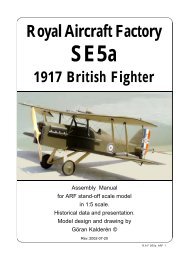
What is in the box:The ARF kit contains the parts shown in the picture.All the parts are covered and painted. All the riggingwires are supplied in the correct lengths and needonly to be clipped to their positions.131010814 4569711231. Fuselage with wing cabane2. Landing gear3. Scale wheels4. Engine cowl5. Dummy engine with mount6. Scale propeller7. Tail skid assy.8. Fin with rudder9. Stabilizer with elevator10. Upper wing panels11. Lower wing panels12. Wires, turnbuckles and hardware for assembly(not shown)13. Assembly manual with scaledocumentationK&WModelAirplanes Inc.P.O.Box 1229, Cebu City Centrl. PostofficeCebu City 6000, PhilippinesVisiting address:3343 Gun-Ob, Kinalumsan,Lapu-Lapu City 6015, PHILIPPINESPhone +63 32-340 7147, Cellular +63 917-3200 985Telefax +63 32-340 7131, E-mail: kwmairpl@gsilink.comSk1 Albatros ARF 10