Download PDF Manual - Macca's Vintage Aerodrome
Download PDF Manual - Macca's Vintage Aerodrome
Download PDF Manual - Macca's Vintage Aerodrome
- No tags were found...

Create successful ePaper yourself
Turn your PDF publications into a flip-book with our unique Google optimized e-Paper software.
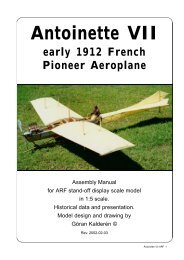
The ModelWe have chosen the scale of 1:5 rendering amodel size that i easy to fly but also relatively easyto transport. Both the upper and the lower wing panelscan be removed for transportation which gives verylimited requirement for transportation size. The momentarms are short and the rudders sensitive, sofly if you can, with a dual rate transmitter.The finished model is painted in 1915 liveryand further detailing can be made as perdocumentation.Specifications:Wingspan 102" (259 cm),Length 63.8" (162 cm),Wing area 92.5 sq inch (88 dm²)Weight 16 lb. 1 oz (7200 g)Wing Load(51 g/dm²)Engine 4-cycle 1.20(20 cc)Covering and finishThe model is covered and painted from thefactory. When you have made changes in the enginemount and wall and adapted the dummy engine tofit in line with the engine, you will have to cover theopen areas with fuel proof paint.Installation of engineWe suggest that you install the engine with 2°right thrust and 2° downthrust.1. Drill the holes for the engine and install blindnuts from the bottom.2. Drill the holes from the tank to the carburator,pressure tap and the filling cap.3. Install the engine and connect the throttleservo.4. Make cut outs in the dummy engine so thatthis will fit in front of your engine. You may have toremove 1 complete cylinder to allow for the coolingair to pass the engine head. This "surgery" isexecuted by removing a little at the time andchecking. When you are satisfied with the fit andopenings, screw the dummy engine onto the enginebulkhead using 3 #2 sheet metal screws and washers.Installation of servos, tank, battery and receiver.The aileron servos (2) are installed in the lowerpart of the servo vertical bulkhead in the fuselagebottom. Access through hatch between landing gearstruts.The elevator servo and the rudder servo areinstalled in the servo tray. The tank is positionedbelow the tray with the dummy engine.The trottle servo is positioned on the left wallin the engine compartment.Battery pack and receiver are positioned inthe upper left part of the engine compartment with ahatch covering the assembly.The switch can be mounted on the servo traywith extension rod or on the instrument panel.1. Attach a ball link head to joystick and rudderbar in the appropriate holes. You may have to enlargethe holes to take the screw from the ball link (Dubro#189 set of 2).2. Install the servos for rudder and elevator andtemporarily connect the servo arms to the ball links.Deflection for elevator is 20° up and down and forrudder 30° right and left..3. Install and connect the throttle servo in thefashion you prefer.4. Install the tank in the available space at theright side under the tray with the dummy engine.5. Install the aileron servo in the bulkhead. Theaileron wires are connected to the servo arms andthe idle wires are connected to each other. arm.Deflection of the ailerons should be 20° up and down.6. Install the radio switch on the dash board.7. Place the receiver and the battery pack inthe upper part of the tray, wrapped in foam rubberand secure with rubber bands.Assembly of the Sk1 Albatros 120All parts have been assembled at the factoryand only disassembled for transportation.Rudder and elevator wires are factory adjustedbut may need some tensioning adjustment after awhile. The aileron wires have a long way to traveland need adjustment after short use.Assembly of the tail unit1. Insert the fin post in the slot in the rear of thefuselage. Insert the front part of the fin in the bracketand secure with 2mm screw and nut. Secure thevertical fin post in the fuselage with 2 mm screw andnut.2. Push the two stabilizor halves on to the rodsin the fuselage.3. Attach the lower 4 stabilizer support strutswith #2 sheet metal screws supplied.4. Attach the upper 2 stabilizer/fin support strutswith #2 sheet metal screws in the stabilizer and 2mmscrew and nut in the fin.5. Connect the elevator cables and the ruddercables and check for movement.Assembly of wing panels1. Push the lower wing halves into the holes inthe fuselage.Turnbuckle for riggingSk1 Albatros ARF 6