Download PDF Manual - Macca's Vintage Aerodrome
Download PDF Manual - Macca's Vintage Aerodrome
Download PDF Manual - Macca's Vintage Aerodrome
- No tags were found...

You also want an ePaper? Increase the reach of your titles
YUMPU automatically turns print PDFs into web optimized ePapers that Google loves.
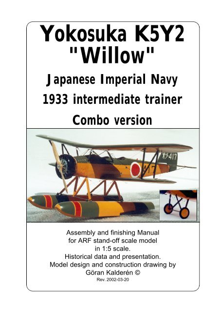
Yokosuka K5Y2"Willow"Japanese Imperial Navy1933 intermediate trainerCombo versionAssembly and finishing <strong>Manual</strong>for ARF stand-off scale modelin 1:5 scale.Historical data and presentation.Model design and construction drawing byGöran Kalderén ©Rev. 2002-03-20
Yokosuka K5Y2 " Willow" ARF 5
Yokosuka K5Y2 " Willow" ARF 7
Left side view of aircraftTop view of aircraftSpecification 5KY2Wingspan:10,985 mLength:8,050 mHeigth:3,200 mWing area upper: 16,2 m²Wing area lower: 11 ,5 m²Wing area total: 27,7 m²Horizontal tailplane area: 1,42 m²Elevator deflection up: 30°Elevator deflection down: 20°Stabilizer trim: +5° -2°Aileron deflection: 30°Powerplant: Hitachi Amakaze 11300hp, 9 cylinder radial aircooledPropeller:2 bladed woodMax.Speed:115 kt at sea levelService ceiling:5700m, 19000feetRange:550 naut. milesInstrument panelfront cockpitUpper wing airfoilLower wing airfoilInstrument panelrear cockpitFront view of aircraftYokosuka K5Y2 " Willow" ARF 8
The ModelWe have chosen the scale of 1:5 rendering amodel size that is easy to fly but also relatively easyto transport. Both the upper and the lower wing panelscan be removed for transportation which gives verylimited requirement for transportation size. Werecommend a 1.20 4-stroke or a .90 2-stroke engine.The 4 stroke engine fits in upright position and blendsvery nicely with the dummy engine cylindres. Thisaircraft was designed for limited aerobatics of the timeand can be flown through simple manouevres. At thesame time it was a trainer and the low speed behaviouris rather docile and allows for the pilot to think...This model has all control surfaces connectedin scale fashion. The ailerons are actuated viaconnecting rods to bellcranks in the lower wings, whichi turn are connected with wires via pulleys to theailerons in the lower wings. The upper ailerons areconnected with dual wires from the lower ailerons inscale fashion. The elevator is actuated via pull-pullcables from the control column. The rudder in turnhas conventional pull-pull cables to the rudder bar.The finished model is painted in 1940 JapaneseImperial Navy Camouflage livery and further detailingcan be made as per documentation. This model canalso be supplied in silver or orange color scheme.Model specificationWingspan: 86.6" (220 cm),Length: 63.4" (161 cm),Wing area: 1138 sq inch (110 dm²)Weight: 15 lbs 5 oz. (7000 g)Wing Load: 20 oz/sq’ (64 g/dm²)Engine: 1.50 4 cy. or .1.20 2 cy.Covering and finishThe model is covered and painted from thefactory. If you are going to use a glowplug or gasolineengine for flying, you must coat the interior of theengine compartment with a fuel proof paint.Installation of engine.Our prototype was tried with a Saito 1.50 4-strokewhich gave ample thrust. The engine mounts have beeninstalled for this size of engine and in an upright positionfor several reasons. The need for adequate coolingand to get the carburator in line with the center of thetank. It also fills the place for the top cylinder of thedummy engine.1. Drill the holes for the engine in the ½" plywoodengine mount. Install blind nuts to the underside ofthe plywood aligned with the holes2. Drill the holes from the tank to the carburator,pressure tap and the filling cap.3. Install the engine and connect the throttleservo. 1.5° side-thrust and 2° down- thrust is deemednecessary but can easily be incorporated at this time.Installation of servos, tank, battery and receiver.The aileron servo is installed in the lower partof the servo vertical bulkhead in the fuselage (accessthrough hatch in the bottom of the fuselage).The throttle servo and the rudder servo areinstalled in the servo tray. The tank is positioned onthe tray at the side of these servos.The elevator servo is installed inverted in thetray.Battery pack and receiver are positioned inthe upper part of the tray.The switch can be mounted on the servo traywith extension rod or on the instrument panel.1. Attach a ball link head to joystick and rudderbar in the appropriate holes. You may have to enlargethe holes to take the screw from the ball link (Dubro#189 set of 2).2. Install the servos for rudder and elevator andtemporarily connect the servo arms to the ball links.Deflection for elevator is 20° up and down and for rudder30° right and left..3. Install and connect the throttle servo in thefashion you prefer.4. Install the tank in the available space at theright side next to the rudder and throttle servos.5. Install the aileron servo in the bulkhead in thefuselage and lead two connecting rods into the lowerwings. The short aileron connecting rods attaches tothe servo arm. Deflection of the ailerons should be 20°up and down. This space is accessible through thehatches in the bottom of the lower wings.6. Install the radio switch on the dash board inthe front cockpit.Yokosuka K5Y2 " Willow" ARF 9
7. Place the receiver and the battery pack in theupper part of the tray, wrapped in foam rubber andsecure with rubber bands.Assembly of the WillowAll parts have been assembled at the factoryand only disassembled for transportation.Rudder and elevator and aileron wires are factoryadjusted but may need some tensioning adjustmentafter a while. Aileron bellcranks are adjustable to theconnecting rod.Assembly of the tail unit1. Attach horizontal tail to fuselage using 4pcs 4 mm nylon countersunk screws. Make sure thatstabilizeris flat against fuselage.2. Insert fin with vertical spar into fuselage.Attach fin using 2 pcs 4 mm nylon countersunk screws.Make sure that fin is perpendicular to stabilizer.3. Attach the fin supports with a 2mm screwand nut in the fin and #2 x 1/4" sheet metal screws inthe stabilizer.4. Attach the stabilizer support struts to thefuselage using # 2 x 1/4" screws.5. Connect the rudder wires to the rudder hornand the elevator wires to the elevator horns.Check the action of elevator and rudder. The elevatoris actuated with the joy-stick and the rudder with therudder bar.Assembly of wing panels1. Push the lower wing halves into the holes inthe fuselage.2. Attach the upper wing using the 4 Allen 6-32screws supplied (note that the front screws are longerand the rear screws shorter). Connect the aileronbellcranks with push rods to the servo in the fuselage.Install the link wires between the lower and upperailerons. Adjust length so that all ailerons are neutral.Check the movement of the ailerons. We recommendthat you attach the aileron pushrods in a manner,acheiving differential throw of the aileron. Attach theYokosuka K5Y2 " Willow" ARF 10flying wires in place. Attach the landing wires in place.3. Install the interplane struts. Secure with 2 mmscrews and 2 mm lock nuts. Note that the rear strut isadjustable at the attachment point in the lower wing.By turning the screw up or down you can adjust thewing outer section incidence and the wash out of theupper wing.Landing gearInstall the landing gear by securing the legs withthe crossbracing wires. The wheel shaft is laced tothe landing gear legs with bungee rubbersInstall the wheels on the shaft and secure withthe stoppers. This type of landing gear relies on thespring action of the rubber in the mounting in the landinggear. This is a very efficient shock absorber. If wornout the rubber can easily be replaced with fresh ones.Landing gear for the floatsInstall the landing gear by pushing the fron andthe rear leag assemblies in the appropriate holed inthe bottom of the fuselage. Then secure the 4 legswith the crossbracing wires.The cross bar is threaded into the holes of thelegs. Push the floats onto the bars but install thespacer tubes on the bars between the float attachmentbrackets. This leaves the floats centered on the barand prevents any sideways sliding. Put a stopring onthe outside of the float brackets. When everything isproperly located you may lock the bar on the landinggear strust by tightnening the 3 mm Allen set screvsin thefeet of the strut legs.The floats should now have a firm attachment tothe fuselage with no sideways slippage.BalancingThe center of gravity / balancing point shouldbe approx. approx. 13 cm (5.2") measured from theleading edge center of the upper wing. Placing the C/G up to ½" further forward makes the airplane steadierbut limits the aerobatic capability. Make adjustmentsif necessary to suit your flying taste..
Landing GearFlyingThe prototype was flown with a Saito 1.50 4-stroke which provides ample thrust. Let the engineswing a 18x6 propeller if possible. This gives betterthrust outside the big dummy engine and reducessound to a more realistic level.Flying characteristics are very forgiving andwill fly happily on half throttle. Set the elevator at zeroangle for the first flight but be prepared to give downelevator if the model climbs out too steep. During theinitial take off run you have to compensate for thetorque with right rudder but as the speed builds up therudder is returned to neutrual. This model should fly ofthe water and not be pulled.The landing approach can be rather steep asper prototype but the flare out needs almost full upelevator. Get the tail down to maintain directionalstability.Happy landings!Lacing ofBungie ruber forthe wheel shaftFloat gear assemblySpreader bar,rearRetainer collarwith 3 mmset screwFloat gear,rearDistancetubesRetainer collarwith 3 mmset screw3 mm setscrewFloat gear,frontRetainer collarwith 3 mmset screwSpreader bar,frontDistancetubes3 mm setscrewRetainer collarwith 3 mmset screwDistancetubesYokosuka K5Y2 " Willow" ARF 11
What is in the box:The ARF kit contains the parts shown in the picture.All the parts are covered and painted. All the riggingwires are supplied in the correct lengths and needonly to be clipped to their positions.4128110108341. Fuselage with wing cabane and landing gear2. Scale wheels3. Dummy engine with manifold4. Scale propeller5. Tail wheel assy.6. Stabilizer / elevator29117. Fin with rudder8. Upper wing panels9. Upper wing center panel10. Lower wing panels11. Interplane struts12. Assembly manual with scale documentation657K&WModelAirplanes Inc.Yokosuka K5Y2 " Willow" ARF 12P.O.Box 1229, Cebu City Centrl. PostofficeCebu City 6000, PhilippinesVisiting address:3343 Gun-Ob, Kinalumsan,Lapu-Lapu City 6015, PHILIPPINESPhone +63 32-340 0772, Cellular +63 917-3200 985Telefax +63 32-340 7131, E-mail: kwmairpl@gsilink.comWebsite: www.kwmairpl.com.ph