Download PDF Manual - Macca's Vintage Aerodrome
Download PDF Manual - Macca's Vintage Aerodrome
Download PDF Manual - Macca's Vintage Aerodrome

You also want an ePaper? Increase the reach of your titles
YUMPU automatically turns print PDFs into web optimized ePapers that Google loves.
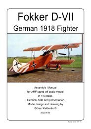
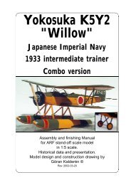
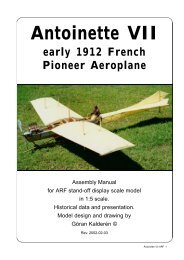
Focke Wulf<br />
FW-44 Stieglitz<br />
1932<br />
Assembly and finishing <strong>Manual</strong><br />
for ARF stand-off scale model<br />
in 1:5 scale.<br />
Historical data and presentation.<br />
Model design and construction drawing by<br />
Göran Kalderén ©<br />
Rev. 2000-05-25
Swedish Airforce aircraft No 670, type FW44J, was built by Focke Wuld Flugzeugbau GmbH<br />
in Germany. These pictures were taken in August 1976 at Malmen by Linköping, Sweden, show all<br />
relevant details. This year the Swedish Airforce celebrated its 50th year anniversary. The aircraft<br />
was transferred from Wing No 3 to wing No 5 shortly thereafter.<br />
Focke Wulf FW 44 ARF 2
Focke Wulf FW44J, here at the F3 wing<br />
airfield, Malmslätt near Linköping, Sweden,<br />
preserved by the Swedish Airforce Museum.<br />
This aircraft is still in good flying condition and<br />
has been flown at air shows during recent years.<br />
This aircraft is one of several survivors in<br />
Sweden. The cockpit photos reveal that only the<br />
rear cockpit has full instrumentation. This was<br />
not common but may be a result of the aircraft<br />
serving as glider tow airplane, until handed over<br />
to the museum.<br />
Focke Wulf FW 44 ARF 3
Specifications:<br />
Type: Focke Wulf Fw 44J:<br />
Function: Sports trainer<br />
Crew: 2<br />
Engine: One Siemens Bramo Sh 14a<br />
Wingspan: 9.01m<br />
Length: 7.29m<br />
Height: 2.83m<br />
Wing area:<br />
20sqm<br />
Focke Wulf FW 44 ARF 4<br />
Weight: Empty:<br />
Loaded weight:<br />
Maximum speed:<br />
Cruising:<br />
Service ceiling:<br />
Maximum range:<br />
525kg<br />
770kg for aerobatics<br />
870kg for training<br />
900kg for touring<br />
115 mph<br />
107 mph<br />
12792 ft<br />
420 miles
Right top: Siemens Bramo Sh-14, 7 cylinder radial<br />
aircooled engine, 150 hp.<br />
Left top: Original lubrication chart for landinggear.<br />
This chart gives a clear view of the landingear<br />
design.<br />
Left center: Original lubrication chart for airframe<br />
controls.<br />
Below: FW44c as trainer in the German Airforce<br />
in 1939 -1945 with grey camouflage paint and<br />
contemporary unit markings.<br />
Focke Wulf FW 44 ARF 5
Focke Wulf FW-44 Stieglitz<br />
When Kurt Tank joined the Focke Wulf<br />
Flugzeugbau GmbH as technichal chief, his first<br />
design to take to the air in 1932 was the Fokke<br />
Wulf FW-44 Stieglitz (Goldfinch). It was designed<br />
to meet the requirements of a number of<br />
German expert aerobatic pilots like Gerd<br />
Achgelis, Emil Kropf and Ernst Udet. It proved<br />
to be an excellent aircraft fully capable of the<br />
aerobatic maneuvres performed by these pilots.<br />
The first prototype was equipped with an 150 hp<br />
Bramo Siemens Sh-14a radial engine.<br />
A large number of Stieglitz were sold and<br />
delivered to countries like Bolivia, Bulgaria, Chile,<br />
China, Finland, Hungary, Sweden, Rumania,<br />
Turkey and Slovakia.<br />
Demand could not be met within the factory<br />
and several aircraft were built under licence in<br />
Sweden, Argentinia, Turkey and Brazil.<br />
Work began on the Fw 44 in 1931 shortly after<br />
the amalgamisation of Focke-Wulf wit Albatros-<br />
Flugzeugwerke and was the first complete aircraft<br />
designed at Focke-Wulf under the guidance<br />
of Kurt Tank. It was designed as a two-seat biplane<br />
for sporting and primary training use. The<br />
Fw 44 was instrumental in establishing Focke-<br />
Wulf Flugzeugbau when substantial orders were<br />
received for the plane.<br />
The plane first flew in late summer 1932 powered<br />
by a seven cylinder air-cooled radial engine,<br />
the Bramo Siemens Sh 14a, but displayed<br />
many faults. Considerable test flying by Kurt<br />
Tank lead to much redesign, The Fw 44<br />
emerged as an aircraft with excellent flight characteristics<br />
and strength.<br />
The Fw 44’s reputation was much enhanced<br />
by its use as an aerobatic display aircraft by the<br />
top german pilots of the day.<br />
The Fw 44C, the main production model,<br />
was a strut and wire braced biplane, the wings<br />
having equal span and slight sweepback, stagger<br />
and dihedral. The lower wings were attached<br />
to the bottom of the fuselage, the upper by struts.<br />
The wings were of wood and fabric. The fuselage<br />
was of welded steel construction covered<br />
by metal panels as far back as the cockpit and<br />
the remainder by fabric.<br />
Our model is based on one of the remaining aircraft,<br />
the Focke Wulf FW44 J, now on display in<br />
the Swedish Airforce Museum in Linköping, Sweden.<br />
Restored FW 44 j flying in California, USA.<br />
Markings from 1937 - 1940 period of the<br />
Swedish Airforce.<br />
Present restored FW 44 c in Germany (note the<br />
tail wheel, necessary for hard surface runways)<br />
and below our model of the A/C to the right.<br />
Focke Wulf FW 44 ARF 6<br />
Proud student pilot in front of his aircraft
German Airforce paint scheme in<br />
the early part of WW2<br />
The Model<br />
We have chosen the scale of 1:5 rendering<br />
a model size that i easy to fly but also<br />
relatively easy to transport. Both the upper and<br />
the lower wing panels can be removed for<br />
transportation which gives very limited<br />
requirement for transportation size. We<br />
recommend a .90 4-stroke or a .75 2-stroke<br />
engine. The 4 stroke engine fits in upright position<br />
and blends very nicely with the dummy engine<br />
cylindres. This aircraft was designed for<br />
aerobatics of the time and can be flown through<br />
advanced manouevres. At the same time it was<br />
a trainer and the low speed behaviour is rather<br />
docile and allows for the pilot to think...<br />
This model has all control surfaces<br />
connected in scale fashion. The ailerons are<br />
actuated via connecting rods to bellcranks in the<br />
lower wings, which i turn are connected with<br />
wires via pulleys to the ailerons in the lower<br />
wings. The upper ailerons are connected with<br />
dual wires from the lower ailerons in scale<br />
fashion. The elevator is actuated via pull-pull<br />
cables from the control column. The rudder in<br />
turn has conventional pull-pull cables to the<br />
rudder bar.<br />
The finished model is painted in 1940<br />
Swedish Airforce livery and further detailing can<br />
be made as per documentation. This model can<br />
also be supplied in various German liveries.<br />
Model specification<br />
Wingspan: 72" (180 cm),<br />
Length: 58.4" (146 cm),<br />
Wing area: 1138 sq inch (80 dm²)<br />
Weight: 11 lbs 5 oz. (5400 g)<br />
Wing Load: 23.5 oz/sq' (70 g/dm²)<br />
Engine: .60-.75 cc (10-12.5cc) 2-<br />
stroke, .80 - .90 4 stroke<br />
Covering and finish<br />
The model is covered and painted from the<br />
factory. If you are going to use a glowplug or<br />
gasoline engine for flying, you must coat the<br />
interior of the engine compartment with a fuel<br />
proof paint.<br />
Installation of engine and radio<br />
We recommend that you don't overpower<br />
this model. It will fly happily with a .60 - .75 standard<br />
2-stroke engine. No side or down thrust is<br />
deemed necessary but can easily be<br />
incorporated at this time. Details on page 8-9.<br />
Assembly of the Focke Wulf FW44<br />
All parts have been assembled at the<br />
factory and only disassembled for transportation.<br />
Rudder and elevator and aileron wires are<br />
factory adjusted but may need some tensioning<br />
adjustment after a while. Aileron bellcranks are<br />
adjustable to the connecting rod.<br />
Assembly of the tail unit<br />
1. Attach horizontal tail to fuselage using<br />
4 pcs 4 mm nylon countersunk screws. Make<br />
sure that stabilizeris flat against fuselage.<br />
2. Insert fin with vertical spar into<br />
fuselage. Attach fin using 2 pcs 4 mm nylon<br />
countersunk screws. Make sure that fin is<br />
perpendicular to stabilizer.<br />
3. Attach the fin supports with a 2mm<br />
screw and nut in the fin and #2 x 1/4" sheet metal<br />
screws in the stabilizer.<br />
4. Attach the stabilizer support struts to<br />
the fuselage using # 2 x 1/4" screws.<br />
5. Attach the rudder with the hinge pins<br />
and connect the rudder wires to the rudder horn<br />
and the elevator wires to the elevator horns.<br />
Check the action of elevator and rudder.<br />
Continued on page 10 ><br />
Focke Wulf FW 44 ARF 7
Cut out in<br />
top panel<br />
Throttle needle<br />
Fuel<br />
filing<br />
tube<br />
Radio switch on<br />
forward cockpit<br />
instrument panel<br />
Landing gear secured<br />
with 3 mm bolts and<br />
lock nuts<br />
Dummy<br />
exhaust tube may be left<br />
for appearance<br />
Throttle<br />
linkage<br />
and fuel<br />
tubings<br />
Header<br />
Installation of engine, tank and radio<br />
We installed an OS .90 4-stroke<br />
surpass engine and used a flexible header<br />
to lead the exhaust under the fuselage in a<br />
near scale fashion. We also used a 12 Oz.<br />
tank.<br />
1. Remove the dummy engine by<br />
loosening the two screws in the front collector<br />
ring and remove the 2 2 mm screws<br />
and nuts that holds the exhaust tube.<br />
2. Drill the holes in the engine mount<br />
and install 4 6-32 blind nuts for the engine<br />
bolts.<br />
3. Cut out for the engine in the top<br />
cover panel. and drill the hole for the header<br />
in the engine mounting board and in the bottom<br />
cover.<br />
Focke Wulf FW 44 ARF 8<br />
Header exit in<br />
line with dummy silencer<br />
One dummy cylinder is<br />
removed
Rudder and elevator servo<br />
in forward tray<br />
Twin coupled aileron servos in<br />
rearward tray<br />
Tank in the upper tray<br />
center, throttle servo<br />
to the right<br />
Header is<br />
routed to<br />
bottom<br />
aluminum<br />
panel and exits<br />
in line with<br />
dummy<br />
exhaust<br />
Receiver and<br />
battery pack<br />
to the left, secured<br />
with<br />
rubber<br />
bands<br />
4. Remove one cylinder<br />
from the top of the dummy engine<br />
and adjust the cutout in the “crankcase”.<br />
Replace the dummy engine<br />
and check for fit. The OS .90 blends<br />
nicely with the dummy. Cut out and<br />
adjust the rear portion of the exhaust<br />
tube and bend the header<br />
tube to suit the outline. Attach the<br />
header tube with a clamp to the<br />
dummy silencer.<br />
5. Install the throttle servo<br />
in the top compartment and connect<br />
to the throttle lever.<br />
6. Install the tank with silicone<br />
tube connections.<br />
7. Install the aileron, rudder<br />
and elevator servos in the respective<br />
servo trays. Not that the two<br />
aileron servos are interconnected.<br />
8. Place the receiver and<br />
the battery pack along the tank. The<br />
switch can be mounted on the from<br />
cockpit instrument panel.<br />
9. Connect the aileron servos<br />
with ball links or clevices to the<br />
aileron push rods.<br />
10. The same applies to the<br />
rudder and elevator servos connection<br />
to the rudder bar and the control<br />
column.<br />
Check for correct throws on the<br />
control surfaces. The elevator and<br />
ailerons should deflect 20°, the rudder<br />
almost 30°.<br />
Focke Wulf FW 44 ARF 9
The wood and metal construction of the model<br />
Built up<br />
dummy<br />
engine<br />
Functional<br />
scale aileron<br />
control<br />
system<br />
Dummy engine is<br />
built from wood and<br />
metal. Aileron control<br />
is by wire per<br />
prototype. Rudder /<br />
elevator control by<br />
wire to control<br />
column and rudder<br />
bar. Spung tailskid in<br />
scale fashion.<br />
Focke Wulf FW 44 ARF 10
Landing gear has scale oleo, rubber<br />
dampened, spring action as the full size<br />
aircraft. Right hand side aluminum<br />
panel removed.<br />
The elevator is actuated with the joy-stick and<br />
the rudder with the rudder bar.<br />
Assembly of wing panels<br />
1. Push the lower wing halves into the holes<br />
in the fuselage.<br />
2. Attach the upper wing using the 4 Allen<br />
6-32 screws supplied (note that the front screws<br />
are longer and the rear screws shorter). Connect<br />
the aileron bellcranks with push rods to the servo<br />
in the fuselage. Install the link wires between the<br />
lower and upper ailerons. Adjust length so that<br />
all ailerons are neutral. Check the movement of<br />
the ailerons. We recommend that you attach the<br />
aileron pushrods in a manner, acheiving<br />
differential throw of the aileron. Attach the flying<br />
wires in place. Attach the landing wires in place.<br />
3. Install the interplane struts. Secure with<br />
2 mm screws and 2 mm lock nuts. Note that the<br />
rear strut is adjustable at the attachment point<br />
in the lower wing. By turning the screw up or<br />
down you can adjust the wing outer section<br />
incidence and the wash out of the upper wing.<br />
Landing gear<br />
Install the landing gear by securing the legs<br />
with 3 mm screws and lock nuts. The centre<br />
point schould be attached to the landing gear<br />
support tripod with a 3 mm screw and lock nut.<br />
Install the wheels on the shaft and secure<br />
with the stoppers. This type of landing gear relies<br />
on the spring action of the rubber in the oleo<br />
mounting in the landing gear. This is a very<br />
efficient shock absorber. If worn out the rubber<br />
can easily be replaced with a fresh, longer one.<br />
Balancing<br />
The center of gravity / balancing point<br />
should be approx. approx. 13 cm (5.2")<br />
measured from the leading edge center of the<br />
upper wing. Placing the C/G up to ½" further<br />
forward makes the airplane steadier but limits<br />
the aerobatic capability. Make adjustments if<br />
necessary to suit your flying taste..<br />
Flying<br />
The prototype was flown with a OS .90<br />
4-stroke FS which provides ample thrust. Let the<br />
engine swing a 16x6 propeller if possible. This<br />
gives better thrust outside the big dummy engine<br />
and reduces sound to a more realistic level.<br />
Flying characteristics are very forgiving<br />
and will fly hapily on half trottle. Set the elevator<br />
at zero angle for the first flight but be prepared<br />
to give down elevator if the model climbs out too<br />
steep. During the initial take off run you have to<br />
compensate for the torque with right rudder but<br />
as the speed builds up the rudder is returned to<br />
neutrual. This model should fly of the ground and<br />
not be pulled.<br />
The landing approach can be rather<br />
steep as per prototype but the flare out needs<br />
almost full up elevator. Get the tail down to<br />
maintain directional stability. Remember this<br />
was the mount of many of the German aerobatic<br />
aces.<br />
Happy landings!<br />
Focke Wulf FW 44 ARF 11
What is in the box:<br />
The ARF kit contains the parts shown in the picture.<br />
All the parts are covered and painted. All the rigging<br />
wires are supplied in the correct lengths and need<br />
only to be clipped to their positions.<br />
16<br />
4<br />
9<br />
7<br />
12<br />
11<br />
14<br />
1<br />
13<br />
15<br />
4<br />
8<br />
5<br />
8<br />
2<br />
6<br />
10<br />
3<br />
1. Fuselage with wing cabane<br />
2. Landing gear with scale function<br />
3. Scale wheels<br />
4. Dummy engine with manifold<br />
5. Scale propeller<br />
6. Tail skid assy.<br />
7. Fin with rudder<br />
8. Stabilizer / elevator<br />
9. Upper wing panels<br />
10. Lower wing panels<br />
11. Interplane struts<br />
12. Aileron connecting wires<br />
13. Landing wires with turnbuckles<br />
14. Flying wires with turnbuckles<br />
15. Cabane cross-support wires<br />
16. Assembly manual with scale documentation<br />
K&W<br />
Model<br />
Airplanes Inc.<br />
Focke Wulf FW 44 ARF 12<br />
P.O.Box 1229, Cebu City Centrl. Postoffice<br />
Cebu City 6000, Philippines<br />
Visiting address:<br />
3343 Gun-Ob, Kinalumsan,<br />
Lapu-Lapu City 6015, PHILIPPINES<br />
Phone +63 32-340 7147, Cellular +63 917-3200 985<br />
Telefax +63 32-340 7131, E-mail: kwmairpl@gsilink.com<br />
Website http://www.gsilink.com/user/kwmairpl