Download PDF Manual - Macca's Vintage Aerodrome
Download PDF Manual - Macca's Vintage Aerodrome
Download PDF Manual - Macca's Vintage Aerodrome

You also want an ePaper? Increase the reach of your titles
YUMPU automatically turns print PDFs into web optimized ePapers that Google loves.
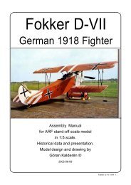
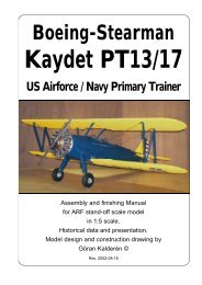
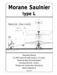
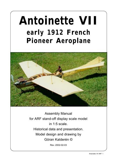
Antoinette VII<br />
early 1912 French<br />
Pioneer Aeroplane<br />
Assembly <strong>Manual</strong><br />
for ARF stand-off display scale model<br />
in 1:5 scale.<br />
Historical data and presentation.<br />
Model design and drawing by<br />
Göran Kalderén ©<br />
Rev. 2002-02-03<br />
Antoinette VII ARF 1
An all most original Antoinette resides in<br />
Muse de f’air et Espace, Le Bourget, Paris.<br />
An original Antoinette VII is on display<br />
in Science Museum in London.<br />
Close up of engine<br />
on British Antoinette VIII<br />
Antoinette VII ARF 2
Details of the AntoinetteVII in the British<br />
Museum of Science in London.<br />
1 - 2. Undercarriage with suspension.<br />
3. Radiator along the fuselage sides.<br />
4. Tailskid, elevator and rudder assemblies.<br />
5. Wing structure and lower wing king posts.<br />
6. Propeller protection front skid<br />
7. AntoinetteVII water cooled V-8 engine.<br />
8. The french Antoinette, left side view.<br />
1<br />
2<br />
3<br />
4<br />
6<br />
5<br />
7<br />
8<br />
Antoinette VII ARF 3
Antoinette VII<br />
The prototype of the Antoinette was designed<br />
by Leon Levavasseur and constructed and built by<br />
Gastanbide and Mengin in 1906. These two gentlemen<br />
had long experience in building marine engines. The<br />
marine influence is clearly noticable in the aircraft<br />
fuselage design. The aircraft were named after the<br />
company director Jules Gastanbide's daughter. There<br />
were eight different designs of which the models from<br />
number IV and up, were good flyers. Allready in 1909<br />
Hubert Latham made an attempt to cross the English<br />
Channel using an Antoinette type IV. In 1911 Mr<br />
Latham made a second unsuccesful attempt to cross<br />
the English Channel this time in an Antoinette VII.<br />
The engine was a fuel injected, liquid cooled<br />
50 hp V-8, with a very low weight/hp output rate. The<br />
radiators for cooling were sidemounted on the fuselage<br />
and of original design. The engine was started with a<br />
handcrank and the propeller shaft output was 1200<br />
rpm. The airfoil used was created to give maximum<br />
penetration and had a high lift factor. The wingarea<br />
was 50 m² and wing and control surfaces were covered<br />
with varnished linen fabric, rubberized and waterproofed.<br />
Horizontal control was conventional with rudder and<br />
elevator. The rudder was actuated via a rudder bar and<br />
the elevator with the starbord control wheel. Lateral<br />
control was obtained by wing-warping using the port<br />
control wheel.<br />
The maximum speed was 55 mph and the<br />
Antionette held many records for speed, duration and<br />
altitude. At one time an Antionette held the world<br />
record for distance. The range was approx. 100 miles.<br />
Our model is in details based on the aircraft<br />
on display in Science Museum in London. This is<br />
Hubert Lathams original aircraft.<br />
There is another aircraft exhibited in Musée<br />
de L’air in Paris. This specimen is not truly original as<br />
the wings and control surfaces have been built after<br />
WW2, but using original construction drawings and<br />
documentation from the period. The engine and<br />
fuselage were used 1909/1910 for research at l’lnstitut<br />
Aerodynamique de Saint-Cyr and was donated to the<br />
museum in 1921.<br />
A third aircraft exists in Krakow in Poland but<br />
is presently not available for viewing or photography.<br />
A replica was built in the US and was aquired<br />
by the Owls Head Transportation Museum in Maine,<br />
USA. This aircraft is still lacking engine and covering<br />
and has a highly modified airfoil.<br />
Note that photographs of the same aircraft on<br />
different occasions show varied constructional details.<br />
At Reims 1912 it was fitted with external ailerons in<br />
lieu of wingwarping.<br />
Antoinette VII replica built for the Owls Head Transportation Museum in Maine, USA.<br />
Hubert Lathams Antoinette at Reims 1909. Note the temporarily added ailerons.<br />
Antoinette VII ARF 4
Artist's rendition of the Reims air contest. The Antoinette<br />
can be seen just to the right of the pylon.<br />
Hubert Latham at the controls of his Antoinette VII. The<br />
elevator was controlled with the starboard wheel. Visible<br />
above is the throttle control.<br />
Above the unhappy ending of the first<br />
attempt to cross the Channel. Latham<br />
is smoking a cigarette while waiting to<br />
be picked up. Below the ending of the<br />
second attempt. This time he had a<br />
narrow escape from drowning.<br />
At Reims, in<br />
August 1909<br />
Latham had<br />
success with<br />
the Antoinette VII<br />
and won the<br />
altitude prize.<br />
Well earned and<br />
some comfort<br />
for earlier<br />
failures.<br />
Antoinette VII ARF 5
Antoinette VII<br />
Specification:<br />
Wingspan: 39 ft 11.7 m<br />
Length: 39 ft 11.7 m<br />
Gross weight 1500 lbs 680 kg<br />
Engine: 50 hp Antoinette<br />
water-cooled V-8.<br />
Antoinette VII ARF 6
The Model<br />
I have chosen the scale 1:5, as it gives a<br />
reasonable big airplane but small enough to handle in a<br />
car.<br />
As you can see from the documentation the<br />
variations of the Antionette VII are numerous and your<br />
choice can be any one of the depicted aircrafts. Also,<br />
the same aircraft has different appearances at different<br />
occasions.<br />
The airplane comes with the fuselage in two<br />
parts with the landing gear attached to the front section<br />
and the tail feathers attached to the rear section. It<br />
remains only to join the two sections and hook up the<br />
control wires from the tail section. The wings are pushed<br />
into the fuselage in holes located on the sides and the<br />
wing supporting wires attached with the kwick links<br />
"turmbuckles. Attach the wing warping wires. It may be<br />
necessary to adjust the tension of the wires.<br />
Specification<br />
Wingspan 234 cm 92.1 inch<br />
Length 234 cm 92.1 inch<br />
Weight 5400 g 11lb 9oz.<br />
Wing surface 200 dm² 3200 Sq inch<br />
Wing load 25g/dm² 9 oz/sq foot<br />
Engine 4-cycle 15 - 20 cc .90 - 1.20 (RCV)<br />
Installation of engine.<br />
A suitable engine for this model is the British<br />
RCV .90 (15 cc 4-cycle) engine. A vertical firewall<br />
adjusted for this engine has been installed and the<br />
dummy engine fits around and adjacent after this<br />
engine. If you feel more comfortable with more power,<br />
Nylon<br />
screws<br />
you may chose the RCV 120 but bearing in mind that<br />
the extra weight has to be compensated.<br />
This type of engine has several advantages on<br />
this type of aircraft. It is slim and follows the profile of<br />
the real aicraft. Access to starting is away from the<br />
propeller and with the reduction of 2:1 on the propeller<br />
shaft it has a torque that allows a 18"x12 propeller to<br />
be used, all in the interest of the scale flying.<br />
1. Remove the dummy propeller shaft. If you have<br />
to relocate the engine mounts, you can do so and the<br />
blind nuts are not secured with glue.<br />
2. Drill the holes from the tank to the carburator,<br />
preassure tap and the filling cap.<br />
3. Install the engine and connect the throttle<br />
servo.<br />
4. Make cut outs in the dummy engine so that<br />
this will fit around and behind your engine. You may<br />
have to remove some part of the dummy crankcase<br />
and the front rows of cylinders. This "surgery" is<br />
executed by removing a little at the time and checking.<br />
When you are satisfied with the fit and openings, screw<br />
the dummy engine onto the engine mounts using 3<br />
mm screws and washers. We have supplied an<br />
installation sketch for you conveniance.<br />
Install a round fuel tank in lieu of the dummy<br />
tank or us a serie of 5 oz tanks in line. The fuel<br />
consumption of the RCV 1.20 engine is approximately<br />
.75 oz. per minute For the RCV 90 the fuel<br />
consumption is lower but we have no details at this<br />
moment.. For a 15 minute flight you would need a 12<br />
oz. tank capacity. Keep the centerline of the tank in<br />
line with the carburator of the engine for best fuel<br />
supply.<br />
Assembly of the two fuselage sections<br />
Locating pin<br />
Tail part<br />
Holes with<br />
4 mm<br />
threads<br />
Front part<br />
Push the locating pins in the tail<br />
part in the 3 holes in the front<br />
part.<br />
Secure with 3 pcs 4 mm diam.<br />
nylon screws from the front end<br />
into the tail section.<br />
Locating pins<br />
This bracket is secured with<br />
3 #1x 1/4" screws from both<br />
sides.<br />
Antoinette VII ARF 7
Removal of seat for access to the<br />
lower part of<br />
the cockpit<br />
Installation of elevator servo<br />
Push the<br />
seat gently<br />
forward and lift up.<br />
The seat slides on the cockpit deck rails.<br />
Radio installation<br />
The radio gear is all installed in the center of<br />
the fuselage under the decking with the two tanks.<br />
The front tray is intended for the receiver, the battery<br />
and the switch. Make compartments on the tray to<br />
suit your equipment. The rear tray is the servo tray,<br />
rudder and elevator servos horizontal and the<br />
wingwarping servo vertical close to the center pylon.<br />
The elevator is actuated via the left steering wheel on<br />
the side of the cockpit. The wingwarping servo is<br />
connected directly to the lower actuating bar on the<br />
landing gear. See details in installation sketches. The<br />
throttle servo is facing forward and has a pushrod to<br />
the throttle on the left hand side of the engine. Make<br />
sure to run the arial away from or not paralell with the<br />
wires! You can let it hang out from below and hook it<br />
to the tail skid.<br />
Installation of rudder servo<br />
Installation of<br />
wing warping<br />
servo<br />
Installation of servos, tank, battery and<br />
receiver.<br />
The wing warping servo is installed in the lower<br />
part of the fuselage.<br />
The trottle servo is installed in the forward tray.<br />
The tank is positioned at the side of this servo.<br />
The elevator servo and rudder servos are<br />
installed rear servo tray.<br />
Battry pack and receiver are positioned under<br />
the front tray tray.<br />
The switch is mounted on the decking between<br />
the two tanks.<br />
1. Attach a ball link head to the rudder bar in the<br />
appropriate hole. You may have to enlarge the holes<br />
to take the screw from the ball link (Dubro #189 set of<br />
2).<br />
2. Install the servos for rudder and elevator and<br />
temporarily connect the servo arms to the ball links.<br />
Deflection for elevator is 20° up and down and for rudder<br />
30° right and left..<br />
3. Install and connect the throttle servo in the<br />
fashion you prefer.<br />
4. Install the tank in the available space in front<br />
of the radio and throttle servos..<br />
5. Install the wingwarping servo in the lower part<br />
of the fuselage. The servo arm attaches to the Kwicklink<br />
allready installed on the wingwarping connection<br />
wires. Deflection should be 1 inch up and down<br />
measured at the wingtip.<br />
6. Fasten the upper servo tray and make the<br />
final connections.<br />
7. Install the radio switch on the decking board.<br />
8. Place the receiver and the battery pack in the<br />
Antoinette VII ARF 8
upper tray, wrapped in foam rubber and secure with<br />
rubber bands.<br />
Assembly of the Antoinette VII<br />
All parts have been assembled at the factory<br />
and only disassembled for packing and transportation.<br />
The fuselage is manufactured in 2 parts, the front<br />
and the rear. The rear part has the tail feathers attached<br />
and the control wires ready to be hooked up with the<br />
corresponding levers in the front fuselage. Rudder and<br />
elevator wires are factory adjusted but may need some<br />
tensioning adjustment after a while.<br />
To access the cockpit flooring and to join the<br />
fuselage parts it is necessary tp temporarily remove<br />
the pilot's seat. See sketch.<br />
1. Join the fuselage halves by pushing the rear<br />
part with the protruding pegs into the front part. Secure<br />
with 3 nylon screws from the front part side and tighten<br />
so that the rear part is firmly attached. Don't over<br />
tighten. This will break the nylon screws. In the event<br />
of a crash, these screwes are intended to brake and<br />
can easliy be replaced. See sketch.<br />
3. Attach the elevator wires and the rudder wires.<br />
Check the action of elevator and rudder. The elevator<br />
is actuated with the right side steering wheel and the<br />
rudder with the rudder bar.<br />
Suggestion for dummy engine installation in<br />
combination with RCV 90. Note the extension of the<br />
propeller shaft, made of aluminum. As the front of the<br />
Antoinette is rather pointed this engine alternativ is<br />
the most suitable if you wish to hide the engine<br />
reasonably well.<br />
4. Push the wing halves into the holes in the<br />
fuselage.<br />
5. Attach the upper wing wires by inserting the<br />
screws in the upper pylon and securing them with the<br />
2 mm nuts. Install the lower (flying) wires and secure<br />
the kwick-links. See sketch.<br />
6. Install the upper wing warping wires and make<br />
sure that they run freely through the pulley. Now attach<br />
the lower wing warping wires and make sure that they<br />
make half a loop on the pulley. Check the wing warping<br />
with the warping actuator.<br />
7. Install the wheels on the shaft and secure<br />
with the stoppers.<br />
Balancing<br />
The center of gravity / balancing point should be approx.<br />
4" = 10 cm from the leading edge of the wing at the<br />
wing root. This aircraft has a very long nose moment<br />
and tends to be nose heavy. Make adjustments by<br />
moving battery and other parts towards the rear. Add<br />
lead in the tail if necessary.<br />
Dummy engine<br />
A dummy of the Antionette 50 hp water cooled V-8 engine<br />
is supplied. Also a scale propeller is attached to the<br />
dummy engine for display.<br />
Flying<br />
Flying characteristics are very special and no<br />
aerobatic manoeuvers suggested. Set the elevator at<br />
zero angle for the first flight but be prepared to give<br />
down elevator if the model climbs out too steep. This<br />
model should fly of the ground and not be pulled by<br />
the propeller. The climb out is shallow and the landing<br />
approach should also be shallow.<br />
Take-off should be done straight into the wind<br />
and the take-off run is relatively short. Make corrections<br />
with elevator and rudder. The wing-warping during takeoff<br />
is slow and not so effective but in flight responsive<br />
enough. Turns should be executed using coordinated<br />
wing-warping and rudder/elevator.<br />
Use gentle handling during approach and<br />
make the landing straight into the wind. On the ground,<br />
taxing, unless very calm weather, should only be<br />
attempted with assistance at the wing tips (as per<br />
prototype).<br />
Happy landings!<br />
Antoinette VII ARF 9
The wooden airframe with the RCV 120<br />
engine temporarily in place.<br />
The tail feathers with<br />
edges of stainless<br />
steel wire.<br />
The landing gear has internal<br />
spring cushioning, wing<br />
warping actuator bar and<br />
wooden alignment guide.<br />
The wire wheels<br />
are uncovered as per<br />
original.<br />
Antoinette VII ARF 10
The Antoinette VII comes complete with elevator actuation from the right side (starboard) wheel<br />
and the wing warping from the left side (port) wheel. For the flying option it will be required to add<br />
wires from the actuator bar on the landing gear to the servo in the fuselage (crossed wires). See<br />
sketches on page 8 for servo installation details<br />
Antoinette VII ARF 11
What is in the box:<br />
The kit contains the parts shown in the<br />
picture below but all covered and painted. All the<br />
rigging wires are supplied in the correct lengths<br />
and need only to be clipped to their positions.<br />
3<br />
1<br />
4<br />
7<br />
1<br />
4<br />
5<br />
2<br />
1. Front of fuselage with wing warping pylon,<br />
dummy engine and landing gear with spoked<br />
wheels.<br />
2. Rear of fuselage with stabilizer/elevator, fin/<br />
rudder and tail skid assy.<br />
3. Left wing panel<br />
4. Right wing panel<br />
5. Scale propeller<br />
6.Wires, turnbuckles and hardware for<br />
assembly (not shown)<br />
7. Assembly manual with scale documentation<br />
Shown above are the uncovered parts<br />
K&W<br />
Model<br />
Airplanes Inc.<br />
P.O.Box 1229, Cebu City Centrl. Postoffice<br />
Cebu City 6000, Philippines<br />
Visiting address:<br />
3343 Gun-Ob, Kinalumsan,<br />
Lapu-Lapu City 6015, PHILIPPINES<br />
Phone +63 32-340 7147, Cellular +63 917-3200 985<br />
Telefax +63 32-340 7131, E-mail: kwmairpl@gsilink.com<br />
Website: www.kwmairpl.com.ph<br />
Antoinette VII ARF 12