Download PDF Manual - Macca's Vintage Aerodrome
Download PDF Manual - Macca's Vintage Aerodrome
Download PDF Manual - Macca's Vintage Aerodrome

Create successful ePaper yourself
Turn your PDF publications into a flip-book with our unique Google optimized e-Paper software.
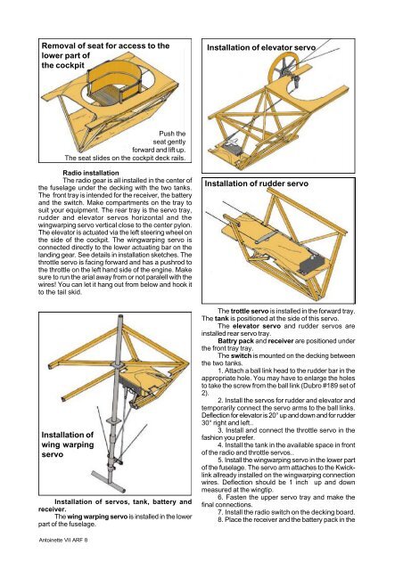
Removal of seat for access to the<br />
lower part of<br />
the cockpit<br />
Installation of elevator servo<br />
Push the<br />
seat gently<br />
forward and lift up.<br />
The seat slides on the cockpit deck rails.<br />
Radio installation<br />
The radio gear is all installed in the center of<br />
the fuselage under the decking with the two tanks.<br />
The front tray is intended for the receiver, the battery<br />
and the switch. Make compartments on the tray to<br />
suit your equipment. The rear tray is the servo tray,<br />
rudder and elevator servos horizontal and the<br />
wingwarping servo vertical close to the center pylon.<br />
The elevator is actuated via the left steering wheel on<br />
the side of the cockpit. The wingwarping servo is<br />
connected directly to the lower actuating bar on the<br />
landing gear. See details in installation sketches. The<br />
throttle servo is facing forward and has a pushrod to<br />
the throttle on the left hand side of the engine. Make<br />
sure to run the arial away from or not paralell with the<br />
wires! You can let it hang out from below and hook it<br />
to the tail skid.<br />
Installation of rudder servo<br />
Installation of<br />
wing warping<br />
servo<br />
Installation of servos, tank, battery and<br />
receiver.<br />
The wing warping servo is installed in the lower<br />
part of the fuselage.<br />
The trottle servo is installed in the forward tray.<br />
The tank is positioned at the side of this servo.<br />
The elevator servo and rudder servos are<br />
installed rear servo tray.<br />
Battry pack and receiver are positioned under<br />
the front tray tray.<br />
The switch is mounted on the decking between<br />
the two tanks.<br />
1. Attach a ball link head to the rudder bar in the<br />
appropriate hole. You may have to enlarge the holes<br />
to take the screw from the ball link (Dubro #189 set of<br />
2).<br />
2. Install the servos for rudder and elevator and<br />
temporarily connect the servo arms to the ball links.<br />
Deflection for elevator is 20° up and down and for rudder<br />
30° right and left..<br />
3. Install and connect the throttle servo in the<br />
fashion you prefer.<br />
4. Install the tank in the available space in front<br />
of the radio and throttle servos..<br />
5. Install the wingwarping servo in the lower part<br />
of the fuselage. The servo arm attaches to the Kwicklink<br />
allready installed on the wingwarping connection<br />
wires. Deflection should be 1 inch up and down<br />
measured at the wingtip.<br />
6. Fasten the upper servo tray and make the<br />
final connections.<br />
7. Install the radio switch on the decking board.<br />
8. Place the receiver and the battery pack in the<br />
Antoinette VII ARF 8