Download PDF Manual - Macca's Vintage Aerodrome
Download PDF Manual - Macca's Vintage Aerodrome
Download PDF Manual - Macca's Vintage Aerodrome

Create successful ePaper yourself
Turn your PDF publications into a flip-book with our unique Google optimized e-Paper software.
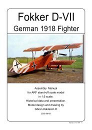
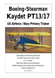
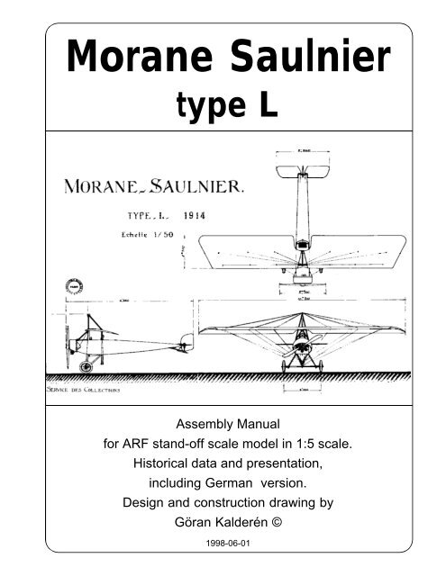
Morane Saulnier<br />
type L<br />
Assembly <strong>Manual</strong><br />
for ARF stand-off scale model in 1:5 scale.<br />
Historical data and presentation,<br />
including German version.<br />
Design and construction drawing by<br />
Göran Kalderén ©<br />
1998-06-01
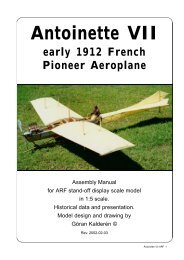
Morane-Saulnier type L<br />
Roland Garros gave this aeroplane fame<br />
in that he flew the first MS type L with a Hotchkiss<br />
machine gun and interrupter gear. He managed<br />
to shoot down one opponent before he himself<br />
was forced to land in enemy territory. The brilliant<br />
french solution of the interrupter gear was of<br />
course copied and improved by the germans and<br />
applied on the better known Fokker E III.<br />
Morane Saulnier type L was designed in<br />
1914, intended for surveillance and artillery observation.<br />
The placing of the wings in a parasol<br />
manner gave both the pilot and the observer an<br />
exellent downward view of the happenings<br />
below. For the benefit of forward and upward<br />
vision a sizeable cutout in the center wing panel<br />
was made.<br />
Also for the flying schools this was an<br />
excellent plane with inherent lateral stability and<br />
The flying school displaying numerous aircrafts.<br />
Morane Saulnier type L -ARF 2<br />
ease of control.<br />
The engine, a french Clerget rotary engine<br />
of 60 hp, gave adequate speed and a generous<br />
wing surface, satisfactory lift. Both the vertical<br />
and horizontal quidance was by all moving<br />
stabilator and rudder and the fuselage gave horizontal<br />
stability.<br />
Lateral control was by wing warping. The<br />
front wing spar is fixed by 6 upper-, landing wires<br />
and 6 lower- flying wires. The rear spar is<br />
controlled by wires running through a pulley in<br />
the topp wire support pylon and a actuator lever<br />
at the lower wire support pylon. The actuator i<br />
coupled to the control collumn by wires. Hence<br />
by moving the control collumn the wires are<br />
activated.<br />
The landing gear is tubular steel and the<br />
wheel shaft is supported with bungee rubbers.<br />
Note that the forward attachment point of the lan-<br />
Musée de l'Air, Paris Musée de l'Air, Paris
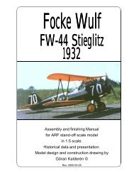
The german version, Pfalz E III, built under licence by Pfalz Flugzeugbau in Steyer, Germany.<br />
Deutsches Museum, München Deutsches Museum, München<br />
Deutsches Museum, München<br />
Morane Saulnier type L -ARF 3
ding gear struts varies from manufacturer to<br />
manufacturer. We have chosen the original<br />
french type for our model.<br />
Pictured is the aeroplane number 274, that<br />
possibly belonged to the same group as shown<br />
in the photo.<br />
The documentation available for the armament<br />
is only, the patent application that was<br />
granted 1914 to Raymond Saulnier. It is no more<br />
than a priciple sketch of the installation of the<br />
Hotchkiss machine gun and the innovative<br />
interrupter gear.<br />
The german company Pfalz Flugzeug Bau<br />
in Steyer, Germany, bought the licence for<br />
manufacturing and the pictures reveal the german<br />
thoroughness, displaying the fuselage construction<br />
in detail and a top view that gives the<br />
wing and tailplane outline.<br />
Caption on the back of the photograph:<br />
"Aircraft readied for land transport. Wings will<br />
be stored along the fuselage".<br />
The german model was photographed in<br />
1916...<br />
If you chose to model the german version,<br />
these pictures give you a fair orientation of the<br />
alterations. It should also be mentioned that the<br />
German crosses underwent noticable changes<br />
during the course of the war. From the original<br />
"Malteese cross" to a more strict angular.<br />
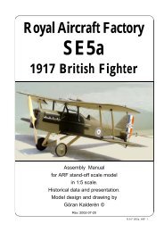
Also in Sweden this model was built under<br />
licence, designated Thulin type D. The swedish<br />
model was later improved with streamlining<br />
of the engine cowl - fuselage and fitted with a 95<br />
hp Thulin A rotary engine, a licence built Le<br />
Rhone engine.<br />
The swedish pioneer Enoch Thulin built<br />
the aircraft under licence, but he also improved<br />
the design, e.g. adding streamlining plywood<br />
panels from the engine cowl to the rear part of<br />
the cockpit.<br />
One aircraft was donated to Finland in<br />
1918 by the swedish count Eric von Rosen and<br />
became the first Finish military aircraft. The finish<br />
plane was endowned with the blue swastika<br />
cross, the crest of the von Rosen family, later to<br />
become the national insignia for Finland.<br />
The first licence built aircraft by Enoch Thulin in Sweden. Note the original design of the fuselage.<br />
Below the same aircraft exhibited in the Stockholm Trade Fair 1915.<br />
Morane Saulnier type L -ARF 4
Prototype specifications:<br />
Manufacturer: Morane-Saulnier Societé de<br />
Constructions Aeronautics, Paris, France.<br />
Length: 20 ft 9 in. Span: 34 ft. Area: 172 sq ft.<br />
Useful load: 550 lbs. Weight loaded: 820 lbs.<br />
Motor 80 hp Gnome rotary. Speed max: 76<br />
mph. Min: 55 mph. Climb rate: 345 ft per min.<br />
Morane Saulnier type L -ARF 5
Color details<br />
Most of the aircrafts had a "natural"<br />
finish. This means unbleached linnen fabric<br />
that was clear doped and then given a<br />
protective varnish finish that resulted in a<br />
yellowish (primrose) tint that bleached to a<br />
greyish-cream shade.<br />
Roundels were carried both above<br />
and below on the wings. Red was the outer<br />
circle, white and blue in the center. The<br />
rudder was divided into three equal fields<br />
with the blue foremost.<br />
Struts and landing gear were painted<br />
black. Wheel disks were black. Tires on<br />
some planes were white. There was also a<br />
black stripe all along the four corners of the<br />
fuselage. The plywood parts had varnished<br />
"natural" color. The access dor on the<br />
forward fuselage sides had black metal<br />
edging.<br />
The "MS" monogram was painted<br />
black on natural aluminum cowlings and<br />
white on black cowlings<br />
Morane Saulnier type L -ARF 6
The model<br />
Specs:Wingspan 220 cm 86,8"<br />
Length 138 cm 54,5"<br />
Wingarea 75,6 dm² 1080 sq"<br />
Weight 3,9 kgs8,6 lb<br />
Wing Loading 52 g / dm² 17 oz/sq'<br />
Engine 10 cc 2-stroke<br />
Although this model is designed with<br />
wing-warping, it can be flown with rudder and<br />
elevator, provided that you employ a wash-out<br />
at the wing tips of approx. 1" (25 mm). This is<br />
done at the moment of rigging.<br />
You have received this model ARF, that<br />
means all the pleasant work is left to be done by<br />
you.<br />
Covering and finish<br />
The model is covered and painted from<br />
the factory. When you have made changes in<br />
the fire wall and adapted the dummy engine to<br />
fit in front of the engine, you will have to cover<br />
the open areas with fuel proof paint.<br />
Installation of engine.<br />
The engine mounts have been installed<br />
in a unusual fashion for several reasons. The<br />
need for adequate cooling. The access to the<br />
glow plug without hole in the cowl and finally to<br />
get the carburator in line with the center of the<br />
tank.<br />
1. Remove the engine mounts and drill and tap<br />
the holes for the engine. Place the engine as<br />
close to the fire wall as possible. If you have to<br />
relocate the engine mounts, you can do so and<br />
the blind nuts are not secured with glue. Should<br />
you desire to install a 4-stroke engine you may<br />
have to make an opening in the firewall for the<br />
carburator and a small "box" so that no fuel<br />
spreads into the fuselage. On the full size plane,<br />
the carburator is licated between the two air<br />
intake tubes!<br />
2. Drill the holes from the tank to the carburator,<br />
preassure nipple and the filling cap.<br />
3. Install the engine and connect the throttle<br />
servo.<br />
4. Make cut outs in the dummy engine so that<br />
this will fit in front of your engine. You may have<br />
to remove 1 complete cylinder to allow for the<br />
cooling air to pass the engine head. This<br />
"surgery" is executed by removing a little at the<br />
time and checking. When you are satisfied with<br />
the fit and openings, screw the dummy engine<br />
onto the engine mounts using 3 mm screws and<br />
washers.<br />
5. Reinstall the engine cowl using 3 #2 sheet<br />
metal screws.<br />
Installation of servos, tank, battery and receiver.<br />
The aileron servo is installed in the servo mount<br />
in the bottom of the fuselage.<br />
The trottle servo and the rudder servo are<br />
installed in the lower servo tray. The tank is<br />
positioned crosswise in front of these servos.<br />
The elevator servo is is installed inverted in<br />
the upper tray.<br />
Battry pack and receiver are positioned in the<br />
upper tray.<br />
The switch is mounted on the dash board.<br />
1. Attach a ball link head to joystick and<br />
rudder bar in the appropriate holes. You may<br />
Morane Saulnier type L -ARF 7
have to enlarge the holes to take the screw from<br />
the ball link (Dubro #189 set of 2).<br />
2. Install the servos for rudder and<br />
elevator and temporarily connect the servo arms<br />
to the ball links. Deflection for elevator is 20° up<br />
and down and for rudder 30° right and left..<br />
3. Install and connect the throttle servo<br />
in the fashion you prefer.<br />
4. Install the tank in the available space in front<br />
of the rudder and throttle servos..<br />
5. Install the aileron servo in the lower<br />
part of the fuselage and connect the two wires<br />
from the warping actuator to the srvo arm. Use<br />
the cerulets provided. Stretch the wire and crimp<br />
the cerulets. Make sure that the servo arm and<br />
the actuator arm are parralell.<br />
6. Fasten the upper servo tray and make<br />
the final connections.<br />
7. Install the radio switch on the<br />
dashboard.<br />
8. Place the receiver and the battery<br />
pack in the upper tray, wrapped in foam rubber<br />
and secure with rubber bands.<br />
Assembly and rigging<br />
There are 30 pcs of rigging wire fittings<br />
consisting of 2 mm Ø threaded bar stock soldered<br />
to wire eylets. On each there is a 2 mm<br />
locking nut.<br />
Landing wires (top of the pylon) 6 pcs<br />
the rest have one kwick-link added.<br />
Flying wires 6 pcs<br />
Warping wires 12 pcs<br />
Elevator wires 4 pcs<br />
Rudder wires 2 pcs<br />
All wires are fixed at one of their locations and<br />
cut to proper length.<br />
Start with the control wires. The drawing<br />
indicates the location. Insert the wire with kwick<br />
link into the hole in the joy stick. The rudder wires<br />
ar fixed to the rudder bar and need only to be<br />
clipped onto the rudder horn. Note that the elevator<br />
wires are crossed in the fuselage.<br />
The wing rigging starts with the landing<br />
wires wich are fixed to the wings. Add the fittings<br />
to the tower threading a nut halfway in. Alternate<br />
left and right starting from the front / inner<br />
positions. Proceed as described earlier. Proceed<br />
with the flying wires, and attaching the fitting to<br />
the locations on the fuselage.<br />
The lower warping wires are fitted to pulleys.<br />
The upper wires are moving freely in the pulley.<br />
The lower wires are turned around and locked<br />
to the pulleys front and aft. Note that the inner<br />
lower warping wires are fixed to the fuselage.<br />
Covering and finish<br />
The model is covered and painted from<br />
the factory. However where you remove material<br />
from the dummy engine, you have to cover<br />
the areas with fuel proof paint.<br />
The original aeroplane was covered with linen<br />
fabric and coated several times with dope. This<br />
gave a translucent, very glossy finish.<br />
The insignia (roundels on the wing upper<br />
and under sides) are painted with enamel. Same<br />
paint is used on the rudder.<br />
Balancing<br />
The center of gravity / balancing point should be<br />
approx. 4" = 10 cm from the leading edge of the<br />
wing, and make adjustments if necessary.<br />
Flying<br />
The photographs on the last page show<br />
flying with one model. Our model has been fitted<br />
The rigging wires<br />
Wing landing wires<br />
Wing warping wires<br />
Wing flying wires<br />
Wing warping wires<br />
Wing warping wires<br />
Morane Saulnier type L -ARF 8
with Super Tigre Blue Head .60 with more than<br />
enough power. It is advisable to fit an engine that<br />
does not protrude to far forward or some<br />
alterations have to be made in the fire wall.<br />
Let the engine swing a 14x4 propeller if<br />
possible. This gives better thrust outside the big<br />
cowl and reduces sound to a more realistic level.<br />
Flying characteristics are very forgiving<br />
but the aerobatic manoeuvers limited. Set the<br />
elevator at zero angle to the wing for the first<br />
flight but be prepared to give down elevator if the<br />
model climbs out too steep. This model should<br />
fly of the ground and not be pulled by the propeller.<br />
Ground handling, taxiing, on hard surface<br />
is difficult in anything but calm weather, because<br />
the model will weather-vane into the wind.<br />
Take-off should be done straight into the<br />
wind and the take-off run is relatively short. Make<br />
corrections with elevator and rudder. The wingwarping<br />
during take-off is slow and not so<br />
effective but in flight responsive enough. Turns<br />
should be executed using both wing-warping and<br />
rudder.<br />
Use gentle handling during approach and<br />
make the landing straight into the wind. On the<br />
ground, taxing, unless very calm weather,<br />
should only be attempted with assistance at the<br />
wing tips (as per prototype). Note that the gliding<br />
ratio with the engine throttled back, is very<br />
steep. Airplanes from this period usually had a<br />
very steep approach for landing.<br />
The model can be used for bomb<br />
dropping and there is ample weight allowance.<br />
The prototype had an over all weight of 3,9 kgs<br />
rendering a wing loading of approx. 17 oz/sq foot<br />
(52 g/dm²), which is a guaranty for slow and<br />
gentle flying.<br />
Happy landings!<br />
The Hotchkiss machinegun was installed<br />
on some aircraft with syncronisation shown<br />
earlier.<br />
Morane Saulnier type L -ARF 9
Servo installation<br />
The sketches below show a typical servo installation.<br />
The pushrods from the servos connect to the joy stick<br />
and the rudder bar with a kwick-link as shown or, with<br />
a ball link which gives a somewhat smother actuation.<br />
Wingwarping set up and wing warping servo installation<br />
Note that the servos are inverted in the tray and that<br />
the pushrods come out under the servo tray. The position<br />
of the tank, receiver and accu are optional and to<br />
the builders discression. The radio switch is<br />
conveniently mounted on the instrument panel<br />
Number 1 servo is the elevator servo, to be connected<br />
with the joy-stick.<br />
Number 2 servo is the rudder servo, to be<br />
connected with the rudder bar.<br />
Number 3 servo is the trhrottle servo to be<br />
connected forward through the firewall<br />
with the carburator/throttle arm.<br />
The wing warping servo is installed in the vertical tray<br />
above the lower pylon. Wires are connected from the<br />
servo arm to the arm of the actuator with the 2 pulleys.<br />
Neutral servo should render horisontal actuator arm.<br />
Wires to the<br />
servo arm<br />
Wing warping wires<br />
Wing warping wires<br />
Actuator arm<br />
The lower wing warping wires are looped half a turn<br />
around the pulley befor being led to the attachment<br />
points in the wing under side. There are two sets of<br />
wires which both are treated the same way. When<br />
there are 2 pulleys, the forward pulley is used for the<br />
shorter wire pair.<br />
Wing warping<br />
lower pulley
Landing gear suspension, bunge rubber installation<br />
The rubberband is laced as illustrated so that<br />
the wheel shaft is tight against the lower part of the<br />
shaft support. The more you stretch the rubber the<br />
harder the spring action will be.<br />
Tail skid bunge rubber installation<br />
The rubberband is attached at the 2 screws as<br />
illustrated. The more you stretch the rubber the harder<br />
the spring action will be.<br />
Rigging of upper pylon and lower wingwarping<br />
wires<br />
The upper landing wires are attached to the pylon in<br />
the sequence illustrated (1-6). Start with the outer<br />
wires and make sure that the wing is parrallel and<br />
perpendicular to the pylon.<br />
The upper wing warping wires are through the pulley<br />
in the upper pylon as illustrated. Start with the outer<br />
wires and make sure that the wing is given approx. 1<br />
inch washout (dihedral at the trailing edge) at the<br />
wingtips. Make sure that the wires run freely in the<br />
pulley.<br />
1.Outer left landing wire<br />
2.Outer right<br />
landing wire<br />
4.Center right<br />
landing wire<br />
3.Center left landing wire<br />
6.Inner right landing wire<br />
5.Inner left landing wire<br />
Outer left wing<br />
warping wire<br />
Inner left wing<br />
warping wire<br />
Outer right wing<br />
warping wire<br />
Inner right<br />
wing warping wire
What is in the box:<br />
The ARF kit contains the parts shown in the<br />
picture. All the rigging wires are supplied in<br />
the correct lengths and need only to be clipped<br />
to their positions.<br />
8<br />
1<br />
5<br />
4<br />
9<br />
7<br />
2<br />
6<br />
3<br />
10<br />
1. Fuselage with wing cabane and wingwarping<br />
pylons<br />
2. Landing gear<br />
3. Scale wheels<br />
4. Engine cowl<br />
5. Dummy engine with mount<br />
6. Scale propeller<br />
7. Tail skid assy.<br />
11<br />
8. Rudder<br />
9. Elevator<br />
10. Left wing panel<br />
11. Right wing panel<br />
12. Wires, turnbuckles and hardware for<br />
assembly (not shown)<br />
13. Assembly manual with scale<br />
documentation (not shown)<br />
K&W<br />
Model<br />
Airplanes Inc.<br />
P.O.Box 1229, Cebu City Centrl. Postoffice<br />
Cebu City 6000, Philippines<br />
Visiting address:<br />
3343 Gun-Ob, Kinalumsan,<br />
Lapu-Lapu City 6015, PHILIPPINES<br />
Phone +63 32-340 7147, Cellular +63 917-3200 985<br />
Telefax +63 32-340 7131, E-mail: kwmairpl@gsilink.com