Download PDF Manual - Macca's Vintage Aerodrome
Download PDF Manual - Macca's Vintage Aerodrome
Download PDF Manual - Macca's Vintage Aerodrome

Create successful ePaper yourself
Turn your PDF publications into a flip-book with our unique Google optimized e-Paper software.
have to enlarge the holes to take the screw from<br />
the ball link (Dubro #189 set of 2).<br />
2. Install the servos for rudder and<br />
elevator and temporarily connect the servo arms<br />
to the ball links. Deflection for elevator is 20° up<br />
and down and for rudder 30° right and left..<br />
3. Install and connect the throttle servo<br />
in the fashion you prefer.<br />
4. Install the tank in the available space in front<br />
of the rudder and throttle servos..<br />
5. Install the aileron servo in the lower<br />
part of the fuselage and connect the two wires<br />
from the warping actuator to the srvo arm. Use<br />
the cerulets provided. Stretch the wire and crimp<br />
the cerulets. Make sure that the servo arm and<br />
the actuator arm are parralell.<br />
6. Fasten the upper servo tray and make<br />
the final connections.<br />
7. Install the radio switch on the<br />
dashboard.<br />
8. Place the receiver and the battery<br />
pack in the upper tray, wrapped in foam rubber<br />
and secure with rubber bands.<br />
Assembly and rigging<br />
There are 30 pcs of rigging wire fittings<br />
consisting of 2 mm Ø threaded bar stock soldered<br />
to wire eylets. On each there is a 2 mm<br />
locking nut.<br />
Landing wires (top of the pylon) 6 pcs<br />
the rest have one kwick-link added.<br />
Flying wires 6 pcs<br />
Warping wires 12 pcs<br />
Elevator wires 4 pcs<br />
Rudder wires 2 pcs<br />
All wires are fixed at one of their locations and<br />
cut to proper length.<br />
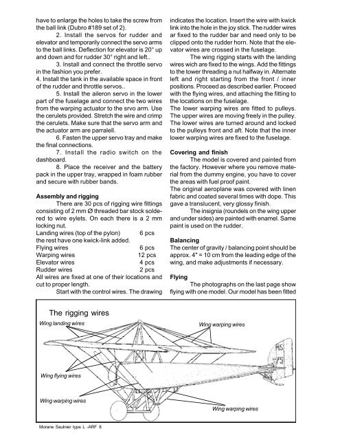
Start with the control wires. The drawing<br />
indicates the location. Insert the wire with kwick<br />
link into the hole in the joy stick. The rudder wires<br />
ar fixed to the rudder bar and need only to be<br />
clipped onto the rudder horn. Note that the elevator<br />
wires are crossed in the fuselage.<br />
The wing rigging starts with the landing<br />
wires wich are fixed to the wings. Add the fittings<br />
to the tower threading a nut halfway in. Alternate<br />
left and right starting from the front / inner<br />
positions. Proceed as described earlier. Proceed<br />
with the flying wires, and attaching the fitting to<br />
the locations on the fuselage.<br />
The lower warping wires are fitted to pulleys.<br />
The upper wires are moving freely in the pulley.<br />
The lower wires are turned around and locked<br />
to the pulleys front and aft. Note that the inner<br />
lower warping wires are fixed to the fuselage.<br />
Covering and finish<br />
The model is covered and painted from<br />
the factory. However where you remove material<br />
from the dummy engine, you have to cover<br />
the areas with fuel proof paint.<br />
The original aeroplane was covered with linen<br />
fabric and coated several times with dope. This<br />
gave a translucent, very glossy finish.<br />
The insignia (roundels on the wing upper<br />
and under sides) are painted with enamel. Same<br />
paint is used on the rudder.<br />
Balancing<br />
The center of gravity / balancing point should be<br />
approx. 4" = 10 cm from the leading edge of the<br />
wing, and make adjustments if necessary.<br />
Flying<br />
The photographs on the last page show<br />
flying with one model. Our model has been fitted<br />
The rigging wires<br />
Wing landing wires<br />
Wing warping wires<br />
Wing flying wires<br />
Wing warping wires<br />
Wing warping wires<br />
Morane Saulnier type L -ARF 8